|
|

Table Of Contents
Connecting Cisco IP VSAT Satellite WAN Network Modules
Prerequisites for the NM-1VSAT-GILAT Network Module
Restrictions for the NM-1VSAT-GILAT Network Module
Information About the NM-1VSAT-GILAT Network Module
General Satellite Network Components
NM-1VSAT-GILAT Network Module Connectors
Outbound and Inbound Directions in a Satellite Communications Network
NM-1VSAT-GILAT Network Module LEDs
How to Install, Connect, or Replace the NM-1VSAT-GILAT Network Module
Installing the NM-1VSAT-GILAT Network Module in the Router Chassis
Connecting the NM-1VSAT-GILAT Network Module to the ODU
Connecting the NM-1VSAT-GILAT Network Module to the External Power Supply
Replacing the NM-1VSAT-GILAT Network Module in the Router Chassis
Connecting Cisco IP VSAT Satellite WAN Network Modules
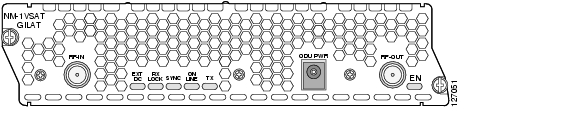
This document provides hardware information about the NM-1VSAT-GILAT network module, which provides Cisco modular access routers with two-way satellite WAN connectivity in Gilat SkyEdge-compatible satellite communications networks. The NM-1VSAT-GILAT network module functions as the indoor unit (IDU) of a very small aperture terminal (VSAT), or earthbound station of a satellite communications network. A "very small" dish antenna is called the outdoor unit (ODU) of a VSAT. As the IDU, the NM-1VSAT-GILAT network module serves as the interface between the ODU and the VSAT LAN. The ODU receives and sends signals to a satellite, and the satellite sends and receives signals from an earthbound central hub, which controls the entire operation of the satellite network. Figure 33-1 shows the NM-1VSAT-GILAT network module faceplate.
Figure 33-1 Cisco IP VSAT Satellite WAN Network Module (NM-1VSAT-GILAT) Faceplate
Contents
•
Prerequisites for the NM-1VSAT-GILAT Network Module
•
•
•
Prerequisites for the NM-1VSAT-GILAT Network Module
•
•
–
–
•
Warning
Note
Restrictions for the NM-1VSAT-GILAT Network Module
•
•
•
–
–
–
•
–
–
–
•
–
–
–
–
•
Note
Information About the NM-1VSAT-GILAT Network Module
Before performing the tasks in this document, you should understand the following concepts:
•
•
•
•
Note
General Satellite Network Components
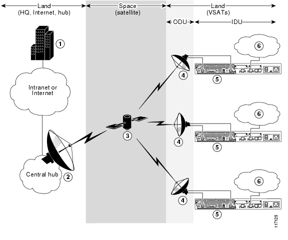
Figure 33-2 shows a satellite communications network that includes NM-1VSAT-GILAT network modules.
Note
Figure 33-2 Satellite Communications Network Using the NM-1VSAT-GILAT Network Module
1 ODU = outdoor unit
2 VSAT = very small aperture terminal
At a high level, the many components of an enterprise satellite communications network can be divided into three categories:
•
•
Satellite
Placed in orbit around the earth, a satellite is a specialized repeater that receives radio-frequency signals from earth stations and retransmits them to other earth stations. The satellite also amplifies the signals and switches the frequencies between the uplink and the downlink carriers. Gilat SkyEdge systems use geostationary satellites with a fixed satellite-to-earth delay of about 250 ms.
Hub
The central hub—sometimes referred to as the "master earth station" but most often simply called the "hub"—contains many components, including:
•
•
•
•
Note
VSATs
A very small aperture terminal (VSAT) is an earth station that can be divided into two areas:
•
–
–
–
•
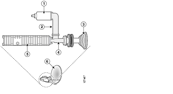
The NM-1VSAT-GILAT network module functions as the IDU of a VSAT and is connected to the ODU through coaxial cables. A power supply is connected to the NM-1VSAT-GILAT network module to provide power over the coaxial cables to the ODU.
Note
Figure 33-3 ODU Components
NM-1VSAT-GILAT Network Module Connectors
Table 33-1 lists the physical connectors that appear on the NM-1VSAT-GILAT network module faceplate.
Outbound and Inbound Directions in a Satellite Communications Network
The outbound direction applies to signals transmitted from the hub to the VSAT. Within a VSAT network, the outbound direction applies to RF communication from the dish antenna (ODU) to the NM-1VSAT-GILAT network module (IDU). From the VSAT perspective, the outbound direction is the receive path. Gilat SkyEdge outbound signals include user data and timing data that are compatible with the Digital Video Broadcasting-Satellite (DVB-S) standard.
The inbound direction applies to signals transmitted from the VSAT to the hub. Within a VSAT network, the inbound direction applies to RF communication from the NM-1VSAT-GILAT network module (IDU) to the dish antenna (ODU). From the VSAT perspective, the inbound direction is the transmit path. Inbound signals include user data and retransmission requests.
NM-1VSAT-GILAT Network Module LEDs
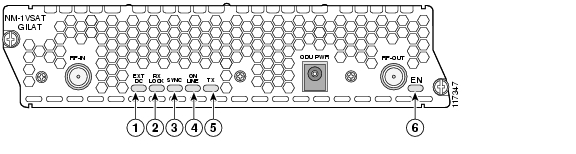
The Cisco IP VSAT satellite WAN network module (NM-1VSAT-GILAT) has six LEDs, shown in Figure 33-4 and described in Table 33-2.
Figure 33-4 NM-1VSAT-GILAT Network Module LEDs
Table 33-2 NM-1VSAT-GILAT Network Module LED Descriptions
Ref.1
EXT DC
Blinking
ODU1 power DC level is correct, and the network module VSAT2 software is running.
Normal indication. No action required.
Steady on
ODU power supply is connected properly, but the network module VSAT software is not running.
Wait until the VSAT software completes the boot process.
Off
ODU power supply is not connected or is outside the specified DC range.
Check ODU power supply connections. See the "Connecting the NM-1VSAT-GILAT Network Module to the External Power Supply" section.
2
RX LOCK
On
Normal indication. No action required.
Off
NM-1VSAT-GILAT network module does not see or recognize the DVB carrier signal from the hub.
The VSAT parameters are configured incorrectly. See the Cisco IP VSAT Satellite WAN Network Module (NM-1VSAT-GILAT) Cisco IOS feature module.
The network module is not properly connected to the LNB.5 Check the RF6 cables or contact your satellite service provider.
The dish antenna is misaligned. Contact your satellite service provider.
There is a hub failure, or the hub is configured incorrectly. Contact your satellite service provider.
3
SYNC
On
NM-1VSAT-GILAT network module is synchronized with the hub timing.
Normal indication. No action required.
Off
NM-1VSAT-GILAT network module is not synchronized with the hub timing.
If the RX LOCK LED is also off, then see the corrective actions for RX LOCK.
If the RX LOCK LED is on while the SYNC LED is off, then the following apply:
•
•
4
ON LINE
On
IP connectivity to the hub is fully established.
Normal indication. No action required.
Off
IP connectivity to the hub was unsuccessful.
If the SYNC LED is also off, then see the corrective actions for SYNC.
If the SYNC LED is on while the ON LINE LED is off, then the following apply:
•
•
•
•
5
TX
Flickering
Inbound8 transmission is in progress.
Normal indication. No action required.
Off
No inbound transmission is in progress.
If you are concerned about the TX LED being off, then try to ping the hub or another destination on the other side of the satellite link. If the TX LED does not flicker during the ping, then the network module is not attempting to send data to the hub.
•
•
•
6
EN
On
The router's Cisco IOS software recognizes the network module.
Normal indication. No action required.
Off
The router's Cisco IOS software does not recognize the network module.
Verify that the network module is properly installed in the router chassis. See the " Installing Cisco Network Modules in Cisco Access Routers" chapter.
1 ODU = outdoor unit.
2 VSAT = very small aperture terminal.
3 DVB = Digital Video Broadcasting.
4 The receive direction at the remote VSAT is called the outbound direction from the hub. See the "Outbound and Inbound Directions in a Satellite Communications Network" section.
5 LNB = low noise block converter.
6 RF = radio frequency.
7 SSPA = solid state block converter and power amplifier.
8 The transmit direction at the remote VSAT is called the inbound direction to the hub. See the "Outbound and Inbound Directions in a Satellite Communications Network" section.
How to Install, Connect, or Replace the NM-1VSAT-GILAT Network Module
This section contains the following procedures, each of which may or may not be required, depending on which tasks your satellite service provider performs for you:
•
•
•
•
Installing the NM-1VSAT-GILAT Network Module in the Router Chassis
To install the NM-1VSAT-GILAT network module in the router chassis, see the " Installing Cisco Network Modules in Cisco Access Routers" chapter of the Cisco Network Modules Hardware Installation Guide.
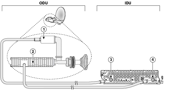
Connecting the NM-1VSAT-GILAT Network Module to the ODU
This section describes how to connect the NM-1VSAT-GILAT network module to the ODU.
Shielded RG-6, RG-11, or both types of RF cables are used to connect the NM-1VSAT-GILAT network module to the ODU. Typically, a satellite service provider installation technician installs the ODU, connects RG-11 cables to the dish antenna, and runs the RG-11 cables to the area near the router. The technician also typically terminates the RG-11 cables and adds short RG-6 cables, which are then connected to the NM-1VSAT-GILAT network module in the router.
Note
Prerequisites
•
•
Steps
To connect the NM-1VSAT-GILAT network module to the ODU, follow these steps:
Step 1
Caution
Step 2
Step 3
Figure 33-5 Connecting the NM-1VSAT-GILAT Network Module to the ODU
What to Do Next
Proceed to the "Connecting the NM-1VSAT-GILAT Network Module to the External Power Supply" section.
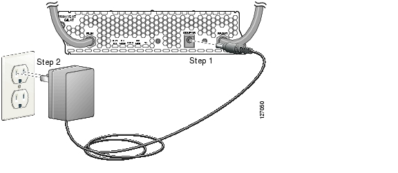
Connecting the NM-1VSAT-GILAT Network Module to the External Power Supply
This section describes how to connect the NM-1VSAT-GILAT network module to the external power supply that comes in the "Sat Kit" provided by a Gilat SkyEdge satellite service provider. The NM-1VSAT-GILAT network module requires additional power to operate the ODU, which includes the dish antenna and its parts, such as the LNB, SSPA, OMT, and feed horn.
Note
Prerequisites
•
•
Restrictions
Only use the power supply provided in the Gilat ODU kit. Use of any other power supply will void the warranties for your NM-1VSAT-GILAT network module and outdoor equipment.
Steps
To connect the NM-1VSAT-GILAT network module to the external power supply, follow these steps:
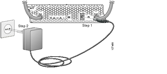
Step 1
Step 2
Figure 33-6 Connecting the NM-1VSAT-GILAT Network Module to the Power Supply (USA)
Figure 33-7 Connecting the NM-1VSAT-GILAT Network Module to the Power Supply (Europe)
What to Do Next
Proceed to the software configuration for your NM-1VSAT-GILAT network module. See the Cisco IP VSAT Satellite WAN Network Module (NM-1VSAT-GILAT) Cisco IOS feature module.
Replacing the NM-1VSAT-GILAT Network Module in the Router Chassis
This section describes how to replace the NM-1VSAT-GILAT network module in your router. Complete one of the following tasks, depending on whether or not your router supports online insertion and removal (OIR):
•
•
Performing Online Insertion and Removal of the NM-1VSAT-GILAT Network Module
The online insertion and removal (OIR) feature enables some Cisco modular access routers to support the replacement of network modules without switching off the router or affecting the operation of other interfaces. Also, routing information is maintained during OIR of network modules.
If your router does not support OIR, do not perform this task to replace your NM-1VSAT-GILAT network module. Instead, go to the "Replacing the NM-1VSAT-GILAT Network Module in a Router" section.
Restrictions
•
•
•
Steps
To perform OIR of the NM-1VSAT-GILAT network module in your router, follow these steps:
Step 1
Step 2
Router> enableRouter# configure terminalRouter(config)# interface satellite slot/0Router(config-if)# shutdownRouter(config-if)# endRouter#Step 3
Caution
Step 4
Step 5
Step 6
Caution
Step 7
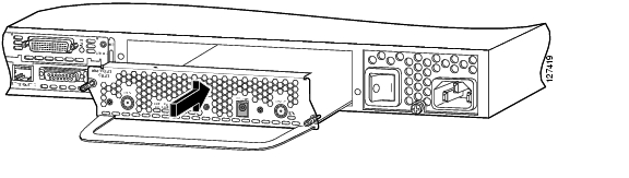
Figure 33-8 Removing a Single-Wide Network Module
Step 8
Figure 33-9 Installing a Single-Wide Network Module
Step 9
Step 10
Caution
Step 11
Step 12
Step 13
Step 14
Step 15
Router> enableRouter# configure terminalRouter(config)# interface satellite slot/0Router(config-if)# no shutdownRouter(config-if)# endRouter#What to Do Next
Configure the initial VSAT parameters for the new NM-1VSAT-GILAT network module. See the
Cisco IP VSAT Satellite WAN Network Module (NM-1VSAT-GILAT) Cisco IOS feature module.
Note
Replacing the NM-1VSAT-GILAT Network Module in a Router
This section describes how to replace the NM-1VSAT-GILAT network module when your router does not support online insertion and removal (OIR). If your router supports OIR, do not perform this task. Instead, go to the "Performing Online Insertion and Removal of the NM-1VSAT-GILAT Network Module" section.
To replace the NM-1VSAT-GILAT network module in your router, follow these steps:
Step 1
Caution
Step 2
Step 3
Step 4
The following warning applies only to routers that use DC power.
Warning
Timesaver
Step 5
Step 6
Caution
Step 7
Figure 33-10 Removing a Single-Wide Network Module
Step 8
Figure 33-11 Installing a Single-Wide Network Module
Step 9
Step 10
Step 11
The following warning applies only to routers that use DC power.
Warning
Caution
Step 12
Step 13
Step 14
Step 15
What to Do Next
Configure the initial VSAT parameters for the new NM-1VSAT-GILAT network module. See the
Cisco IP VSAT Satellite WAN Network Module (NM-1VSAT-GILAT) Cisco IOS feature module.
Note
Related Documents
Regulatory compliance and safety information
Cisco Network Modules and Interface Cards Regulatory Compliance and Safety Information
Cisco IOS software configuration for the NM-1VSAT-GILAT network module
Cisco IP VSAT Satellite WAN Network Module (NM-1VSAT-GILAT)
Platform documentation for the Cisco 2600 series, Cisco 2800 series, Cisco 3700 series, and Cisco 3800 series routers
http://www.cisco.com/univercd/cc/td/doc/product/access/acs_mod/index.htm
Cisco IOS release notes
http://www.cisco.com/univercd/cc/td/doc/product/software/ios123/123relnt/
![]()
![]()
![]()
![]()
![]()
![]()
![]()
![]()
Posted: Fri Dec 14 12:12:53 PST 2007
All contents are Copyright © 1992--2007 Cisco Systems, Inc. All rights reserved.
Important Notices and Privacy Statement.