|
|

Table Of Contents
Connecting Content Engine Network Modules for Caching and Content Delivery
Connecting CE Network Modules to the Network
Online Insertion and Removal with a CE Network Module
Cisco IOS Software Documentation
Cisco Storage Array Documentation
Connecting Content Engine Network Modules for Caching and Content Delivery
This chapter describes how to connect content engine (CE) network modules for caching and content delivery and contains the following sections:
•
Online Insertion and Removal with a CE Network Module
Tip
CE Network Modules
This section provides overview information on CE network modules. The following CE network modules are available on Cisco modular routers:
•
•
•
The 80-GB CE network module can run Application and Content Networking System (ACNS) software or Cisco Wide Area File Services (WAFS) software. The 40-GB CE network module and the CE network module with a SCSI controller can run ACNS software only. For information on configuring ACNS or WAFS, see the documentation listed in the "Related Documents" section.
Caution
Note
Note
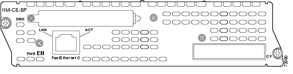
Figure 19-1 Faceplate for the CE Network Module with 40- or 80-GB Disk Expansion Module
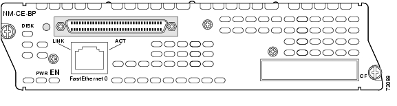
Figure 19-2 Faceplate for the CE Network Module with SCSI Connector Expansion Module
Note
Tip
Connecting CE Network Modules to the Network
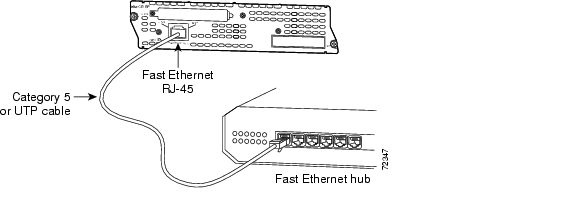
To connect a CE network module to the network, from the RJ-45 port on the CE network module use a straight-through two-pair Category 5 unshielded twisted-pair (UTP) cable to connect to a switch, hub, repeater, server, or other network device. (See Figure 19-3.)
Note
Figure 19-3 Connecting a CE Network Module to a Fast Ethernet Hub
Connecting CE Network Modules with SCSI Controller Expansion Modules to an External Cisco Storage Array
Timesaver
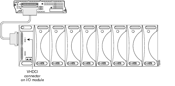
To connect a CE network module with a SCSI controller expansion module to an external storage array, use a 68-pin, low-voltage differential (LVD) SCSI cable. Connect the cable to the SCSI port on the network module to the SCSI port on the external Cisco storage array. (See Figure 19-4.)
Cisco Storage Array 6 is supported on the CE network module with SCSI controller expansion module. (See the Cisco Storage Array 6 Installation and Configuration Guide.)
Tip
Figure 19-4 Connecting a CE Network Module with SCSI Controller Expansion Module to an External Cisco Storage Array
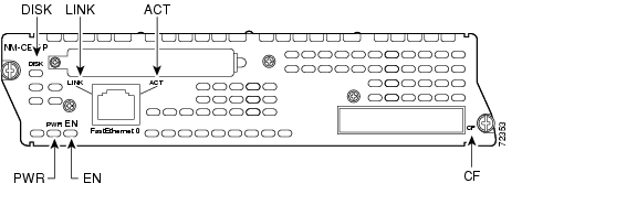
CE Network Module LEDs
All CE network modules have an enable (EN) LED. This LED indicates that the module has passed its self-tests and is available to the router.
CE network modules also display an additional power (PWR) LED and a CompactFlash (CF) LED on the faceplate, and two additional LEDs for the Fast Ethernet port. (See Figure 19-5 and Table 19-1.)
Figure 19-5 CE Network Module LEDs
Online Insertion and Removal with a CE Network Module
Some Cisco modular access routers allow you to replace network modules without switching off the router or affecting the operation of other interfaces. This feature is called online insertion and removal (OIR). OIR of network modules provides uninterrupted operation to network users, maintains routing information, and ensures session preservation. To find out if the router you are working on allows OIR, see the router model's hardware installation guide.
Caution
Caution
For a description of informational and error messages that may appear on the console during this procedure, see the hardware installation guide for your type of router.
To perform online removal of a CE network module and insertion of a replacement, follow these steps with the router in privileged EXEC mode:
Step 1
Router# service-module content-engine slot/unit sessionTrying 10.10.10.1, 2129 ... OpenCE-netmodule con now availablePress RETURN to get started!CE-netmodule> enableCE-netmodule#Step 2
CE-netmodule# copy running-config tftp tftp-server-address filenameStep 3
Step 4
Router# service-module content-engine slot/unit session clear
Step 5
Router# copy tftp running-config tftp-server-addresss filename
Step 6
Router (config)# interface content-engine slot/unitRouter (config-if)# shutdownRouter (config-if)# exitStep 7
Step 8
Step 9
Step 10
Note
Step 11
Step 12
Step 13
Step 14
Router# service-module content-engine slot/unit sessionTrying 10.10.10.1, 2129 ... OpenCE-netmodule con now availablePress RETURN to get started!CE-netmodule> enableCE-netmodule#Step 15
CE-netmodule# copy tftp running-config tftp-server-address filenameStep 16
Step 17
Router# service-module content-engine slot/unit session clear
Related Documents
For information on configuring ACNS, see the documentation at the following URL:
http://www.cisco.com/univercd/cc/td/doc/product/webscale/uce/
For information on configuring WAFS, see the documentation at the following URL:
http://www.cisco.com/en/US/products/ps6469/tsd_products_support_series_home.html
Tip
Hardware Documentation
For information on installing and removing CE network module expansion modules, see the Installing Expansion Modules on Cisco CE Network Modules for Caching and Content Delivery document.
Cisco IOS Software Documentation
For a description of the Cisco IOS features supported on CE network modules, see the Content Engine Network Module for Caching and Content Delivery document.
Content Engine Documentation
For information on the Cisco Content Engine, refer to the documents listed under Cisco Content Engine.
Cisco Storage Array Documentation
For information on installing and configuring the Cisco Storage Array 6, refer to the Cisco Storage Array 6 Installation and Configuration Guide.
![]()
![]()
![]()
![]()
![]()
![]()
![]()
![]()
Posted: Fri Dec 14 11:55:27 PST 2007
All contents are Copyright © 1992--2007 Cisco Systems, Inc. All rights reserved.
Important Notices and Privacy Statement.