|
|

Table Of Contents
Connecting Serial Network Modules
About Data Rates and Distance Limitations
Asynchronous and Synchronous Serial Module Data Rates
Connecting Asynchronous Network Modules to Asynchronous Devices
Asynchronous Network Module Interface Numbering
Cisco 3600 Series and Cisco MWR 1941-DC Router 16- and 32-Port Interface Numbering
Cisco 2600 Series and Cisco MWR 1941-DC Router Serial Interface Numbering
Connecting the 4-Port Serial Module to a Network
4-Port Serial Network Module LEDs
16- and 32-Port Asynchronous Serial Network Modules
Asynchronous Network Module LEDs
4-, 8-, and 16-Port Asynchronous/Synchronous Serial Network Modules
Asynchronous/Synchronous Serial Module LEDs
Connecting Serial Network Modules
This chapter describes how to connect serial network modules for Cisco modular routers and contains the following sections:
•
Connecting Asynchronous Network Modules to Asynchronous Devices
•
•
•
•
Tip
About Serial Connections
Serial connections can be provided by either WAN interface cards or network modules. For more information about WAN interface cards, see the Cisco Interface Cards Hardware Installation Guide. To obtain this publication, see the "Obtaining Documentation" section on page viii.
Before you connect a device to a serial port, you need to know the following:
•
•
•
About DTE and DCE Devices
A device that communicates over a synchronous serial interface is either a DTE or a DCE device. A DCE device provides a clock signal between the device and the router. A DTE device does not provide a clock signal. DTE devices usually connect to DCE devices. The documentation that accompanied the device should tell you whether it is DTE or DCE. (Some devices have a jumper to select DTE or DCE mode.) If you cannot find this information in your documentation, see Table 5-1 to help you determine the proper device type.
Table 5-1 Identifying the Device Type
DTE
Male1
Terminal
PC
DCE
Female2
Modem
CSU/DSU
Multiplexer
1 If pins protrude from the base of the connector, the connector is male.
2 If the connector has holes to accept pins, the connector is female.
Note
About Serial Cables Used with Cisco 2600 Series, Cisco 3600 Series, Cisco 3700 Series, and Cisco MWR 1941-DC Routers
Cisco Systems offers 10 types of serial cables (also called serial adapter cables or transition cables) as listed in Table 5-2.
The documentation for the device you plan to connect to the serial port should indicate which interface is used. You can then order a serial transition cable of the correct type.
Tip
A standard serial cable uses a universal 60-pin plug at the network module or WAN interface card end. The Smart Serial cable uses a 12-in-1 Smart Serial connector designed by Cisco. The network end of each cable provides the physical connectors most commonly used for the interface. For example, the network end of the EIA/TIA-232 serial cable is a DB-25 connector, the most widely used EIA/TIA-232 connector.
All serial interface types except EIA/TIA-530 and EIA/TIA-530A are available in DTE or DCE format: DTE with a plug connector at the network end, and DCE with a receptacle at the network end. V.35 is available in either mode, with either gender at the network end. EIA/TIA-530 and EIA/TIA-530A are available in DTE only.
Serial cables are not provided with the network module. For ordering information, see the "Obtaining Technical Assistance" section on page xi.
Although manufacturing your own serial cables is not recommended (because of the small size of the pins on the DB-60 serial connector), cable pinouts are provided in the online document Cisco Modular Access Router Cable Specifications. For further information, see the "Obtaining Documentation" section on page viii.
About Data Rates and Distance Limitations
All serial signals are subject to distance limits, beyond which the signal degrades significantly or is completely lost. Generally, the slower the data rate, the greater the distance.
Table 5-3 lists recommended maximum speeds and distances for each serial interface type. If you understand and compensate for potential electrical problems, you may get good results at speeds and distances greater than those listed. For instance, the recommended maximum rate for V.35 is 2 Mbps, but 4 Mbps is commonly used.
Balanced drivers allow EIA/TIA-449 signals to travel greater distances than EIA/TIA-232 signals. The recommended distance limits for EIA/TIA-449 shown in Table 5-3 are also valid for V.35, X.21, and EIA/TIA-530. Typically, EIA/TIA-449 and EIA/TIA-530 support 2-Mbps rates, and V.35 can support 4-Mbps rates.
Asynchronous and Synchronous Serial Module Data Rates
The following data-rate limitations apply to the slow-speed serial interfaces found on asynchronous and synchronous serial modules:
•
•
Connecting Asynchronous Network Modules to Asynchronous Devices
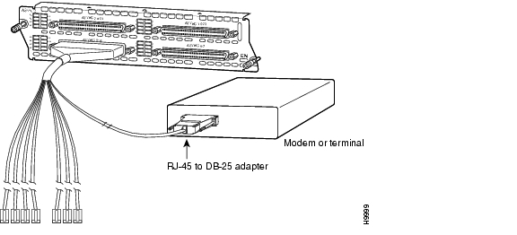
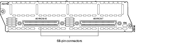
An asynchronous network module provides two or four 68-pin receptacles. Each receptacle connects to asynchronous devices by means of an octal cable that has a 68-pin plug at the module end and eight connectors at the network end, one for each of the eight EIA/TIA-232 serial ports. Depending on the type of cable, the network end consists of either RJ-45 connectors or male DB-25 connectors. RJ-45-to-DB-25 adapters are also available.
Ports are numbered from right to left and from bottom to top, as labeled on the module rear panel. (See the "Asynchronous Network Module Interface Numbering" section.)
Octal Cables
Octal cables are not provided with the network module. For ordering information, see the "Obtaining Technical Assistance" section on page xi.
Use an octal cable, and adapters if necessary, to connect each of the module's 68-pin receptacles to one or more asynchronous modems, terminals, or other devices. (See Figure 5-1.)
Figure 5-1 Connecting an Asynchronous Network Module to an Asynchronous Device
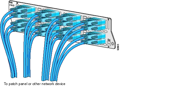
12-in-1 Smart Serial Cables
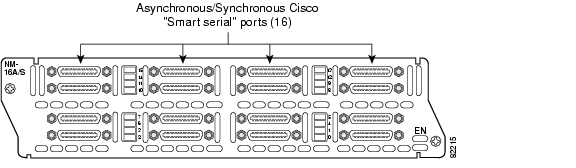
The Cisco NM-16A/S network module uses sixteen 12-in-1 Smart Serial cables. The cables connect the network module to a patch panel or one or more asynchronous modems, terminals, or other devices. (See Figure 5-2.)
Figure 5-2 Connecting the NM-16A/S Network Module
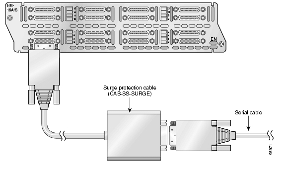
The surge protection cable (CAB-SS-SURGE) is installed between the network module and the 12-in-1 Smart Serial cable. (See Figure 5-3.)
Figure 5-3 Connecting the Cisco Surge Protector Cable (CAB-SS-SURGE) to the NM-16A/S Network Module
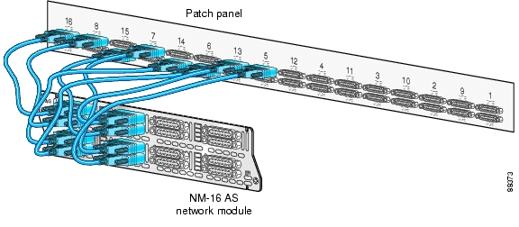
Figure 5-4 shows the 12-in-1 Smart Serial cables going from the Cisco NM-16A/S network module to a patch panel installed above the network module in a standard telco rack. The numbers next to the connectors on the patch panel correspond to the port number (or connector) on the other side of the patch panel.
Figure 5-4 Cabling the Cisco NM-16AS Network Module to a Patch Panel
Asynchronous Network Module Interface Numbering
Certain Cisco IOS configuration commands identify asynchronous ports by an interface number (or a line number, which is the same as the interface number). The interface number of a port on an asynchronous network module is related to the slot number where the module is installed and the unit number of the port in the module.
Cisco 3600 Series and Cisco MWR 1941-DC Router 16- and 32-Port Interface Numbering
Cisco 3600 series and Cisco MWR 1941-DC router slot numbering is explained in the "Network Module Slot Locations and Numbering on Cisco Access Routers" section on page 1-3.
Ports on the 16- and 32-port asynchronous network modules correspond to the outputs of the octal cables that connect the module to the network. These ports are numbered in the same pattern as slot numbers, beginning at 0 at the lower right and continuing from right to left and (in the 32-port module) from bottom to top. In the 16-port module, the right connector provides ports 0 to 7, and the left connector provides ports 8 to 15, as labeled on the module rear panel. In the 32-port module, the connectors in the bottom row provide ports 0 to 7 and 8 to 15, and the connectors in the top row provide ports 16 to 23 and 24 to 31.
The interface number of a port is determined using the following formula:
interface-number = (32 x slot-number) + unit-number + 1
For example, asynchronous port 12 in slot 1 corresponds to interface number
(32 x 1) + 12 + 1 = 45. This is also the line number for the port. Port 12 in slot 1 is always assigned interface number 45, regardless of whether the module in slot 0 is a 16-port asynchronous module, a 32-port asynchronous module, or some other type of module—or even whether there is a network module in slot 0 at all. If you move the module in slot 1 to a different slot, however, its interface numbers change.
Note
Table 5-4 shows the range of interface numbers available for each type of asynchronous network module in each Cisco 3600 series router slot. (Interface 0 is automatically assigned to the console.)
Cisco 2600 Series and Cisco MWR 1941-DC Router Serial Interface Numbering
Interface numbering for Cisco 2600 series and Cisco MWR 1941-DC routers differ from Cisco 3600 series interface numbering in the following ways:
•
•
–
–
Port Interface Numbering
Note
4- and 8-Port
The 4-port and 8-port asynchronous/synchronous network modules, when configured for asynchronous operation under releases earlier than Cisco IOS Release 11.2(7)P, use a different interface numbering algorithm:
interface-number = (16 x slot-number) + unit-number + 1
16- and 32-Port
Table 5-5 shows the numbers available under this numbering scheme. These interface numbers create potential conflicts with the numbers assigned to 16- and 32-port asynchronous modules; that is, it would be possible for a 16- or 32-port asynchronous module in one slot to overlap the interface numbers of a 4- or 8-port asynchronous and synchronous module in another slot.
Table 5-5 4-, 8-, and 16-Port Serial Network Module Interface Numbering
(4-Port Module)
(8-Port Module)
(16-Port Module)0
1-4
1-8
1-16
1
17-20
17-24
17-24
21
33-36
33-40
33-40
3 1
49-52
49-56
49-64
4
N/A
N/A
65-80
5
N/A
N/A
81-96
1 Cisco 3640 and Cisco 3660 routers only.
To prevent this conflict, Cisco IOS Release 11.2(7)P, which is required to operate 16- and 32-port asynchronous network modules, checks when the router boots for the presence of 4- and 8-port asynchronous/synchronous network modules configured as asynchronous. If the software finds any of these network modules, it rewrites the starting configuration in nonvolatile random access memory (NVRAM), if necessary, to adopt the new line numbering scheme for these modules, as shown in Table 5-6.
Table 5-6 New 4- and 8-Port Serial Network Module Interface Numbering
0
1-4
1-8
1
33-36
33-40
21
65-68
65-72
3 1
97-100
97-104
1 Cisco 3640 and Cisco 3660 routers only.
When an automatic configuration update is performed, the following message appears:
Line number convention changed from 16 lines/slot to 32 lines/slot.4-Port Serial Network Module
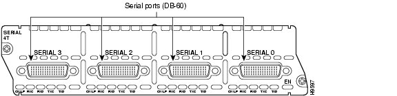
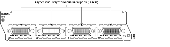
This section provides information about the 4-port serial network module (Cisco product number NM-4T). (See Figure 5-5.) With the appropriate serial transition cable, each port on this module can provide an EIA/TIA-232, EIA/TIA-449, V.35, X.21, EIA/TIA-530 DTE, or nonreturn to zero/nonreturn to zero inverted (NRZ/NRZI) serial interface. The module provides a synchronous data rate of 8 MB per second on port 0, 4 MB per second each on port 0 and port 2, or 2 MB on all four ports simultaneously.
Note
Figure 5-5 4-Port Serial Network Module
Connecting the 4-Port Serial Module to a Network
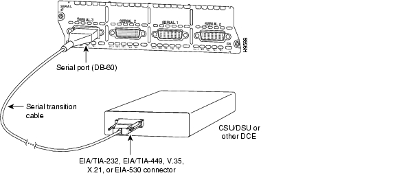
The 4-port serial network module provides four universal, high-density, 60-pin receptacles. The serial cable attached to each receptacle determines the port's electrical interface type and mode, DTE or DCE.
After you install a 4-port serial module, use the appropriate serial cable to connect each of the DB-60 serial ports to a synchronous modem, channel service unit/data service unit (CSU/DSU), or other DCE equipment. (See Figure 5-6.)
Figure 5-6 Connecting a 4-Port Serial Module to a CSU/DSU
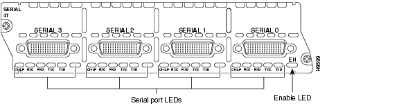
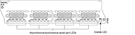
4-Port Serial Network Module LEDs
All network modules have an enable (EN) LED. This LED indicates that the module has passed its self-tests and is available to the router.
Each port on the 4-port serial network module also has the additional LEDs shown in Figure 5-7 and described in Table 5-7.
Figure 5-7 4-Port Serial Network Module LEDs
Table 5-7 4-Port Serial Network Module LEDs
CN/LP
In connect mode when green, in loopback mode when yellow
RXC
Receive clock
RXD
Receive activity
TXC
Transmit clock
TXD
Transmit activity
16- and 32-Port Asynchronous Serial Network Modules
This section provides information about the following network modules:
•
•
When used with corresponding octal cables, these modules provide 16 or 32 EIA/TIA-232 data terminal equipment (DTE) serial interfaces. Speeds up to 134.4 kbps are supported.
Figure 5-8 16-Port Asynchronous Network Module
Figure 5-9 32-Port Asynchronous Network Module
Asynchronous Network Module LEDs
All network modules have an enable (EN) LED. This LED indicates that the module has passed its self-tests and is available to the router.
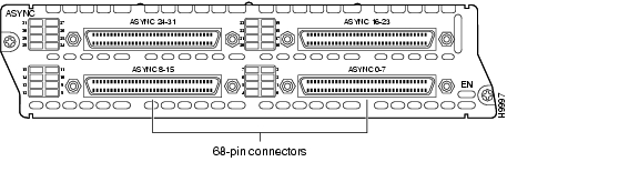
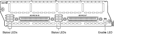
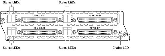
Each port on an asynchronous network module also has a green status LED to indicate that the port is connected to the network. These LEDs are grouped in blocks of eight to the left of each module and are labeled with the port numbers. (See Figure 5-10 and Figure 5-11.)
Figure 5-10 16-Port Asynchronous Network Module LEDs
Figure 5-11 32-Port Asynchronous Network Module LEDs
4-, 8-, and 16-Port Asynchronous/Synchronous Serial Network Modules
This section provides information about the following network modules for Cisco modular routers:
•
•
•
Note
With the appropriate serial transition cable, the ports on these modules can provide an EIA/TIA-232, EIA/TIA-449, V.35, X.21, EIA/TIA-530 DTE, or NRZ/NRZI serial interface. The NM-16 A/S network module can provide an EIA/TIA-530A DTE interface.
Caution
Figure 5-12 4-Port Asynchronous/Synchronous Serial Network Module
Figure 5-13 8-Port Asynchronous/Synchronous Serial Network Module
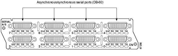
Figure 5-14 16-Port Asynchronous/Synchronous Serial Network Module
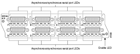
Asynchronous/Synchronous Serial Module LEDs
Figure 5-15 shows LEDs for the 4-port asynchronous/synchronous serial network module. Figure 5-16 shows LEDs for the 8-port asynchronous/synchronous serial network module. Figure 5-17 shows the LEDs for the 16-port asynchronous/synchronous serial network module.
Figure 5-15 4-Port Asynchronous/Synchronous Serial Network Module LEDs
Figure 5-16 8-Port Asynchronous/Synchronous Serial Network Module LEDs
All network modules have an enable (EN) LED. This LED indicates that the module has passed its self-tests and is available to the router.
Each port on an asynchronous/synchronous serial network module also has the additional LEDs shown in Table 5-8.
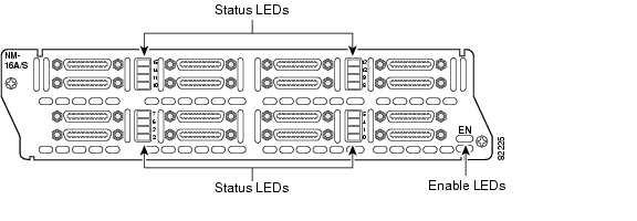
Figure 5-17 16-Port Asynchronous/Synchronous Serial Network Module LEDs
The NM-16 A/S network module has LEDs that indicate the status of the port. When the LED is green, the physical port is in the up state. When the LED is yellow, the port is in loopback mode. (See Table 5-9.)
![]()
![]()
![]()
![]()
![]()
![]()
![]()
![]()
Posted: Fri Dec 14 11:43:17 PST 2007
All contents are Copyright © 1992--2007 Cisco Systems, Inc. All rights reserved.
Important Notices and Privacy Statement.