|
|

Table Of Contents
Connecting T1/E1 IMA Network Modules
Connecting T1/E1 IMA Ports to the Network
IMA Network Module Interface Numbering
Connecting T1/E1 IMA Network Modules
This chapter describes how to connect 4- and 8-port T1 and E1 IMA (inverse multiplexing for ATM) network modules for Cisco modular routers and contains the following sections:
•
Connecting T1/E1 IMA Ports to the Network
•
•
Tip
IMA Network Modules
This section provides information about the following network modules for Cisco modular routers:
•
•
•
•
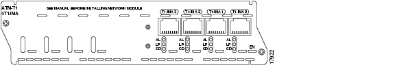
Each port provides 1.544 Mbps/2.048 Mbps connectivity. The IMA aggregation of multiple T1/E1 links increases bandwidth inexpensively to allow WAN uplinks at speeds ranging up to those of a T3/E3 link.
Figure 12-1 4-Channel IMA T1 Network Module
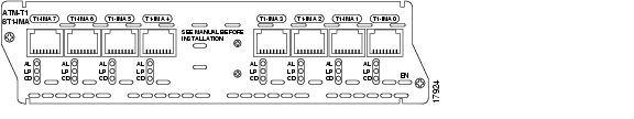
Figure 12-2 8-Channel IMA T1 Network Module
Figure 12-3 4-Channel IMA E1 Network Module
Figure 12-4 8-Channel IMA E1 Network Module
Connecting T1/E1 IMA Ports to the Network
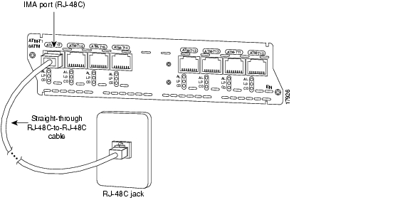
To connect a T1/E1 IMA network module to a network, use a straight-through RJ-48C-to-RJ-48C cable to connect the T1 or E1 port to an RJ-48C wall jack. (See Figure 12-5.)
Figure 12-5 Connecting a T1/E1 IMA Network Module to an RJ-48C Wall Jack
IMA Network Module Interface Numbering
An individual (ungrouped) interface on the IMA network module is numbered by interface type and slot and port number, for example atm 0/2.
An interface that is part of an IMA group loses its individual port number, but adopts the IMA group number, for example atm 0/ima2.
Up to four groups can be created (numbered 0 through 3).
T1/E1 IMA Network Module LEDs
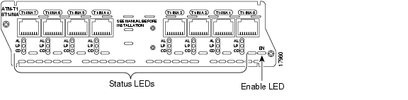
All network modules have an enable (EN) LED. The enable LED indicates that the module has passed its self-tests and is available to the router. T1/E1 IMA network modules have the additional LEDs shown in Figure 12-6 and described in Table 12-1.
Figure 12-6 T1/E1 IMA Network Module LEDs
![]()
![]()
![]()
![]()
![]()
![]()
![]()
![]()
Posted: Fri Dec 14 11:40:17 PST 2007
All contents are Copyright © 1992--2007 Cisco Systems, Inc. All rights reserved.
Important Notices and Privacy Statement.