cc/td/doc/product/access/acs_mod/cis2600/hw_inst/nm_inst
hometocprevnextglossaryfeedbacksearchhelp
PDF

Table Of Contents

Connecting HSSI Network Modules

HSSI Network Modules

Connecting HSSI Modules to the Network

HSSI Network Module LEDs


Connecting HSSI Network Modules


This chapter describes the 1-port High-Speed Serial Interface (HSSI) network module for Cisco 3600 series and Cisco 3700 series routers and contains the following sections:

HSSI Network Modules

Connecting HSSI Modules to the Network

HSSI Network Module LEDs


Tip To determine whether your router supports a specific network module, see Table 1-6 on page 1-16.


HSSI Network Modules

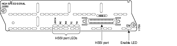
The 1-port High-Speed Serial Interface (HSSI) network module (see Figure 13-1) provides connectivity for fractional DS3 rate links and slower.

Figure 13-1 HSSI Network Module

Connecting HSSI Modules to the Network

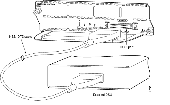
The HSSI module contains a 50-pin receptacle, color-coded blue. You can connect this port to a network in either of two ways:

To an external data service unit (DSU), using a HSSI data terminal equipment (DTE) cable for operation in DTE mode (see Figure 13-2). The HSSI port is configured to operate in this mode by default.

To another router for back-to-back operation, using a HSSI null modem cable. (See  Figure 13-3.) Both routers must be at the same site. Back-to-back operation allows you to verify operation of the HSSI port or link routers directly to build a larger node. Both routers must be configured to use a 51.84-MHz internal clock.

Figure 13-2 Connecting the 1-Port HSSI Module to an External DSU

Figure 13-3 Connecting Two Routers Back to Back

HSSI Network Module LEDs

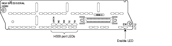
All network modules have an enable (EN) LED. The enable LED indicates that the module has passed its self-tests and is available to the router. The HSSI network module has the additional LEDs shown in Figure 13-4 and described in Table 13-1.

Figure 13-4 HSSI Network Module LEDs

Table 13-1 HSSI Network Module LEDs 

LED
Meaning

LB/C (Loopback/Connect)

Green indicates normal operation. The module is connected to the external DSU, and the signals TA (DTE available) and CA (DCE available) are active.

Yellow indicates that the module is in loopback mode.

If this LED is off, the port is neither connected to the DSU nor in loopback mode.

RC (Receive Clock)

Module has detected a receive clock signal. During normal operation, this signal is received from the external DSU. During loopback, it is generated internally.

RD (Receive Data)

Module has detected a receive clock signal. During normal operation, this signal is received from the external DSU. During loopback, it is generated internally.

TC (Transmit Clock)

Module is transmitting a clock signal to the external DSU. During normal operation, this signal is derived from the DSU's RT signal. During loopback, it is generated internally.

TD (Transmit Data)

Module has been detected by and can send packets to the external DSU.


hometocprevnextglossaryfeedbacksearchhelp

Posted: Fri Dec 14 11:39:46 PST 2007
All contents are Copyright © 1992--2007 Cisco Systems, Inc. All rights reserved.
Important Notices and Privacy Statement.