|
|

Table Of Contents
Connecting ATM Network Modules
Connecting ATM-25 Ports to the Network
Connecting ATM T3 and E3 Ports to the Network
ATM T3 Network Module and ATM E3 Network Module LEDs
OC-3 Network Modules for Cisco 3600 and Cisco 3700 Series Routers
ATM-OC3-POM Network Module for Cisco 3800 Series Routers
Fiber-Optic Transmission Specifications
Connecting ATM Network Modules
This chapter describes how to connect Asynchronous Transfer Mode (ATM) network modules for Cisco modular routers and contains the following sections:
•
ATM T3 and E3 Network Modules
Tip
ATM-25 Network Module
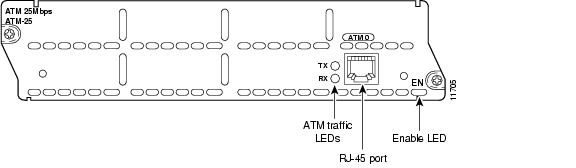
The ATM-25 network module (see Figure 11-1) provides ATM traffic shaping for use with asymmetric digital subscriber line (ADSL) uplink speeds, and protocol support for permanent virtual circuit (PVC) environments. The network module provides full support for multiprotocol encapsulation over ATM Adaptive Layer 5 (RFC 1483), classic IP over ATM encapsulation (RFC 1577), and Point-to-Point Protocol (PPP) over ATM.
Figure 11-1 ATM-25 Network Module
Connecting ATM-25 Ports to the Network
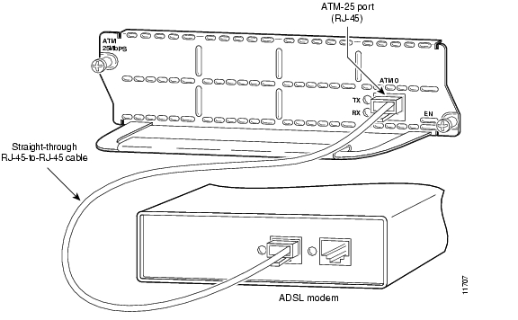
The ATM-25 port is a standard RJ-45 jack, color-coded light green. Use a straight-through modular RJ-45 UTP Category 3, 4, or 5 cable or STP Category 1, 1A, 9, or 9A cable to connect the port to an external ADSL modem. See Figure 11-2.
Figure 11-2 Connecting the ATM-25 Module to an ADSL Modem
ATM-25 Network Module LEDs
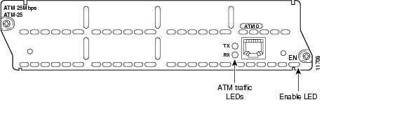
Figure 11-3 shows ATM-25 network module LEDs.
Figure 11-3 ATM-25 Network Module LEDs
All network modules have an enable (EN) LED. The enable LED indicates that the module has passed its self-tests and is available to the router. The ATM-25 network module has the additional LEDs shown in Table 11-1.
Table 11-1 ATM-25 Network Module LEDs
RX
Module is receiving ATM traffic
TX
Module is transmitting ATM traffic
ATM T3 and E3 Network Modules
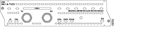
ATM T3 and E3 network modules provide T3 and E3 ATM connectivity for high-bandwidth data applications. There are three versions of these network modules: the ATM T3 Network Module, the ATM E3 Network Module, and the ATM T3/E3 Network Module. See Figure 11-4, Figure 11-5 and Figure 11-6. These network modules offer full support for multiprotocol encapsulation over ATM Adaptive Layer 5 (RFC 1483), classic IP over ATM encapsulation (RFC 1577), Point-to-Point Protocol (PPP) over ATM, and LAN Emulation (LANE). Up to 1024 virtual circuits (VCs) are supported on the ATM T3/E3 network modules.
Figure 11-4 ATM Network Module with T3 Interface
Figure 11-5 ATM Network Module with E3 Interface
Figure 11-6 ATM Network Module with one T3/E3 Interface
Note
•
•
Connecting ATM T3 and E3 Ports to the Network
Use a coaxial cable to connect the module BNC port to a T3 or E3 network.
ATM T3 Network Module and ATM E3 Network Module LEDs
The ATM T3 network module and the ATM E3 network module have the LEDs shown in Table 11-2.
ATM T3/E3 Network Module LEDs
Table 11-3 shows the LEDs for the combined ATM T3/E3 network module.
ATM OC-3 Network Modules
ATM OC-3 network modules provide full 155-Mbps ATM connectivity, including STS-3c and STM-1 framing, for high-bandwidth data applications and voice-data integration applications. Characteristics and installation of these modules are described in the following sections.
•
•
•
OC-3 Network Modules for Cisco 3600 and Cisco 3700 Series Routers
This section describes the following OC-3 (Optical Carrier level 3) network modules for most Cisco 3600 and Cisco 3700 series routers.
Note
The following modules are supported on the Cisco 3600 series routers and the Cisco 3725 router:
•
•
•
The following modules are supported on the Cisco 3745 router:
•
•
•
The following modules are supported on the Cisco 3600 series routers:
•
•
•
Circuit emulation service allows the network module to carry voice traffic, such as telephone calls and faxes, over an ATM network simultaneously with data traffic.
If you are using the ATM OC-3/STM-1 circuit emulation service network module, you need both the network module and a 1- or 2-port T1 or E1 multiflex trunk interface card (VWIC-1MFT-T1, VWIC-1MFT-E1, VWIC-2MFT-T1, VWIC-2MFT-E1, VWIC-2MFT-T1-DI, or VWIC-2MFT-E1-DI) for a voice connection. You can install one multiflex trunk interface card (providing up to two voice ports) in the ATM OC-3/STM-1 circuit emulation service network module. If a multiflex trunk interface card is not installed, the ATM OC-3/STM-1 circuit emulation service network module continues to perform data-routing functions.
To install a multiflex trunk interface card in a network module, see the Cisco Interface Cards Hardware Installation Guide. To obtain this publication, see the "Obtaining Documentation" section on page viii.
Note
Figure 11-7 ATM OC-3 Multimode Fiber Network Module
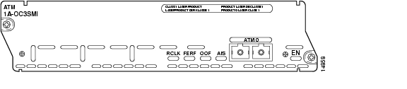
Figure 11-8 ATM OC-3 Single-Mode Intermediate-Reach Fiber Network Module
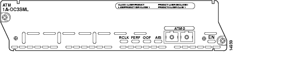
Figure 11-9 ATM OC-3 Single-Mode Long-Reach Fiber Network Module
Figure 11-10 ATM OC-3/STM-1 Circuit Emulation Service Multimode Fiber Network Module
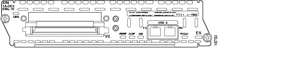
Figure 11-11 ATM OC-3/STM-1 Circuit Emulation Service Single-Mode Intermediate-Reach Fiber Network Module
Figure 11-12 ATM OC-3/STM-1 Circuit Emulation Service Single-Mode Long-Reach Fiber
Network Module
ATM OC-3 Network Module LEDs
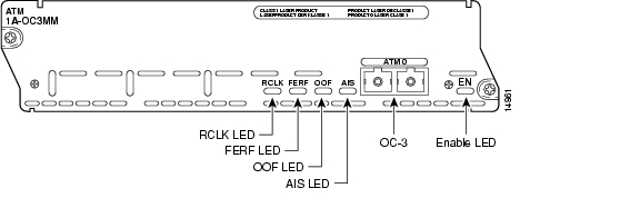
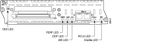
Figure 11-13 and Figure 11-14 show ATM OC-3 network module LEDs. Table 11-4 describes their functions.
Figure 11-13 ATM OC-3 Network Module LEDs
Figure 11-14 ATM OC-3/STM-1 Circuit Emulation Service Network Module LEDs
Hardware Compatibility with Cisco 3620 Routers
Cisco 3620 routers require a minimum PCMCIA controller revision level to recognize ATM OC-3 network modules; otherwise, an error message appears. Cisco 3620 routers installed in the field before April 1999 contain a Revision C PCMCIA controller, which is not compatible with these modules. Starting in April 1999, all Cisco 3620 routers shipped from the factory include Revision E PCMCIA controllers, which are fully compatible with all three ATM OC-3 network modules.
You can identify the version of PCMCIA controller in your Cisco 3620 router by entering the show pci hardware command in privileged EXEC mode, or by examining the part number on the motherboard. Supported versions are shown in Table 11-5.
The output of the show pci hardware command looks similar to this:
Router# show pci hardwareCLPD6729 registers: (0x00) Chip Revision = 0x82 (0x1E) Misc Control 2 = 0x08 (0x1F) Chip Information = 0xE2If you have incompatible hardware, contact the Cisco Systems Technical Assistance Center (TAC) at 800 553-24HR or 408 526-7209, or send e-mail to tac@cisco.com to request a free replacement Cisco 3620 router.
CES Cross-Connection on the Cisco 3660 Router
The Cisco 3660 router can deliver traditional PCM-encoded 64-kbps circuit-based voice over the ATM OC-3 CES network module. To use this functionality, the multiservice interchange card (MIX) must be installed on the Cisco 3660 router. T1/E voice channels on NM-xFE2W and NM-HDV network modules can be transported across the MIX module to ATM OC-3 network modules (NM-1A-OC3XX-1V) over an ATM network. PVC-based (permanent virtual circuit) CES allows service providers to quickly deliver local or long distance voice, while SVC (switched virtual circuit) capabilities ensure that these services are optimized for maximum profitability.
To install the MIX card, see the Installing the Multiservice Interchange Card in Cisco 3660 Routers document. To configure CES, see the OC-3/STM-1 ATM Circuit Emulation Service Network Module document.
Connecting ATM OC-3 Ports to the Network
To connect an ATM OC-3 network module to the network, insert a fiber-optic cable with one duplex SC connector (see Figure 11-15) or two simplex SC connectors (see Figure 11-16) into the ATM interface.
Note
Figure 11-15 Duplex SC Connector
Figure 11-16 Simplex SC Connector
Note
Note
ATM-OC3-POM Network Module for Cisco 3800 Series Routers
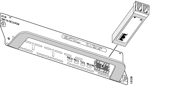
The NM-1A-OC3-POM network module provides a high-performance fiber uplink port for Cisco 3800 series integrated services routers. See Figure 11-17. Supported platforms are:
•
•
Figure 11-17 ATM OC3-POM Network Module
The ATM interface is the small form-factor pluggable (SFP) optical port labeled ATM 0. See Figure 11-17. The optical interface is provided by an SFP module that is inserted into the SFP port. Fiber-optic cables to the network are attached to the SFP module.
The network module has three modes of operation. The mode of operation is determined by the SFP module that is used.
Caution
The modes of operation and usable SFP modules are:
•
–
–
•
–
–
•
–
–
ATM-OC3-POM Network Module LEDs
Table 11-7 describes the functions of the LEDs on the ATM-OC3-POM network module shown in Figure 11-17.
Connecting ATM-OC3-POM Ports to the Network
The following sections describe how to remove and install SFP modules, and how to connect the ports on a module to the network.
Handling an SFP Module
Before handling an SFP module, observe the following guidelines:
•
•
Note
Removing an SFP Module
The following procedure describes removing an SFP module from the network module.
Warning
Caution
To remove an SFP module, perform the following steps:
Step 1
Step 2
Step 3
a.
b.
Note
c.
Step 4
Installing an SFP Module
Use the following procedure to install an SFP module:
Step 1
Step 2
•
•
Step 3
Step 4
Figure 11-18 Installing an SFP Module
Step 5
Step 6
Step 7
Laser Safety Guidelines
ATM OC-3 network modules use a small laser to generate the fiber-optic signal. Keep the transmit port covered whenever a cable is not connected to it.
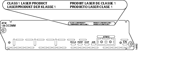
The module faceplate carries a Class 1 laser warning label. See Figure 11-19.
Figure 11-19 Class 1 Laser Warning Label
Warning
Fiber-Optic Transmission Specifications
This section describes Synchronous Optical Network (SONET) specifications for fiber-optic transmissions, defines the power budget, and helps you estimate your power margin for multimode and single-mode transmissions. This section contains the following information:
•
SONET Distance Limitations
The SONET specification for fiber-optic transmission defines two types of fiber, single-mode and multimode. Single-mode fiber allows only one bundle of light rays to propagate through the fiber, whereas multimode fiber allows multiple bundles entering at different angles. Because different bundles (referred to as modes) travel different distances, depending on the entry angle, they arrive at the destination at different times (modal dispersion). Single-mode fiber is capable of higher bandwidth and greater cable run distances than multimode fiber.
Table 11-8 lists typical maximum distances for single-mode and multimode transmissions, as defined by SONET. Use the calculations described in this section to determine the actual maximum for your network. If the distance between two connected stations exceeds this limit, transmission can become unreliable.
Table 11-8 Typical SONET Maximum Fiber-Optic Transmission Distances
MM
1.5 miles (2 km)
SMI
9 miles (15 km)
SML
28 miles (40 km)
Power Budget and Power Margin
Proper operation of an optical data link depends on modulated light reaching the receiver with enough power to be demodulated. The power budget (PB) is the difference between transmitter power (PT) and receiver sensitivity (PR). For instance, if transmitter power is -20 dB and receiver sensitivity is -30 dB, the power budget is 10 dB:
PB = PT - PR
PB = -20 dB - (-30 dB)
PB = 10 dB
The SONET specification requires that the signal meet the worst-case requirements listed in Table 11-9.
Table 11-9 SONET Signal Requirements
Transmitter power
-20 dBm
-15 dBm
-5 dBm
Receiver sensitivity
-30 dBm
-31 dBm
-34 dBm
Power budget
10 dBm
16 dBm
29 dBm
The difference between the power budget and the link loss (LL) is called the power margin (PM). If the power margin is zero or positive, the link should work. If it is negative, the signal may not arrive with enough power to operate the receiver.
Link Loss
Power loss over a fiber-optic link arises from the following causes:
•
•
•
•
•
The power lost over the data link is the sum of all these losses. Table 11-10 gives an estimate of the amount of loss attributable to each cause.
Table 11-10 Link Loss Causes and Amounts
Fiber attenuation
SM: 0.5 dB/km
MM: 1 dB/kmSplice
0.5 dB
Connector
0.5 dB
Modal and chromatic dispersion
Depends on fiber and wavelength1
Higher-order mode losses
0.5 dB
Clock recovery
1 dB
1 Dispersion is usually negligible for single-mode fiber. For multimode fiber, the product of bandwidth and distance should be less than 500 MHz-km.
Estimating the Power Margin
The following example calculates a multimode power margin based on these values:
•
•
•
•
•
•
The power margin is:
PM = PB - LL
= 10 dB - [3 km x (1.0 dB/km) + 4 x (0.5 dB) + 3 x (0.5 dB) + 0.5 dB + 1 dB] = 2 dB
The positive result means this link should have enough power for transmission. The product of bandwidth and distance is 155 MHz x 3 km = 465 MHz-km; this is within the dispersion limit of 500 MHz-km.
Single-Mode Transmission
Single-mode transmission is useful for longer distances, because there is a single transmission path within the fiber and modal dispersion does not occur.
The maximum receive power for SML is -10 dBm, and the maximum transmit power is 0 dBm. The SML receiver can be overloaded when using short lengths of fiber. Overloading the receiver does not damage it, but can cause unreliable operation. To prevent overloading an SML receiver, insert a minimum 10-dB attenuator on the link between any SML transmitter and the receiver.
The SMI receiver cannot be overloaded by the SMI transmitter and does not require a minimum fiber cable length or loss.
The following example of a single-mode power margin assumes these values:
•
•
•
PM = PB - LL
= 16 dB - 8 km x (0.5 dB/km) - 12 x (0.5 dB)
= 6 dB
The positive value means this link should have enough power for transmission.
![]()
![]()
![]()
![]()
![]()
![]()
![]()
![]()
Posted: Fri Dec 14 11:41:23 PST 2007
All contents are Copyright © 1992--2007 Cisco Systems, Inc. All rights reserved.
Important Notices and Privacy Statement.