|
|

Table Of Contents
Connecting Ethernet, Fast Ethernet, and
Token Ring Network Modules1- and 4-Port Ethernet Modules
Ethernet 2-WAN Card Slot Modules
Fast Ethernet 2-WAN Card Slot Modules
Connecting Fast Ethernet Ports
Connecting Ethernet, Fast Ethernet, and
Token Ring Network Modules
This chapter describes how to connect Ethernet, Fast Ethernet, and Token Ring network modules for Cisco access routers. It contains the following sections:
•
Fast Ethernet Network Modules
Tip
Ethernet Network Modules
Ethernet connections are provided on 1- and 4-port Ethernet modules, and on 1-port Ethernet, 2-port Ethernet, and 1-port Ethernet 1-port Token Ring 2-WAN card slot modules.
1- and 4-Port Ethernet Modules
The following network modules provide Ethernet interfaces:
•
•
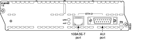
Figure 3-1 1-Port Ethernet Network Module
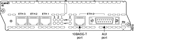
Figure 3-2 4-Port Ethernet Network Module
Ethernet 2-WAN Card Slot Modules
The following 2-slot network modules provide one or two Ethernet interfaces, plus two slots for optional WAN interface cards:
•
•
•
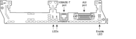
Figure 3-3 1-Ethernet 2-WAN Card Slot Network Module
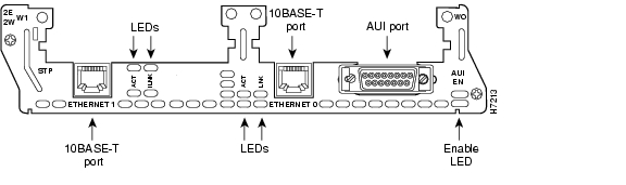
Figure 3-4 2-Ethernet 2-WAN Card Slot Network Module
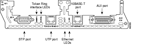
Figure 3-5 1-Ethernet 1-Token Ring 2-WAN Card Slot Network Module
Ethernet Connectors
The 1-port Ethernet network module, the 1-Ethernet 2-slot network module, and the 1-Ethernet 1-Token Ring 2-slot network module each provide a single Ethernet port. This port uses either the attachment unit interface (AUI) DB-15 connector on the right side of the module or the 10BASE-T (RJ-45) connector next to it. Only one of these connectors can be active at a time. The active port is identified in software by port type (Ethernet), slot number on the module, and port number 0.
All modules detect the type of network connection automatically, and you do not need to choose the media type in software. If cables are plugged into both ports, the 10BASE-T connection is chosen.
The 4-port Ethernet network module has ports for four Ethernet connections (0, 1, 2, and 3). Port 0 offers a choice of an AUI or 10BASE-T interface. Ethernet ports 1, 2, and 3 use 10BASE-T connectors only. These ports do not provide an AUI connector.
The 2-Ethernet 2-slot network module has ports for two Ethernet connections. Port 0 offers a choice of AUI or 10BASE-T. Port 1 uses 10BASE-T only.
Connecting Ethernet Ports
If an Ethernet port offers both an AUI connector and a 10BASE-T connector, you can use either connector, but not both at the same time.
AUI Connections
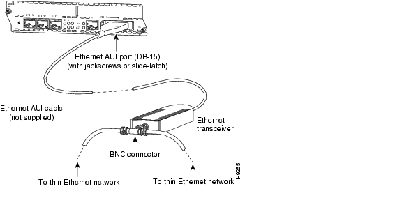
Use an Ethernet AUI cable to connect an AUI port to an Ethernet transceiver. These ports are color-coded yellow. The female end of the AUI cable mates with the slide-latch connector of the transceiver cable. Figure 3-6 shows a thin Ethernet transceiver as an example, but you can use any type of Ethernet transceiver.
If the transceiver cable has thumbscrew connectors, you can connect it directly to the AUI port by replacing the AUI port slide latch with a jackscrew (provided in a separate bag).
Figure 3-6 Connecting an Ethernet AUI Port to a Transceiver
10BASE-T Connections
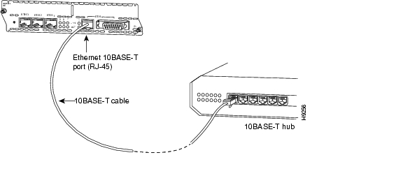
Use an Ethernet 10BASE-T cable to connect a 10BASE-T port to a hub or other network device. These ports are color-coded yellow. Figure 3-7 shows the 10BASE-T port on an Ethernet network module connected to a hub.
Figure 3-7 Connecting an Ethernet 10BASE-T Port to a Hub
Ethernet LEDs
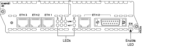
This section describes Ethernet module LEDs. Figure 3-8 shows 4-port Ethernet network module LEDs as an example.
All network modules have an enable (EN) LED. This LED indicates that the module has passed its self-tests and is available to the router.
Each Ethernet port has two LEDs. The activity (ACT) LED indicates that the router is sending or receiving Ethernet transmissions. The link (LINK) LED indicates that the Ethernet port is receiving the link integrity signal from the hub (10BASE-T only).
Figure 3-8 Ethernet Network Module LEDs (Typical)
Fast Ethernet Network Modules
Fast Ethernet connections are provided on 1-port Fast Ethernet modules, and on 1-port Fast Ethernet, 2-port Fast Ethernet, and 1-port Fast Ethernet 1-port Token Ring 2-WAN card slot modules.
Note
1-Port Fast Ethernet Modules
The following network modules provide Fast Ethernet interfaces:
•
•
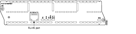
Figure 3-9 1-Port Fast Ethernet Network Module (TX Connector)
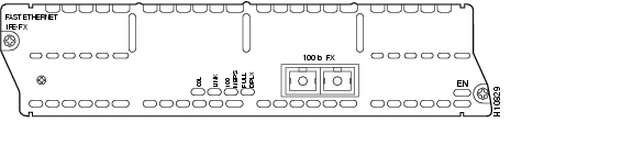
Figure 3-10 1-Port Fast Ethernet Network Module (FX Connector)
Fast Ethernet 2-WAN Card Slot Modules
The following 2-slot network modules provide one or two 100BASE-T Fast Ethernet interfaces, plus two slots for optional WAN interface cards:
•
•
•
Caution
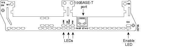
Figure 3-11 1-Fast Ethernet 2-WAN Card Slot Network Module
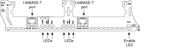
Figure 3-12 2-Fast Ethernet 2-WAN Card Slot Network Module
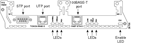
Figure 3-13 1-Fast Ethernet 1-Token Ring 2-WAN Card Slot Network Module
Connecting Fast Ethernet Ports
Use the following sections for 100BASE-T or 100BASE-FX connections.
100BASE-T Connections
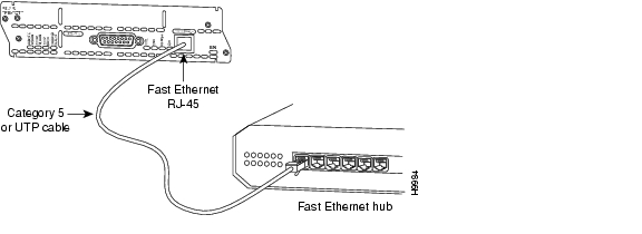
Use a two-pair Category 5 or unshielded twisted-pair (UTP) straight-through RJ-45 cable to connect a Fast Ethernet RJ-45 port to a switch, hub, repeater, server, or other network device. Figure 3-14 shows an RJ-45 port connected to a hub.
Note
Caution
Figure 3-14 Connecting a Fast Ethernet RJ-45 Port to a Hub
100BASE-FX Connections
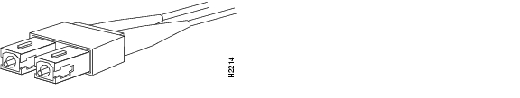
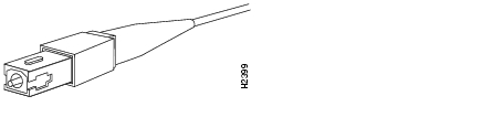
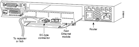
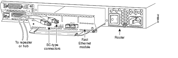
Attach a multimode fiber-optic cable with SC-type connectors directly to the port on the Fast Ethernet network module (remove the protective plug from the port if it is present). Use either one duplex SC connector (see Figure 3-15 and Figure 3-17) or two simplex SC connectors (see Figure 3-16 and Figure 3-18). Attach the other end of the cable to a repeater, hub, or wall outlet. Be sure to observe the correct relationship between the receive (RX) and transmit (TX) ports on the network module and the cable.
Note
Caution
Figure 3-15 Duplex SC Connector
Figure 3-16 Simplex SC Connector
Figure 3-17 Connecting a Fast Ethernet FX Port to a Repeater or Hub (Duplex Connector)
Figure 3-18 Connecting a Fast Ethernet FX Port to a Repeater or Hub (Simplex Connectors)
Fast Ethernet LEDs
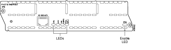
This section describes Fast Ethernet module LEDs. Figure 3-19 shows 1-port Fast Ethernet network module LEDs as an example.
Figure 3-19 1-Port Fast Ethernet Network Module LEDs
All network modules have an enable (EN) LED. The enable LED indicates that the module has passed its self-tests and is available to the router.
Fast Ethernet network modules have the additional LEDs shown in Table 3-1.
Token Ring Network Modules
The following network modules provide Token Ring interfaces:
•
•
Figure 3-20 1-Ethernet 1-Token Ring 2-WAN Card Slot Network Module
Figure 3-21 1-Fast Ethernet 1-Token Ring 2-WAN Card Slot Network Module
Connecting Token Ring Ports
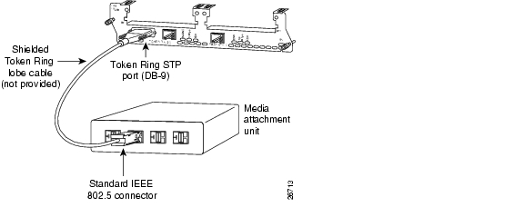
The 1-Ethernet 1-Token Ring 2-WAN card slot network module and the 1-Fast Ethernet 1-Token Ring 2-WAN card slot network module each have one DB-9 connector for an STP Token Ring connection and one RJ-45 connector for a UTP Token Ring connection. Only one connector can be active at a time.
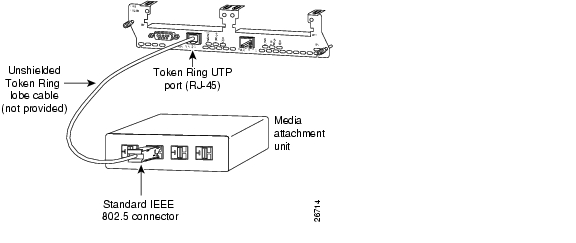
To connect the module to a Token Ring network, attach one end of a shielded Token Ring lobe cable to the DB-9 connector on the network module (see Figure 3-22), or attach one end of an unshielded Token Ring lobe cable to the UTP connector on the network module (see Figure 3-23). Attach the other end of the cable to the Token Ring media attachment unit (MAU). The network module automatically detects which connector is in use.
Figure 3-22 Connecting a Token Ring STP Port (DB-9) to a MAU
Figure 3-23 Connecting a Token Ring UTP Port (RJ-45) to an MAU
Token Ring LEDs
All network modules have an enable (EN) LED. The enable LED indicates that the module has passed its self-tests and is available to the router.
The 1-Ethernet 1-Token Ring 2-WAN card slot network module and the 1-Fast Ethernet 1-Token Ring 2-WAN card slot network module both have the following Token Ring LEDs:
•
•
The 1-Fast Ethernet 1-Token Ring 2-slot network module also has the FDX LED, which indicates full-duplex mode.
Timesaver
![]()
![]()
![]()
![]()
![]()
![]()
![]()
![]()
Posted: Fri Dec 14 11:44:37 PST 2007
All contents are Copyright © 1992--2007 Cisco Systems, Inc. All rights reserved.
Important Notices and Privacy Statement.