|
|

Table Of Contents
Connecting Analog Modem Network Modules
8- and 16-Port Analog Modem Network Modules
8- and 16-Port Analog Modem Network Modules, Version 2
Connecting the Modules to the Telephone Network
Analog Modem Network Module LEDs
Connecting Analog Modem Network Modules
This chapter describes 8- and 16-port analog modem network modules for Cisco modular routers. It contains the following sections:
•
8- and 16-Port Analog Modem Network Modules
•
•
•
Tip
8- and 16-Port Analog Modem Network Modules
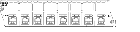
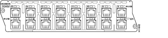
The following analog modem network modules originate or terminate analog telephone transmissions through RJ-11 modular jacks:
•
•
Figure 10-1 8-Port Analog Modem Network Module
Figure 10-2 16-Port Analog Modem Network Module
The following warning applies in Australia:
Warning
The following warning applies in New Zealand:
Warning
Network Protocols Supported
The analog modems described in this chapter support the following protocols:
•
•
•
•
•
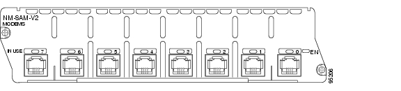
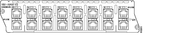
8- and 16-Port Analog Modem Network Modules, Version 2
The following analog modem network modules originate or terminate analog telephone transmissions through RJ-11 modular jacks:
•
•
Caution
Figure 10-3 8-Port Analog Modem Network Module (NM-8AM-V2)
Figure 10-4 16-Port Analog Modem Network Module (NM-16AM-V2)
The following warning applies in Australia:
Warning
The following warning applies in New Zealand:
Warning
Network Protocols Supported
The analog modems described in this chapter support these protocols:
•
–
–
–
–
–
–
–
–
–
–
–
–
–
•
–
–
–
–
–
–
•
–
–
–
–
–
Interface Numbering
Cisco IOS software identifies each modem uniquely by its slot number and port number.
Some Cisco IOS configuration commands identify asynchronous ports by an interface number (or a line number, which is the same as the interface number). The interface number of a port on an 8- or 16-port analog modem network module is related to the slot number where the module is installed and the number of the port in the module.
Ports in the 8- and 16-port analog modem network modules are numbered in the same pattern as slot numbers, beginning at 0 at the lower right and continuing from right to left and (in the 16-port module) from bottom to top.
The interface number of a port is determined in the following way:
interface-number = (32 x slot-number) + port-number + 1
For example, modem port 12 in slot 1 corresponds to interface number (32 x 1) + 12 + 1 = 45. This is also the line number for the port. Port 12 in slot 1 is always assigned interface number 45, regardless of whether the module in slot 0 is an 8-port analog modem network module, a 16-port analog modem module, or some other kind of module entirely, or even whether there is a network module in slot 0 at all. If you move the module from slot 1 to a different slot, however, its interface numbers change.
Table 10-1 shows the range of interface numbers available for each type of analog modem network module in each router slot. (Interface 0 is automatically assigned to the console.)
Connecting the Modules to the Telephone Network
Each analog modem network module provides 8 or 16 RJ-11 jacks for standard modular cables. These ports are color-coded pink. Cables are not provided with the network module.
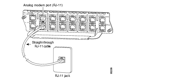
To establish an analog connection, use a straight-through RJ-11 modular cable to connect the jack to a wall telephone outlet. (See Figure 10-5.)
Figure 10-5 Connecting an Analog Modem Network Module
Analog Modem Network Module LEDs
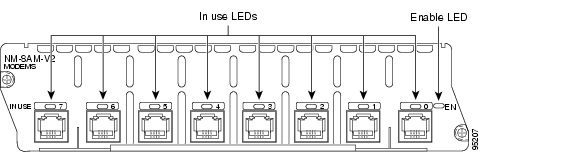
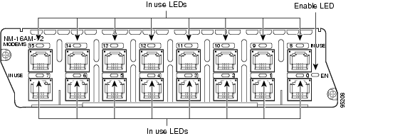
All network modules have an enable (EN) LED. This LED indicates that the module has passed its self-tests and is available.
Each modem in the module has an in use (IN USE) LED that lights when the modem is off-hook. (See Figure 10-6 and Figure 10-7.)
Figure 10-6 8-Port Analog Modem Network Module LEDs
Figure 10-7 16-Port Analog Modem Network Module LEDs
![]()
![]()
![]()
![]()
![]()
![]()
![]()
![]()
Posted: Fri Dec 14 11:38:18 PST 2007
All contents are Copyright © 1992--2007 Cisco Systems, Inc. All rights reserved.
Important Notices and Privacy Statement.