cc/td/doc/product/access/acs_mod/cis2600/hw_inst/nm_inst
hometocprevnextglossaryfeedbacksearchhelp
PDF

Table Of Contents

Connecting Cisco EtherSwitch Service Modules

Cisco EtherSwitch Services Modules

Cisco EtherSwitch Service Module Overview

Cisco EtherSwitch Service Module Ports

Cisco EtherSwitch Service Module LEDs

Power Considerations

Power Considerations for the Router

Power Considerations for the Service Module

Powering Considerations for a Switch Stack

Connecting to the EtherSwitch Service Module Ports

Stacking the Cisco EtherSwitch Service Modules

Planning the Stack

Stack Cabling Considerations

Connecting to the Cisco StackWise Ports


Connecting Cisco EtherSwitch Service Modules


This chapter describes how to connect Cisco EtherSwitch service modules. It contains the following sections:

Cisco EtherSwitch Services Modules

Power Considerations

Connecting to the EtherSwitch Service Module Ports

Stacking the Cisco EtherSwitch Service Modules


Note This document describes the Cisco EtherSwitch service modules only. For information about other Cisco Ethernet switch network modules, see the "Connecting Ethernet Switch Network Modules to a Network" section at the following URL:

http://www.cisco.com/en/US/products/hw/modules/ps2797/products_module_installation_guide_chapter09186a00800b168c.html


Tip To determine whether your router supports a specific network module, see Table 1-6 on page 1-16.


Cisco EtherSwitch Services Modules

Cisco EtherSwitch service modules are complete switching platforms and can be stacked with other Cisco switches to form a switching stack integrated with the router and capable of supporting the following features:

Dynamic addition and removal of individual Cisco EtherSwitch service modules from the switching stack

Integrated management through all management interfaces (command-line interface [CLI], Simple Network Management Protocol [SNMP], and HTTP)

Features such as UplinkFast, EtherChannel, and equal-cost routing across the switching stack that provide redundancy and reduce network disruption from individual component failure

For information about these and other Cisco EtherSwitch service module features, see the Cisco EtherSwitch Service Modules Feature Guide at the following URL:

http://www.cisco.com/en/US/products/hw/modules/ps2797/products_feature_guide09186a0080415bae.html


Note For release note information about Cisco Ethernet switch network modules, see the Release Notes for the EtherSwitch Service Modules, Cisco IOS Release 12.2(25)SEC at the following URL:

http://www.cisco.com/univercd/cc/td/doc/product/lan/cat3750/12225sec/index.htm


This section describes the Cisco EtherSwitch service modules. It contains the following sections:

Cisco EtherSwitch Service Module Overview

Cisco EtherSwitch Service Module Ports

Cisco EtherSwitch Service Module LEDs

Cisco EtherSwitch Service Module Overview

The Cisco EtherSwitch service modules are stackable modules to which you can connect Cisco IP telephones, Cisco wireless access point workstations, and other network devices such as servers, routers, switches, and other network switch modules.

The following modules are available with this release of the hardware:

NME-16ES-1G—16 10/100 Ethernet ports, 1 10/100/1000 Ethernet port, no StackWise connector ports, single-wide, no Power over Ethernet (PoE) support (see Figure 18-1)


Caution To comply with the Telcordia GR-1089 NEBS standard for electromagnetic compatibility and safety, connect the 16-port EtherSwitch service module (NME-16ES-1G) only to intra-building or non-exposed wiring or cabling. The intrabuilding cable must be shielded and the shield must be grounded at both ends.

NME-16ES-1G-P—16 10/100 Ethernet ports, 1 10/100/1000 Ethernet port, no StackWise connector ports, single-wide, with PoE support (see Figure 18-1)


Caution To comply with the Telcordia GR-1089 NEBS standard for electromagnetic compatibility and safety, connect the 16-port EtherSwitch service module with PoE (NME-16ES-1G-P) only to intra-building or non-exposed wiring or cabling. The intrabuilding cable must be shielded and the shield must be grounded at both ends.

NME-X-23ES-1G—23 10/100 Ethernet ports, 1 10/100/1000 Ethernet port, no StackWise connector ports, extended single-wide, no PoE support (see Figure 18-2)


Caution To comply with the Telcordia GR-1089 NEBS standard for electromagnetic compatibility and safety, connect the 23-port EtherSwitch service module (NME-X-23ES-1G) only to intra-building or non-exposed wiring or cabling. The intrabuilding cable must be shielded and the shield must be grounded at both ends.

NME-X-23ES-1G-P—23 10/100 Ethernet ports, 1 10/100/1000 Ethernet port, no StackWise connector ports, extended single-wide, with PoE support (see Figure 18-2)


Caution To comply with the Telcordia GR-1089 NEBS standard for electromagnetic compatibility and safety, connect the 23-port EtherSwitch service module with PoE (NME-X-23ES-1G-P) only to intra-building or non-exposed wiring or cabling. The intrabuilding cable must be shielded and the shield must be grounded at both ends.

NME-XD-24ES-1S-P—24 10/100 Ethernet ports, 1 small form-factor pluggable (SFP) port, 2 StackWise connector ports, extended double-wide, with PoE support (see Figure 18-3)


Warning To comply with the Telcordia GR-1089 NEBS standard for electromagnetic compatibility and safety, connect the 24-port EtherSwitch service module with PoE (NME-XD-24ES-1S-P) only to intra-building or non-exposed wiring or cabling. The intra-building port(s) of the equipment or subassembly must not be metallically connected to interfaces that connect to the OSP or its wiring. These interfaces are designed for use as intra-building interfaces only (Type 2 or Type 4 ports as described in GR-1089-CORE, Issue 4) and require isolation from the exposed OSP cabling. The addition of Primary Protectors is not sufficient protection in order to connect these interfaces metallically to OSP wiring.


Note This module is hereafter referred to as the Cisco StackWise EtherSwitch service module.


NME-XD-48ES-2S-P—48 10/100 Ethernet ports, 2 SFP ports, no StackWise connector ports, extended double-wide, with PoE support (see Figure 18-4)


Warning To comply with the Telcordia GR-1089 NEBS standard for electromagnetic compatibility and safety, connect the NME-XD-48ES-2S-P network module only to intra-building or unexposed wiring or cable. The intrabuilding cable must be shielded and the shield must be grounded at both ends. The intra-building port(s) of the equipment or subassembly must not be metallically connected to interfaces that connect to the OSP or its wiring. These interfaces are designed for use as intra-building interfaces only (Type 2 or Type 4 ports as described in GR-1089-CORE, Issue 4) and require isolation from the exposed OSP cabling. The addition of Primary Protectors is not sufficient protection in order to connect these interfaces metallically to OSP wiring.


NoteYou can install only one Cisco StackWise EtherSwitch NME-XD-24ES-1S-P service module in a single router chassis.

You can install one Cisco EtherSwitch service module into a single Cisco 2821 or Cisco 2851 router, up to two Cisco EtherSwitch service modules into a single Cisco 3825, Cisco 3845 router, or up to four Cisco EtherSwitch NME-16ES-1G or NME-16ES-1G-P service modules in the Cisco 3745 or Cisco 3845 routers.

Installing more than two Cisco EtherSwitch service modules in a router chassis requires specific cabling. For information about cabling multiple Cisco EtherSwitch service modules, see the Cisco Network Modules Hardware Installation Guide at the following URL:

http://www.cisco.com/en/US/products/hw/modules/ps2797/products_module_installation_guide_book09186a00802d2910.html


Table 18-1 shows the Cisco router platforms that support the Cisco EtherSwitch service modules.

Table 18-1 Router Platforms Supporting Cisco EtherSwitch Service Modules 

Router
NME-16ES-1G, NME-16ES-1G-P
NME-X-23ES-1G, NME-X-23ES-1G-P
NME-XD-24ES-1S-P
NME-XD-48ES-2S-P

Cisco 3845

Yes

Yes

Yes

Yes

Cisco 3825

Yes

Yes

Yes

Yes

Cisco 2851

Yes

Yes

Yes

Yes

Cisco 2821

Yes

Yes

No

No

Cisco 2811

Yes

No

No

No

Cisco 3745

Yes

No

No

No

Cisco 3725

Yes

No

No

No

Cisco 2691 (without -48 V)

Yes

No

No

No


16-Port Cisco EtherSwitch Service Module

Figure 18-1 shows the 16-port Cisco EtherSwitch service module.


Note The 10/100/1000 Gigabit Ethernet port on the 16-port Cisco EtherSwitch service module does not support PoE.


Figure 18-1 NME-16ES-1G and NME-16ES-1G-P Faceplate

23+1-Port Cisco EtherSwitch Service Module

Figure 18-2 shows the 23+1-port Cisco EtherSwitch service module.

Figure 18-2 NME-X-23ES-1G and NME-X-23ES-1G-P Faceplate

24-Port Cisco StackWise EtherSwitch Service Module

Figure 18-3 shows the 24-port Cisco StackWise EtherSwitch service module.

Figure 18-3 NME-XD-24ES-1S-P Faceplate Showing Two Cisco StackWise Connector Ports

48-Port Cisco EtherSwitch Service Module

Figure 18-4 shows the 48-port Cisco EtherSwitch service module.

Figure 18-4 NME-XD-48ES-2S-P Faceplate

Cisco EtherSwitch Service Module Ports

The following sections describes the port types and port numbering on the service modules:

Port Types

Port Numbering

Port Types

All Cisco EtherSwitch service modules, including the Cisco StackWise EtherSwitch service module, use RJ-45 connectors to provide Fast Ethernet (FE) connections.

The single-wide 16- and 24-port Cisco EtherSwitch service modules have one additional RJ-45 connector to support a Gigabit Ethernet connection. The double-wide, 48-port Cisco EtherSwitch service module has two SFP Gigabit Ethernet module slots.

The double-wide Cisco StackWise EtherSwitch service module has one SFP Gigabit Ethernet module slot.


Note Both SFP and Gigabit Ethernet interfaces can support trunks.


Note Cisco EtherSwitch service modules do not have a physical console interface, but are accessible for software configuration and other operational procedures through console sessions between the Cisco EtherSwitch service module and the host router.


10/100 and 10/100/1000 Ports

You can set the 10/100 ports on the Cisco EtherSwitch service module to operate in any combination of half duplex, full duplex, 10 Mbps, or 100 Mbps. You can set the 10/100/1000 ports to operate at 10 Mbps, 100 Mbps, or 1000 Mbps in full duplex. You can also set these ports for speed and duplex autonegotiation in compliance with IEEE 802.3ab. (The default setting is autonegotiate.)

When set for autonegotiation, the port senses the speed and duplex settings of the attached device and advertises its own capabilities. If the connected device also supports autonegotiation, the Cisco EtherSwitch service module port negotiates the best connection (that is, the fastest line speed that both devices support and full-duplex transmission if the attached device supports it) and configures itself accordingly. In all cases, the attached device must be within 100 meters
(328 feet).

All 10/100 ports on the NME-16ES-1G-P, NME-X-23ES-1G-P, NME-XD-24ES-1S-P, and NME-XD-48ES-2S-P Cisco EtherSwitch service modules can provide power to IEEE 802.3af-compliant and noncompliant Power over Ethernet (PoE) devices. PoE devices are Cisco IP phones, Cisco access points, and some Cisco switches. PoE, formerly referred to as inline power, is available in all network module form factors supported by Cisco modular access routers.

Table 18-2 provides information on Cisco EtherSwitch service module port speed and duplex information.

Table 18-2 Port Speed and Duplex

Port Function
Explanation

Speed

The operating speed of the switch port. You can choose Auto (autonegotiation) if the connected device can negotiate the link speed with the switch port.

The default settings are:

Auto for the external 10/100-Mbps Fast Ethernet ports

Auto for the external Gigabit Ethernet RJ-45 (10/100/1000-Mbps) ports

1000 Mbps for the SFP module ports

Duplex

The duplex mode of the switch port. Choose from one of the following:

Auto (autonegotiation) if the connected device can negotiate with the switch

Full (full duplex) if both devices can send data at the same time

Half (half duplex) if one or both devices cannot send data at the same time

The default settings are:

Auto for the external 10/100-Mbps Fast Ethernet ports

Auto for the external Gigabit Ethernet RJ-45 (10/100/1000-Mbps) ports

Full for the 1000-Mbps ports (SFP)

Note You cannot set the port to half duplex if the port speed is set to Auto.


SFP Modules

The Cisco EtherSwitch service module supports Gigabit Ethernet SFP modules for fiber-optic connections. These laser optical transceiver modules are field-replaceable, and you can insert them into an SFP module slot. You use fiber-optic cables with LC connectors to connect to an SFP module. You can use the SFP modules for gigabit uplink connections to other devices.

The SFP modules support 850- to 1550-nm nominal wavelengths.

The Cisco StackWise EtherSwitch service module and the 48-port Cisco EtherSwitch service module have one or two SFP module slots into which you can install these SFP module types:

1000BASE-CWDM

1000BASE-LH

1000BASE-LX

1000BASE-SX

1000BASE-T

1000BASE-ZX

For more information about SFP modules, see the Cisco Network Modules Hardware Installation Guide at the following URL:

http://www.cisco.com/en/US/products/hw/modules/ps2797/products_module_installation_guide_book09186a00802d2910.html

Port Numbering

The Ethernet ports are numbered right to left, top to bottom. The port numbering scheme to configure the ports on the Cisco EtherSwitch service module includes the port type (such as fa or fastethernet for Fast Ethernet, or gi or gigabitethernet for Gigabit Ethernet), the stack member number (range is 1 to 9), the module slot number (always 0), and the switch port number.

For example, to configure the Fast Ethernet port 3 on stack member 1, the interface configuration command would be:

switch (config)# interface fa1/0/3

Cisco EtherSwitch Service Module LEDs

Cisco EtherSwitch service module LEDs provide green, amber, and off states for system and port status. The following sections describe LEDs on the service modules:

EN LED

System LED

Master LED

Port Mode LEDs

Port LEDs

Port LEDs in Stack Mode


Note LEDs for System, Master, Port Mode, and PoE are available on the 24-port Cisco StackWise EtherSwitch service module only. Port LEDs on nonstacking Cisco EtherSwitch service modules only show link status.


EN LED

All Cisco EtherSwitch service modules have an enable (EN) LED. This LED indicates that the module has passed its self-test and is available to the router. (See Figure 18-5.) Table 18-3 lists the EN LED colors and their meanings.

Figure 18-5 EN LED

Table 18-3 EN LED 

Color
System Status

Off

The Cisco EtherSwitch service module is not yet operational.

Green

The Cisco EtherSwitch service module is operational.

Amber

A stack error has occurred.


System LED

The Cisco StackWise EtherSwitch service module has a system (SYST) LED (see Figure 18-6), which indicates that the module POST is in progress. Table 18-4 lists the system LED colors and their meanings.

Figure 18-6 Mode Button and the EN, SYST, MASTR, and Mode LEDs

Table 18-4 System (SYST) LED 

LED Color
Description

Off

Module POST is not in progress.

Green

Module POST is in progress.

Amber

System is receiving power but is not functioning properly.


Master LED

The Cisco StackWise EtherSwitch service module has a master LED (see Figure 18-6) that shows the stack master status. Table 18-5 lists the master LED colors and their meanings.

Table 18-5 Master (MASTR) LED 

LED Color
Description

Off

The Cisco StackWise EtherSwitch service module is not the stack master.

Green

The Cisco StackWise EtherSwitch service module is the stack master or a standalone module.

Amber

An error occurred when the Cisco StackWise EtherSwitch service module was electing the stack master, or a stack error occurred.


Port Mode LEDs

The Cisco StackWise EtherSwitch service module has a Mode button that allows you to toggle through the port LED modes. (See Figure 18-6.) The port modes determine the type of information displayed through the port LEDs. For more information about port LEDs, see the "Port LEDs" section.

To choose or change a mode, press the Mode button until the desired mode is highlighted. When you change port modes, the meanings of the port LED colors also change.

Table 18-6 lists the modes and their meanings.

Table 18-6 Mode LEDs 

LED
Mode
Description

STAT

Port status

The port status. In this mode, the LED shows link status and link activity.

This is the default mode.

DUPLX

Port duplex mode

The port duplex mode: full duplex or half duplex.

SPEED

Port speed

The port operating speed: 10, 100, or 1000-Mbps.

STACK

Stack member status

The stack member status.

If your Cisco StackWise EtherSwitch service modules are stacked and you press the Mode button on any one of the Cisco StackWise EtherSwitch service modules in the stack, all the Cisco StackWise EtherSwitch service modules in the stack change to display the same selected mode. For example, if you press the Mode button on the stack master to display SPEED, all the other Cisco StackWise EtherSwitch service modules in the stack also display SPEED.

Cisco StackWise port status

The Cisco StackWise port status. In STACK mode, the last two port LEDs show the StackWise port status. See the "Port LEDs in Stack Mode" section for more information.

LINE PWR

Inline power

The inline power status.


Port LEDs

Each port has a port LED. These port LEDs, as a group or individually, display information about the module and about the individual ports.

Table 18-7 explains how to interpret the port LED colors in different port modes on the Cisco StackWise EtherSwitch service module.

Table 18-8 explains how to interpret the port LED colors for link status on the Cisco EtherSwitch service modules.

Table 18-7 Port LEDs on the Cisco StackWise EtherSwitch Service Module 

Port Mode
Port LED Color
Meaning

STAT
(default mode)

Off

No link, or the port was administratively shut down.

Green

A link is present.

Flashing green

Activity is occurring. The port is transmitting or receiving data.

Alternating green-amber

Link fault. Error frames can affect connectivity, and errors such as excessive collisions, Cyclic Redundancy Check (CRC) errors, and alignment and jabber errors are monitored for a link fault.

Amber

The port is blocked by the Spanning-Tree Protocol (STP) and is not forwarding data.

Note After a port is reconfigured, the port LED can remain amber for up to 30 seconds while STP checks the Cisco StackWise EtherSwitch service module for possible loops.

Flashing amber

The port is blocked by STP and is transmitting or receiving packets.

DUPLX

Off

The port is operating in half-duplex mode.

Green

The port is operating in full-duplex mode.

SPEED

10/100 and 10/100/1000 ports

Off

The port is operating at 10 Mbps.

Green

The port is operating at 100 Mbps.

Flashing green

The port is operating at 1000 Mbps.

SFP ports

Off

The port is not operating.

Green

The port is operating at 1000 Mbps.

STACK

Off

No stack member corresponds to that member number.

Flashing green

Member number of the selected Cisco EtherSwitch service module.

Green

Member number of other stack member Cisco EtherSwitch service modules.

LINE PWR

Off

PoE mode is not selected. None of the 10/100 or 10/100/1000 ports have been denied power or are in a fault condition.

Green

PoE mode is selected, and the PoE status is shown on the port LEDs.

Blinking amber

PoE mode is not selected. At least one of the 10/100 or 10/100/1000 ports has been denied power, or at least one of the 10/100 or 10/100/1000 ports has a PoE fault.


Table 18-8 Port LED on the Cisco EtherSwitch Service Modules (Excluding the Cisco StackWise EtherSwitch Service Module) 

Port LED Color
Description

Off

No link, or the port was administratively shut down.

On PoE ports, no inline powered device (PD) detected, or the port is not connected.

Green

A link is present. The port or system is functioning normally.

On PoE ports, the Cisco EtherSwitch service module is providing power to a PD.

Flashing green

Activity is occurring. The port is transmitting or receiving data. Module POST is in progress.

Alternating green-amber

Link fault.

On PoE ports, the Cisco EtherSwitch service module is denying power to a PD, or is experiencing a power delivery fault.

Amber

The port is blocked by the Spanning-Tree Protocol (STP) and is not forwarding data.

Note After a port is reconfigured, the port LED can remain amber for up to
30 seconds.

On a PoE port, indicates that the port is denied power and that the port is administratively disabled.

The system is receiving power but is not functioning properly.

Flashing amber

The port is blocked by STP and is transmitting or receiving packets.

On a PoE port, indicates an inline power delivery fault.


Port LEDs in Stack Mode

The port LEDs in Stack mode show the stack member number of the Cisco StackWise EtherSwitch service modules in the stack. Up to nine service modules or switches can be members of a stack. Therefore, only the first nine port LEDs are used in Stack mode to reflect stack membership.

For example, you have a stack of three EtherSwitch service modules. Their stack member numbers are 3, 4, and 8. If you select the Stack mode on member number 8, then port 8x flashes green. Ports 3x and 4x display continuous green, showing you have two other stack members whose member numbers 3 and 4. All other LEDs are off since there are no other members in the stack. (See Figure 18-7.)

In addition, the last two port LEDs on the Cisco StackWise EtherSwitch service module show the status of the StackWise ports.

For more information on stack member numbers, see the Catalyst 3750 Switch Software Configuration Guide, Cisco IOS Release 12.2 at the following URL:

http://www.cisco.com/univercd/cc/td/doc/product/lan/cat3750/index.htm

Figure 18-7 Stack LEDs

Power Considerations

This section describes the power considerations for the router, the service module, and stacking the service modules:

Power Considerations for the Router

Power Considerations for the Service Module

Powering Considerations for a Switch Stack


Warning Voltages that present a shock hazard may exist on Power over Ethernet (PoE) circuits if interconnections are made using uninsulated exposed metal contacts, conductors, or terminals. Avoid using such interconnection methods, unless the exposed metal parts are located within a restricted access location and users and service people who are authorized within the restricted access location are made aware of the hazard. A restricted access area can be accessed only through the use of a special tool, lock and key or other means of security. Statement 1072


Power Considerations for the Router

Cisco 2800 series, Cisco 3700 series, and Cisco 3800 series routers supply -48 V power internally (with AC-IP power supplies) to the Cisco EtherSwitch service modules.

Note that the Cisco 3700 routers are not 802.3af-compliant, and the Cisco 2691 routers do not provide PoE.

For the Cisco 3745 router, the following specifications apply:

These routers can have one or two internal -48 V power supplies. The internal supplies of these routers are configured to be redundant by default.

With a single power supply, these routers can provide up to 360 W. This is enough power for up to forty-eight 7-W IP phones.

Power Considerations for the Service Module

The Cisco EtherSwitch service module supports inline powering of IP telephones with -48 V power. This allows IP phones to be plugged into a standard RJ-45 jack and be powered from the switch rather than from an AC wall outlet.


Caution To comply with Telcordia GR-1089 NEBS, this product is suitable for connection to intrabuilding or nonexposed wiring or cabling only. The intrabuilding cable must be shielded and the shield must be grounded at both ends.

The Cisco EtherSwitch service module distributes the -48 V power to each of the Ethernet ports that are configured for PoE. Each port can be independently configured for PoE.

Powering Considerations for a Switch Stack

Consider the following guidelines before you power the Cisco EtherSwitch service modules in a stack:

The sequence in which the Cisco EtherSwitch service modules are initially powered up might affect the Cisco EtherSwitch service module that becomes the stack master.

If you want a particular Cisco EtherSwitch service module to become the stack master, power up that Cisco EtherSwitch service module first. This Cisco EtherSwitch service module becomes the stack master and remains the stack master until a stack master re-election is required. After approximately 10 seconds, power up the other Cisco EtherSwitch service modules in the stack.

If you have no preference about which Cisco EtherSwitch service module becomes the stack master, power up both Cisco EtherSwitch service modules in the stack within 10 seconds. These Cisco EtherSwitch service modules participate in the stack master election.

Connecting to the EtherSwitch Service Module Ports

Fast Ethernet (FE) ports are used to connect PCs or workstations to the network.

A 10/100/1000 Gigabit Ethernet (GE) port or a SFP module port can be used as an uplink port to connect to another router or a server, or can trunk to another Cisco EtherSwitch service module or switch located in the same chassis or in a separate installation.

Connecting a FE or GE port to the network requires a Category 5 cable with RJ-45 male connectors, not provided with the network module. Category 5 cables are widely available.

Stacking the Cisco EtherSwitch Service Modules

This section provides this information:

Planning the Stack

Stack Cabling Considerations

Connecting to the Cisco StackWise Ports

Planning the Stack

You can stack two Cisco EtherSwitch service modules in a stack by connecting them through their Cisco StackWise ports.

Before connecting the Cisco EtherSwitch service modules in a stack, observe these planning considerations:

Length of cable. Depending on the configurations you have, you might need different sized cables. If you require a 0.5-meter (0.6-ft) cable, 1-meter (3.3-ft) cable, or 3-meter (9.8-ft) cable, you can order it from your Cisco supplier.

Make sure that there is access to the front of the rack if you are planning to stack the Cisco EtherSwitch service modules.

For concepts and procedures to manage Cisco EtherSwitch service module stacks, see the Catalyst 3750 Switch Software Configuration Guide, Cisco IOS Release 12.2 at the following URL:

http://www.cisco.com/univercd/cc/td/doc/product/lan/cat3750/index.htm

See these sections for additional considerations: the "Powering Considerations for a Switch Stack" section and the "Stack Cabling Considerations" section.


Note Creating a stack of multiple Catalyst 3750 switch modules or service modules (using the stacking ports on the Cisco StackWise EtherSwitch service modules) requires specific cabling.


Stack Cabling Considerations

The illustrations in this section display cabling configuration examples that show the stack bandwidth and possible stack partitioning.

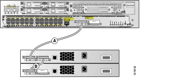
Figure 18-8 shows a stack of Cisco EtherSwitch service modules and Catalyst 3750 switches that provides full bandwidth and redundant connections.

Figure 18-8 Switch Stack with Full Bandwidth Connections

Figure 18-9 shows a stack of Cisco EtherSwitch service modules and Catalyst 3750 switches with incomplete cabling connections. This stack provides only half bandwidth and does not have redundant connections.

Figure 18-9 Switch Stack with Half Bandwidth Connections

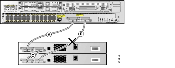
Figure 18-10 and Figure 18-11 show examples of stacks of Cisco EtherSwitch service modules and Catalyst 3750 switches with failover conditions.

In Figure 18-10, the cable in link B is bad; therefore, this stack provides only half bandwidth and does not have redundant connections.

In Figure 18-11, link B is bad, and the stack is partitioned into two separate stacks. The Cisco EtherSwitch service module 1 becomes the stack master of one stack and one of the Catalyst 3750 switches becomes the stack master of the second stack.

Figure 18-10 Example of a Stack with a Failover Condition

Figure 18-11 Example of a Partitioned Stack with a Failover Condition

Connecting to the Cisco StackWise Ports

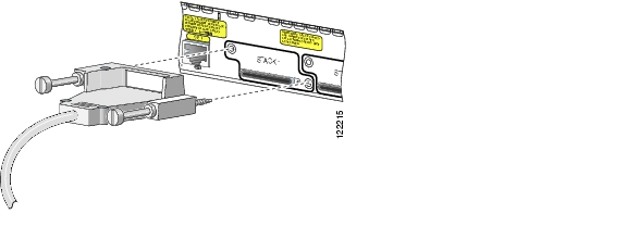
Follow these steps to connect the cable to the Cisco StackWise ports:


Step 1 Insert one end of the Cisco StackWise cable into the Cisco StackWise port. See Figure 18-12.


Note Always use a Cisco-approved Cisco StackWise cable to connect the Cisco StackWise EtherSwitch service modules.


Figure 18-12 Connecting the Cisco StackWise Cable

Step 2 Insert the other end of the cable into the connector of the other Cisco StackWise EtherSwitch service module and secure the screws tightly. See Figure 18-13.

Figure 18-13 Securing the Cisco StackWise Cable


hometocprevnextglossaryfeedbacksearchhelp

Posted: Tue Jan 29 17:04:57 PST 2008
All contents are Copyright © 1992--2008 Cisco Systems, Inc. All rights reserved.
Important Notices and Privacy Statement.