|
|

Table Of Contents
Connecting NAM Enhanced Network Modules
Shutting Down NAM Enhanced Network Modules
Connecting NAM Enhanced Network Modules
Online Insertion and Removal of Cisco NAM Enhanced Network Modules Procedure
Connecting NAM Enhanced Network Modules
This chapter describes Network Analysis Module (NAM) enhanced network modules for Cisco integrated services routers, and contains the following sections:
•
NAM Enhanced Network Modules
•
•
Tip
NAM Enhanced Network Modules
The NAM enhanced network module (NME-NAM-80S) monitors and analyzes network traffic using remote monitoring (RMON), RMON extensions for switched networks (SMON), and other management information bases (MIBs). (See Figure 26-1.)
The NAM enhanced network module ships from the factory with the following hardware preinstalled. (See Table 26-1.)
Table 26-1 Preinstalled Hardware in NAM Enhanced Network Modules
NME-NAM-80S
80 GB (SATA)
512 MB
Included
64 MB
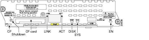
Figure 26-1 NME-NAM-80S Faceplate
f
Shutting Down NAM Enhanced Network Modules
Press the reset button on the network module faceplate for less than 2 seconds to perform a graceful shutdown of the network module before removing power from the router or before starting an online insertion and removal (OIR) sequence on the router. The application may take up to 2 minutes to fully shut down.
Caution
Connecting NAM Enhanced Network Modules
Warning
To connect NAM enhanced network modules to an external device, use a straight-through two-pair Category 5e unshielded twisted-pair (UTP) cable, and connect the RJ-45 Gigabit Ethernet port on the network module to a switch, hub, repeater, server, or other Gigabit Ethernet network device.
Note
Online Insertion and Removal of Cisco NAM Enhanced Network Modules Procedure
Some Cisco routers allow you to replace network modules without switching off the router or affecting the operation of other interfaces. This feature is called online insertion and removal (OIR). OIR of a module provides uninterrupted operation to network users, maintains routing information, and ensures session preservation.
Caution
Caution
For a description of informational and error messages that may appear on the console during this procedure, see the hardware installation guide for your router.
To perform online removal of a network module and insertion of a replacement, follow these steps, with the router in privileged EXEC mode:
Step 1
Router# service-module integrated-service-engine slot/unit sessionTrying 10.10.10.1, 2065 ... Open
Step 2
Router # prompt:root@nam.localdomain# config upload ftp://username@host/pathStep 3
Step 4
Router# service-module integrated-service-engine slot/unit session clear
Step 5
Router# service-module integrated-service-engine slot/unit shutdownStep 6
Router (config)# interface integrated-service-engine slot/unitRouter (config-if)# shutdownRouter (config-if)# exitStep 7
Step 8
Step 9
Step 10
Note
Step 11
Step 12
Step 13
Step 14
Router# service-module integrated-service-engine slot/unit sessionTrying 10.10.10.1, 2129 ... OpenStep 15
root@nam.localdomain# config network ftp://username@host/path/filenameStep 16
Step 17
Router# service-module integrated-service-engine slot/unit session clear
Additional References
For additional information, see the following documents and resources.
NAM software installation and administration, configuration, and operation
Cisco Branch Router Series (NME-NAM) Installation and
Configuration Note at http://www.cisco.com/en/US/products/sw/cscowork/ps5401/products_installation_and_configuration_guide09186a00807ee90a.htmlCisco IOS software website and reference documentation
Cisco IOS Software at http://www.cisco.com/en/US/products/sw/iosswrel/tsd_products_support_category_home.html
Technical documentation, including feedback and assistance
What's New in Cisco Product Documentation (including monthly listings of new and revised documents) at http://www.cisco.com/univercd/cc/td/doc/abtunicd/136957.htm
![]()
![]()
![]()
![]()
![]()
![]()
![]()
![]()
Posted: Wed Feb 20 17:09:06 PST 2008
All contents are Copyright © 1992--2008 Cisco Systems, Inc. All rights reserved.
Important Notices and Privacy Statement.