|
|

This chapter covers the following tasks to be done prior to initial system startup:
This chapter also covers:
Your system arrives in a box that contains the system components and electrical connectors. When you unpack the box, check the packing list that accompanies all shipments to ensure you received all the pieces you ordered. Inspect all items for shipping damage.
If anything appears damaged, or if you encounter problems when installing or configuring your system, call Cisco Systems at the number provided in the beginning of this document, or call your regional representative.
When viewed from the rear, the power cable and power switch appear on the right side of the IGS chassis. The system console port, auxiliary (AUX) port, Ethernet ports, and serial line port, if any, appear to the left of the power cable and switch. Refer to Figure 1-2 and Figure 1-3 for rear views of the IGS.
The system console port is the top, left female 25-pin D connector on the back of the chassis. The auxiliary port is located directly below the console port.
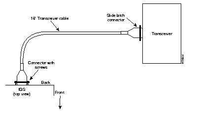
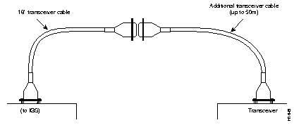
Ethernet ports are located to the right of the console port and the auxiliary port. The ports are labeled as Ethernet 0 and Ethernet 1. (Refer to Figure 1-2 and Figure 1-3.) Standard 15-pin Ethernet transceiver cables and IEEE 802.3 AUI cables can be used. An 18-inch transceiver cable is provided for each Ethernet port. This cable provides flexibility for alternate connection configurations. Three configurations are possible:
Figure 1-1 shows the transceiver cable connecting the IGS directly to the Media Access Unit (MAU) or transceiver.

Figure 1-2 shows the transceiver cable used as a flexible extension of the IGS Ethernet port allowing an Ethernet transceiver cable with a slide-latch-type connector (802.3 AUI cable) to mate with the female end of the 18-inch transceiver cable.

An Ethernet transceiver cable with thumb-screw connectors (not supplied by Cisco Systems) can be connected directly to the IGS port without using the 18-inch transceiver cable.
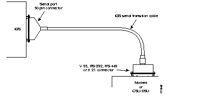
The serial interface port, if any, is located to the right of the Ethernet port on the back of the IGS. The serial port is a 50-pin D-subminiature connector. This port is Data Terminal Equipment (DTE) that expects clocking to be provided by a Channel Service Unit/Data Service Unit (CSU/DSU) or modem. A special cable, as shown in Figure 1-3, must be used for this port to function correctly. The IGS serial transition cable is available from Cisco Systems. Chapter 4 contains the specifications of the IGS serial transition cable and other cables.
Figure 1-3 shows the IGS serial transition cable connections between the IGS and a modem or CSC/DSU.

 | Caution Never operate the IGS unless the unit is completely closed. This ensures both adequate cooling and your safety. |
To prepare for initial startup and configuration, attach an RS-232 ASCII terminal to the system console port. Flow control is not possible on the console port, however, you can specify padding for output characters with the EXEC command terminal (no) padding, which sets character padding on the current terminal line. Refer to the Router Products Configuration and Reference for details on specifying padding.
Follow these steps to install the IGS system:
Step 1: Read the unpacking instructions described earlier in this section.
Step 2: Attach the cables:
n Attach your terminal to the RS-232 console port.
n Attach your network interface (Ethernet) cables or transceiver cables to the 15-pin D-type connectors on the IGS back panel. (See the previous section, "Making Connections to the IBS Chassis," for different cable options.)
n If the unit is configured with a serial port, then attach the 50-pin end of the serial cable to the synchronous serial port.
n Attach the RS-232, RS-449, V.35, or X.21 end of the cable to the Channel Service Unit/Data Service Unit (CSU/DSU) or modem.
Step 3: Plug the IGS power cord into a 3-terminal, single-phase power source which provides power within the range of 90-132 or 175-264 VAC at 47-63Hz.
Step 4: Turn on the IGS power switch.
Step 5: Check the OK light located on the left side of the IGS front panel to determine that it is on. Another indication that the unit is powered on is the sound of the fan running.
Step 6: Refer to the Router Products Getting Started publication for instructions on using the setup command facility for initial configuration.
When setting up your system, consider electromagnetic interference and, when using RS-232 connections, distance limitations.
As with all signaling systems, RS-232 can travel a limited distance at any given bit rate; generally, the slower the data rate, the greater the distance. Table 1-1 shows the standard relationship between bit rate and distance.
Data Rate | Distance (Feet) | Distance (Meters) |
|---|---|---|
| 2400 | 200 | 60 |
| 4800 | 100 | 30 |
| 9600 | 50 | 15 |
| 19200 | 25 | 7.6 |
| 38400 | 12 | 3.7 |
When you run cables for any significant distance in an electromagnetic field, interference can occur between the field and the signals on the cables. This fact has two implications for the construction of terminal plant cabling:
If you use twisted pair cables in your plant cabling with a good distribution of grounding conductors, then the plant cabling is unlikely to emit radio interference. Ground the conductor for each data signal when exceeding the distances listed in Table 1-1.
To predict and remedy strong electromagnetic interference, consult experts in radio frequency interference (RFI).
If you have cables exceeding the distances in Table 1-1, or you have cables that pass between buildings, then give special consideration to the effect of a lightning strike in your vicinity. The electromagnetic pulse caused by lightning or other high-energy phenomena can easily couple enough energy into unshielded conductors to destroy electronic devices. If you have had problems of this sort in the past, then you might want to consult experts in lightning suppression and shielding.
Most data centers cannot resolve the infrequent but potentially catastrophic problems just described without pulse meters and other special equipment. Therefore, take precautions to avoid these problems by providing a properly grounded and shielded environment, with special attention to issues of electrical surge suppression.
Each IGS includes an asynchronous system console port wired as a Data Circuit Terminating Equipment (DCE) device. The default parameters for this port are:
Refer to Table A-3 in Appendix A to specify other terminal speeds using the configuration register.
Table 1-2 lists the pinouts for the console port.
| Pin | Signal Name | Direction |
|---|---|---|
| 2 | Transmitted Data | Input |
| 3 | Received Data | Output |
| 4 | Request to Send | Shorted together |
| 5 | Clear to Send | |
| 6 | Shorted to Pin 8 | Output |
| 7 | Ground | -- |
| 8 | Carrier Detect | Output |
| 15 | Transmit Clock | Output |
| 17 | Shorted to Pin 15 | Output |
| 20 | Data Terminal Ready | Input |
An auxiliary console port is included on all IGS units. This is a DTE port to which you can attach an RS-232 port from a CSU/DSU or protocol analyzer for network access. The following table lists the pinouts for this auxiliary console port.
| Pin | Signal Name | Direction |
|---|---|---|
| 2 | Transmitted Data | Output |
| 3 | Received Data | Input |
| 4 | Request to Send | Output |
| 5 | Clear to Send | Input |
| 6 | Shorted to Pin 8 | Output |
| 7 | Ground | -- |
| 8 | Carrier Detect | Input |
| 15 | Transmit Clock | Input |
| 17 | Shorted to Pin 15 | Input |
| 20 | Data Terminal Ready | Output |
|
|