|
|

Table Of Contents
Configuring IEEE 802.1Q VLAN Encapsulation
IEEE 802.1Q VLAN Configuration
Monitoring and Verifying VLAN Operation
Configuring VLANs
This chapter describes VLAN configurations for the ML-Series card. It describes how to configure IEEE 802.1Q VLAN encapsulation. For more information about the Cisco IOS commands used in this chapter, refer to the Cisco IOS Command Reference publication.
This chapter contains the following major sections:
•
Configuring IEEE 802.1Q VLAN Encapsulation
•
•
Note
Understanding VLANs
VLANs enable network managers to group users logically rather than by physical location. A VLAN is an emulation of a standard LAN that allows secure intra-group data transfer and communication to occur without the traditional restraints placed on the network. It can also be considered a broadcast domain set up within a switch. With VLANs, switches can support more than one subnet (or VLAN) on each switch and give routers and switches the opportunity to support multiple subnets on a single physical link. A group of devices that belong to the same VLAN, but are part of different LAN segments, are configured to communicate as if they were part of the same LAN segment.
VLANs enable efficient traffic separation and provide excellent bandwidth utilization. VLANs also alleviate scaling issues by logically segmenting the physical LAN structure into different subnetworks so that packets are switched only between ports within the same VLAN. This can be very useful for security, broadcast containment, and accounting.
ML-Series software supports port-based VLANs and VLAN trunk ports, which are ports that carry the traffic of multiple VLANs. Each frame transmitted on a trunk link is tagged as belonging to only one VLAN.
ML-Series card software supports VLAN frame encapsulation through the IEEE 802.1Q standard. The Cisco Inter-Switch Link (ISL) VLAN frame encapsulation is not supported. ISL frames are broadcast at Layer 2 or dropped at Layer 3.
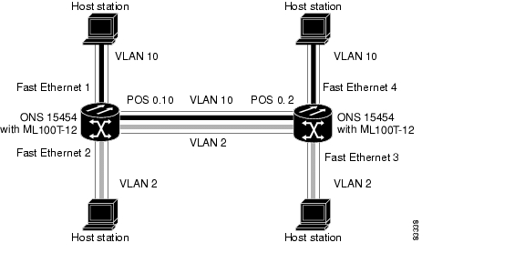
ML-Series switching supports up to 900 VLAN subinterfaces per card (for example, 200 VLANs on four interfaces uses 800 VLAN subinterfaces). A maximum of 255 logical VLANs can be bridged per card (limited by the number of bridge-groups). Each VLAN subinterface can be configured for any VLAN ID in the full 1 to 4095 range. Figure 8-1 shows a network topology in which two VLANs span two ONS 15454s with ML-Series cards.
Figure 8-1 VLANs Spanning Devices in a Network
Configuring IEEE 802.1Q VLAN Encapsulation
You can configure IEEE 802.1Q VLAN encapsulation on either type of ML-Series card interfaces, Ethernet or Packet over SONET/SDH (POS). VLAN encapsulation is not supported on POS interfaces configured with HDLC encapsulation.
The native VLAN is always VLAN ID 1 on ML-Series cards. Frames on the native VLAN are normally transmitted and received untagged. On an trunk port, all frames from VLANs other than the native VLAN are transmitted and received tagged.
To configure VLANs using IEEE 802.1Q VLAN encapsulation, perform the following procedure, beginning in global configuration mode:
Note
Note
Note
IEEE 802.1Q VLAN Configuration
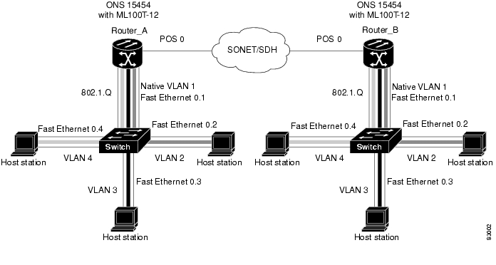
The VLAN configuration example for the ML100T-12 shown in Figure 8-2 depicts the following VLANs:
•
•
•
•
Figure 8-2 Bridging IEEE 802.1Q VLANs
Example 8-1 shows how to configure VLANs for IEEE 802.1Q VLAN encapsulation. Use this configuration for both router A and router B. The example is shown in Figure 8-2:
Example 8-1 Configure VLANs for IEEE 802.1Q VLAN Encapsulation
bridge 1 protocol ieeebridge 2 protocol ieeebridge 3 protocol ieeebridge 4 protocol ieee!!interface FastEthernet0no ip address!interface FastEthernet0.1encapsulation dot1Q 1 nativebridge-group 1!interface FastEthernet0.2encapsulation dot1Q 2bridge-group 2!interface FastEthernet0.3encapsulation dot1Q 3bridge-group 3!interface FastEthernet0.4encapsulation dot1Q 4bridge-group 4!interface POS0no ip addresscrc 32pos flag c2 1!interface POS0.1encapsulation dot1Q 1 nativebridge-group 1!interface POS0.2encapsulation dot1Q 2bridge-group 2!interface POS0.3encapsulation dot1Q 3bridge-group 3!interface POS0.4encapsulation dot1Q 4bridge-group 4Monitoring and Verifying VLAN Operation
After the VLANs are configured on the ML-Series card, you can monitor their operation by entering the privileged EXEC command show vlans vlan-id. This command displays information on all configured VLANs or on a specific VLAN (by VLAN ID number).
An example of the show vlans privileged EXEC command commands are shown here:
Example 8-2 show vlans Commands
ML1000-121#show vlansVirtual LAN ID: 1 (IEEE 802.1Q Encapsulation)vLAN Trunk Interfaces: POS1GigabitEthernet0This is configured as native Vlan for the following interface(s) :POS1GigabitEthernet0Protocols Configured: Address: Received: Transmitted:Virtual LAN ID: 5 (IEEE 802.1Q Encapsulation)vLAN Trunk Interfaces: POS1.1GigabitEthernet0.1Protocols Configured: Address: Received: Transmitted:Bridging Bridge Group 2 157 0Bridging Bridge Group 2 157 0
![]()
![]()
![]()
![]()
![]()
![]()
![]()
![]()
Posted: Tue Oct 30 11:57:29 PDT 2007
All contents are Copyright © 1992--2007 Cisco Systems, Inc. All rights reserved.
Important Notices and Privacy Statement.