|
|

Table Of Contents
Configuring IEEE 802.1Q Tunneling and Layer 2 Protocol Tunneling
Understanding IEEE 802.1Q Tunneling
Configuring IEEE 802.1Q Tunneling
IEEE 802.1Q Tunneling and Compatibility with Other Features
Configuring an IEEE 802.1Q Tunneling Port
Understanding VLAN-Transparent and VLAN-Specific Services
VLAN-Transparent and VLAN-Specific Services Configuration Example
Understanding Layer 2 Protocol Tunneling
Configuring Layer 2 Protocol Tunneling
Default Layer 2 Protocol Tunneling Configuration
Layer 2 Protocol Tunneling Configuration Guidelines
Configuring Layer 2 Tunneling on a Port
Configuring Layer 2 Tunneling Per-VLAN
Monitoring and Verifying Tunneling Status
Configuring IEEE 802.1Q Tunneling and Layer 2 Protocol Tunneling
Virtual private networks (VPNs) provide enterprise-scale connectivity on a shared infrastructure, often Ethernet-based, with the same security, prioritization, reliability, and manageability requirements of private networks. Tunneling is a feature designed for service providers who carry traffic of multiple customers across their networks and are required to maintain the VLAN and Layer 2 protocol configurations of each customer without impacting the traffic of other customers. The ML-Series cards support IEEE 802.1Q tunneling and Layer 2 protocol tunneling.
This chapter contains the following sections:
•
Understanding IEEE 802.1Q Tunneling
•
•
•
•
Understanding IEEE 802.1Q Tunneling
Business customers of service providers often have specific requirements for VLAN IDs and the number of VLANs to be supported. The VLAN ranges required by different customers in the same service-provider network might overlap, and traffic of customers through the infrastructure might be mixed. Assigning a unique range of VLAN IDs to each customer would restrict customer configurations and could easily exceed the IEEE 802.1Q specification VLAN limit of 4096.
Using the IEEE 802.1Q tunneling (QinQ) feature, service providers can use a single VLAN to support customers who have multiple VLANs. Customer VLAN IDs are preserved and traffic from different customers is segregated within the service-provider infrastructure even when they appear to be on the same VLAN. The IEEE 802.1Q tunneling expands VLAN space by using a VLAN-in-VLAN hierarchy and tagging the tagged packets. A port configured to support IEEE 802.1Q tunneling is called a tunnel port. When you configure tunneling, you assign a tunnel port to a VLAN that is dedicated to tunneling. Each customer requires a separate VLAN, but that VLAN supports all of the customer's VLANs.
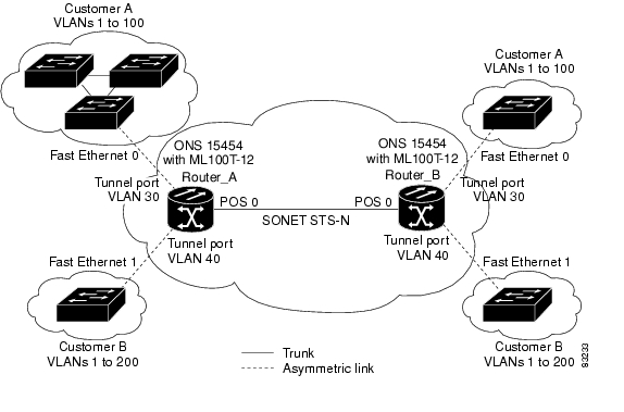
Customer traffic tagged in the normal way with appropriate VLAN IDs comes from an IEEE 802.1Q trunk port on the customer device and into a tunnel port on the ML-Series card. The link between the customer device and the ML-Series card is an asymmetric link because one end is configured as an IEEE 802.1Q trunk port and the other end is configured as a tunnel port. You assign the tunnel port interface to an access VLAN ID unique to each customer ( Figure 9-1).
Figure 9-1 IEEE 802.1Q Tunnel Ports in a Service-Provider Network
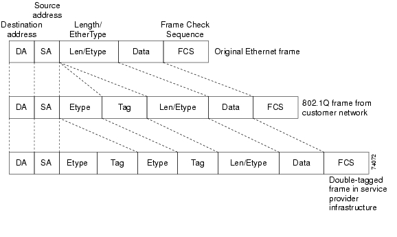
Packets coming from the customer trunk port into the tunnel port on the ML-Series card are normally IEEE 802.1Q-tagged with an appropriate VLAN ID. The tagged packets remain intact inside the ML-Series card and, when they exit the trunk port into the service provider network, are encapsulated with another layer of an IEEE 802.1Q tag (called the metro tag) that contains the VLAN ID unique to the customer. The original IEEE 802.1Q tag from the customer is preserved in the encapsulated packet. Therefore, packets entering the service-provider infrastructure are double-tagged, with the outer tag containing the customer's access VLAN ID, and the inner VLAN ID being the VLAN of the incoming traffic.
When the double-tagged packet enters another trunk port in a service provider ML-Series card, the outer tag is stripped as the packet is processed inside the switch. When the packet exits another trunk port on the same core switch, the same metro tag is again added to the packet. Figure 9-2 shows the structure of the double-tagged packet.
Figure 9-2 Normal, IEEE 802.1Q, and IEEE 802.1Q-Tunneled Ethernet Packet Formats
When the packet enters the trunk port of the service-provider egress switch, the outer tag is again stripped as the packet is processed internally on the switch. However, the metro tag is not added when it is sent out the tunnel port on the edge switch into the customer network, and the packet is sent as a normal IEEE 802.1Q-tagged frame to preserve the original VLAN numbers in the customer network.
In Figure 9-1, Customer A was assigned VLAN 30, and Customer B was assigned VLAN 40. Packets entering the ML-Series card tunnel ports with IEEE 802.1Q tags are double-tagged when they enter the service-provider network, with the outer tag containing VLAN ID 30 or 40, appropriately, and the inner tag containing the original VLAN number, for example, VLAN 100. Even if both Customers A and B have VLAN 100 in their networks, the traffic remains segregated within the service-provider network because the outer tag is different. With IEEE 802.1Q tunneling, each customer controls its own VLAN numbering space, which is independent of the VLAN numbering space used by other customers and the VLAN numbering space used by the service-provider network.
At the outbound tunnel port, the original VLAN numbers on the customer's network are recovered. If the traffic coming from a customer network is not tagged (native VLAN frames), these packets are bridged or routed as if they were normal packets, and the metro tag is added (as a single-level tag) when they exit toward the service provider network.
If the native VLAN (VLAN 1) is used in the service provider network as a metro tag, this tag must always be added to the customer traffic, even though the native VLAN ID is not normally added to transmitted frames. If the VLAN 1 metro tag is not added on frames entering the service provider network, then the customer VLAN tag appears to be the metro tag, with disastrous results. The global configuration vlan dot1q tag native command must be used to prevent this by forcing a tag to be added to VLAN 1. Avoiding the use of VLAN 1 as a metro tag transporting customer traffic is recommended to reduce the risk of misconfiguration. A best practice is to use VLAN 1 as a private management VLAN in the service provider network.
The IEEE 802.1Q class of service (COS) priority field on the added metro tag is set to zero by default, but can be modified by input or output policy maps.
Configuring IEEE 802.1Q Tunneling
This section includes the following information about configuring IEEE 802.1Q tunneling:
•
•
Note
IEEE 802.1Q Tunneling and Compatibility with Other Features
Although IEEE 802.1Q tunneling works well for Layer 2 packet switching, there are incompatibilities with some Layer 2 features and with Layer 3 switching:
•
•
•
•
•
•
•
•
Configuring an IEEE 802.1Q Tunneling Port
Beginning in privileged EXEC mode, follow these steps to configure a port as an IEEE 802.1Q tunnel port:
Note
Note
Router (config)#VLAN dot1Q tag nativeUse the no mode dot1q-tunnel interface configuration command to remove the IEEE 802.1Q tunnel from the interface.
IEEE 802.1Q Example
The following examples show how to configure the example in Figure 9-1. Example 9-1 applies to Router A, and Example 9-2 applies to Router B.
Example 9-1 Router A Configuration
bridge 30 protocol ieeebridge 40 protocol ieee!!interface FastEthernet0no ip routingno ip addressmode dot1q-tunnelbridge-group 30!interface FastEthernet1no ip addressmode dot1q-tunnelbridge-group 40!interface POS0no ip addresscrc 32pos flag c2 1!interface POS0.1encapsulation dot1Q 30bridge-group 30!interface POS0.2encapsulation dot1Q 40bridge-group 40Example 9-2 Router B Configuration
bridge 30 protocol ieeebridge 40 protocol ieee!!interface FastEthernet0no ip routingno ip addressmode dot1q-tunnelbridge-group 30!interface FastEthernet1no ip addressmode dot1q-tunnelbridge-group 40!interface POS0no ip addresscrc 32pos flag c2 1!interface POS0.1encapsulation dot1Q 30bridge-group 30!interface POS0.2encapsulation dot1Q 40bridge-group 40Understanding VLAN-Transparent and VLAN-Specific Services
The ML-Series card supports combining VLAN-transparent services and one or more VLAN-specific services on the same port. All of these VLAN-transparent and VLAN-specific services can be point-to-point or multipoint-to-multipoint.
This allows a service provider to combine a VLAN-transparent service, such as IEEE 802.1Q tunneling (QinQ), with VLAN-specific services, such as bridging specific VLANs, on the same customer port. For example, one customer VLAN can connect to Internet access and the other customer VLANs can be tunneled over a single provider VLAN to another customer site, all over a single port at each site. Table 9-1 outlines the differences between VLAN-transparent and VLAN-specific services.
Note
A VLAN-specific service on a subinterface coexists with the VLAN-transparent service, often IEEE 802.1Q tunneling, on a physical interface. VLANs configured for a VLAN-transparent service and a VLAN-specific service follow the VLAN-specific service configuration. If you need to configure 802.1Q tunneling, configure this VLAN-transparent service in the normal manner, see the "Configuring IEEE 802.1Q Tunneling" section.
A VLAN-specific service can be any service normally applicable to a VLAN. To configure an ERMS VLAN-specific service, configure the service in the normal manner.
VLAN-Transparent and VLAN-Specific Services Configuration Example
In this example, the Gigabit Ethernet interface 0 on both the ML-Series card A and ML-Series card C are the trunk ports in an IEEE 802.1Q tunnel, a VLAN-transparent service. VLAN 10 is used for the VLAN-transparent service, which would normally transport all customer VLANs on the ML-Series card A's Gigabit Ethernet interface 0. All unspecified VLANs and VLAN 1 would also be tunneled across VLAN 10.
VLAN 30 is prevented from entering the VLAN-transparent service and is instead forwarded on a specific-VLAN service, bridging Gigabit Ethernet interface 0 on ML-Series card A and Gigabit Ethernet interface 0 on ML-Series card B. Figure 9-3 is used as an example to performing configuration examples 9-3, 9-4, and 9-5.
Figure 9-3 ERMS Example
Example 9-3 applies to ML-Series card A.
Example 9-3 ML-Series Card A Configuration
hostname ML-Abridge 10 protocol rstpbridge 30 protocol ieee!!interface GigabitEthernet0no ip addressno ip route-cachemode dot1q-tunnelbridge-group 10bridge-group 10 spanning-disabled!interface GigabitEthernet0.3encapsulation dot1Q 30no ip route-cache!interface POS0no ip addressno ip route-cachecrc 32!interface POS0.1encapsulation dot1Q 10no ip route-cachebridge-group 10!interface POS0.3encapsulation dot1Q 30no ip route-cachebridge-group 30Example 9-4 applies to ML-Series card B.
Example 9-4 ML-Series Card B Configuration
hostname ML-B!bridge 10 protocol rstpbridge 30 protocol ieee!!interface GigabitEthernet0no ip address!interface GigabitEthernet0.3encapsulation dot1Q 30bridge-group 30!interface GigabitEthernet1no ip addressshutdown!interface POS0no ip addresscrc 32!interface POS0.1encapsulation dot1Q 10bridge-group 10!interface POS0.3encapsulation dot1Q 30bridge-group 30!interface POS1no ip addresscrc 32!interface POS1.1encapsulation dot1Q 10bridge-group 10!interface POS1.3encapsulation dot1Q 30bridge-group 30Example 9-5 applies to ML-Series card C.
Example 9-5 ML-Series Card C Configuration
hostname ML-Cbridge 10 protocol rstp!!interface GigabitEthernet0no ip addressno ip route-cachemode dot1q-tunnelbridge-group 10bridge-group 10 spanning-disabled!interface POS0no ip addressno ip route-cachecrc 32!interface POS0.1encapsulation dot1Q 10no ip route-cachebridge-group 10Understanding Layer 2 Protocol Tunneling
Customers at different sites connected across a service-provider network need to run various Layer 2 protocols to scale their topology to include all remote sites, as well as the local sites. Spanning Tree Protocol (STP) must run properly, and every VLAN should build a proper spanning tree that includes the local site and all remote sites across the service-provider infrastructure. Cisco Discovery Protocol (CDP) must discover neighboring Cisco devices from local and remote sites. VLAN Trunking Protocol (VTP) must provide consistent VLAN configuration throughout all sites in the customer network.
When protocol tunneling is enabled, edge switches on the inbound side of the service-provider infrastructure encapsulate Layer 2 protocol packets with a special MAC address and send them across the service-provider network. Core switches in the network do not process these packets, but forward them as normal packets. CDP, STP, or VTP Layer 2 protocol data units (PDUs) cross the service-provider infrastructure and are delivered to customer switches on the outbound side of the service-provider network. Identical packets are received by all customer ports on the same VLANs with the following results:
•
•
•
Layer 2 protocol tunneling can be used independently or to enhance IEEE 802.1Q tunneling. If protocol tunneling is not enabled on IEEE 802.1Q tunneling ports or on specific VLANs, remote switches at the receiving end of the service-provider network do not receive the PDUs and cannot properly run STP, CDP, and VTP. When protocol tunneling is enabled, Layer 2 protocols within each customer's network are totally separate from those running within the service-provider network. Customer switches on different sites that send traffic through the service-provider network with IEEE 802.1Q tunneling achieve complete knowledge of the customer's VLAN. If IEEE 802.1Q tunneling is not used, you can still enable Layer 2 protocol tunneling by connecting to the customer switch through access ports and enabling tunneling on the service-provider access port.
Configuring Layer 2 Protocol Tunneling
Layer 2 protocol tunneling (by protocol) is enabled on the tunnel ports or on specific tunnel VLANs that are connected to the customer by the edge switches of the service-provider network. ML-Series card tunnel ports are connected to customer IEEE 802.1Q trunk ports. The ML-Series card supports Layer 2 protocol tunneling for CDP, STP, and VTP at the interface and subinterface level. Multiple STP (MSTP) Tunneling support is achieved through subinterface protocol tunneling. The ML-Series cards connected to the customer switch perform the tunneling process.
When the Layer 2 PDUs that entered the inbound ML-Series switch through the tunnel port exit the switch through the trunk port into the service-provider network, the switch overwrites the customer PDU-destination MAC address with a well-known Cisco proprietary multicast address (01-00-0c-cd-cd-d0). If IEEE 802.1Q tunneling is enabled, packets are also double-tagged; the outer tag is the customer metro tag and the inner tag is the customer VLAN tag. The core switches ignore the inner tags and forward the packet to all trunk ports in the same metro VLAN. The ML-Series switches on the outbound side restore the proper Layer 2 protocol and MAC address information and forward the packets. Therefore, the Layer 2 PDUs are kept intact and delivered across the service-provider infrastructure to the other side of the customer network.
This section contains the following information about configuring Layer 2 protocol tunneling:
•
•
•
•
•
Default Layer 2 Protocol Tunneling Configuration
Table 9-2 shows the default Layer 2 protocol tunneling configuration.
Layer 2 Protocol Tunneling Configuration Guidelines
These are some configuration guidelines and operating characteristics of Layer 2 protocol tunneling:
•
•
•
•
•
•
•
•
•
Configuring Layer 2 Tunneling on a Port
Beginning in privileged EXEC mode, follow these steps to configure a port as a Layer 2 tunnel port:
Configuring Layer 2 Tunneling Per-VLAN
Beginning in privileged EXEC mode, follow these steps to configure a VLAN as a Layer 2 tunnel VLAN:
Monitoring and Verifying Tunneling Status
Table 9-3 shows the privileged EXEC commands for monitoring and maintaining IEEE 802.1Q and Layer 2 protocol tunneling.
![]()
![]()
![]()
![]()
![]()
![]()
![]()
![]()
Posted: Tue Oct 30 11:52:11 PDT 2007
All contents are Copyright © 1992--2007 Cisco Systems, Inc. All rights reserved.
Important Notices and Privacy Statement.