|
|

Table Of Contents
Bridge ID, Switch Priority, and Extended System ID
Creating the Spanning-Tree Topology
Spanning-Tree Interface States
Spanning-Tree Address Management
Spanning Tree and Redundant Connectivity
Accelerated Aging to Retain Connectivity
Port Roles and the Active Topology
Bridge Protocol Data Unit Format and Processing
Interoperability with IEEE 802.1D STP
Configuring STP and RSTP Features
Default STP and RSTP Configuration
Configuring the Switch Priority of a Bridge Group
Configuring the Forwarding-Delay Time for a Bridge Group
Configuring the Maximum-Aging Time for a Bridge Group
Verifying and Monitoring STP and RSTP Status
Configuring STP and RSTP
This chapter describes the IEEE 802.1D Spanning Tree Protocol (STP) and the ML-Series implementation of the IEEE 802.1W Rapid Spanning Tree Protocol (RSTP). It also explains how to configure STP and RSTP on the ML-Series card.
This chapter consists of these sections:
•
RSTP
•
•
•
STP Features
These sections describe how the spanning-tree features work:
•
•
•
•
•
•
STP Overview
STP is a Layer 2 link management protocol that provides path redundancy while preventing loops in the network. For a Layer 2 Ethernet network to function properly, only one active path can exist between any two stations. Spanning-tree operation is transparent to end stations, which cannot detect whether they are connected to a single LAN segment or a switched LAN of multiple segments.
When you create fault-tolerant internetworks, you must have a loop-free path between all nodes in a network. The spanning-tree algorithm calculates the best loop-free path throughout a switched Layer 2 network. Switches send and receive spanning-tree frames, called bridge protocol data units (BPDUs), at regular intervals. The switches do not forward these frames, but use the frames to construct a loop-free path.
Multiple active paths among end stations cause loops in the network. If a loop exists in the network, end stations might receive duplicate messages. Switches might also learn end-station MAC addresses on multiple Layer 2 interfaces. These conditions result in an unstable network.
Spanning tree defines a tree with a root switch and a loop-free path from the root to all switches in the Layer 2 network. Spanning tree forces redundant data paths into a standby (blocked) state. If a network segment in the spanning tree fails and a redundant path exists, the spanning-tree algorithm recalculates the spanning-tree topology and activates the standby path.
When two interfaces on a switch are part of a loop, the spanning-tree port priority and path cost settings determine which interface is put in the forwarding state and which is put in the blocking state. The port priority value represents the location of an interface in the network topology and how well it is located to pass traffic. The path cost value represents media speed.
Supported STP Instances
The ML-Series card supports the per-VLAN spanning tree (PVST+) and a maximum of 255 spanning-tree instances.
Bridge Protocol Data Units
The stable, active, spanning-tree topology of a switched network is determined by these elements:
•
•
•
When the switches in a network are powered up, each functions as the root switch. Each switch sends a configuration BPDU through all of its ports. The BPDUs communicate and compute the spanning-tree topology. Each configuration BPDU contains this information:
•
•
•
•
•
•
When a switch receives a configuration BPDU that contains superior information (lower bridge ID, lower path cost, etc.), it stores the information for that port. If this BPDU is received on the root port of the switch, the switch also forwards it with an updated message to all attached LANs for which it is the designated switch.
If a switch receives a configuration BPDU that contains inferior information to that currently stored for that port, it discards the BPDU. If the switch is a designated switch for the LAN from which the inferior BPDU was received, it sends that LAN a BPDU containing the up-to-date information stored for that port. In this way, inferior information is discarded, and superior information is propagated on the network.
A BPDU exchange results in these actions:
•
•
•
•
•
•
Election of the Root Switch
All switches in the Layer 2 network participating in the spanning tree gather information about other switches in the network through an exchange of BPDU data messages. This exchange of messages results in these actions:
•
•
•
For each VLAN, the switch with the highest switch priority (the lowest numerical priority value) is elected as the root switch. If all switches are configured with the default priority (32768), the switch with the lowest MAC address in the VLAN becomes the root switch. The switch priority value occupies the most significant bits of the bridge ID.
When you change the switch priority value, you change the probability that the switch will be elected as the root switch. Configuring a higher value decreases the probability; a lower value increases the probability.
The root switch is the logical center of the spanning-tree topology in a switched network. All paths that are not needed to reach the root switch from anywhere in the switched network are placed in the spanning-tree blocking mode.
BPDUs contain information about the sending switch and its ports, including switch and MAC addresses, switch priority, port priority, and path cost. Spanning tree uses this information to elect the root switch and root port for the switched network and the root port and designated port for each switched segment.
Bridge ID, Switch Priority, and Extended System ID
The IEEE 802.1D standard requires that each switch has an unique bridge identifier (bridge ID), which determines the selection of the root switch. Because each VLAN is considered as a different logical bridge with PVST+, the same switch must have as many different bridge IDs as VLANs configured on it. Each VLAN on the switch has a unique 8-byte bridge ID; the two most-significant bytes are used for the switch priority, and the remaining six bytes are derived from the switch MAC address.
The ML-Series card supports the IEEE 802.1T spanning-tree extensions, and some of the bits previously used for the switch priority are now used as the bridge ID. The result is that fewer MAC addresses are reserved for the switch, and a larger range of VLAN IDs can be supported, all while maintaining the uniqueness of the bridge ID. As shown in Table 7-1, the two bytes previously used for the switch priority are reallocated into a 4-bit priority value and a 12-bit extended system ID value equal to the bridge ID. In earlier releases, the switch priority is a 16-bit value.
Spanning tree uses the extended system ID, the switch priority, and the allocated spanning-tree MAC address to make the bridge ID unique for each VLAN. With earlier releases, spanning tree used one MAC address per VLAN to make the bridge ID unique for each VLAN.
Spanning-Tree Timers
Table 7-2 describes the timers that affect the entire spanning-tree performance.
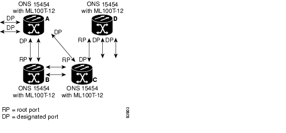
Creating the Spanning-Tree Topology
In Figure 7-1, Switch A is elected as the root switch because the switch priority of all the switches is set to the default (32768) and Switch A has the lowest MAC address. However, because of traffic patterns, number of forwarding interfaces, or link types, Switch A might not be the ideal root switch. By increasing the priority (lowering the numerical value) of the ideal switch so that it becomes the root switch, you force a spanning-tree recalculation to form a new topology with the ideal switch as the root.
Figure 7-1 Spanning-Tree Topology
When the spanning-tree topology is calculated based on default parameters, the path between source and destination end stations in a switched network might not be ideal. For instance, connecting higher-speed links to an interface that has a higher number than the root port can cause a root-port change. The goal is to make the fastest link the root port.
Spanning-Tree Interface States
Propagation delays can occur when protocol information passes through a switched LAN. As a result, topology changes can take place at different times and at different places in a switched network. When an interface transitions directly from nonparticipation in the spanning-tree topology to the forwarding state, it can create temporary data loops. Interfaces must wait for new topology information to propagate through the switched LAN before starting to forward frames. They must allow the frame lifetime to expire for forwarded frames that have used the old topology.
Each Layer 2 interface on a switch using spanning tree exists in one of these states:
•
•
•
•
•
An interface moves through these states:
1.
2.
3.
4.
5.
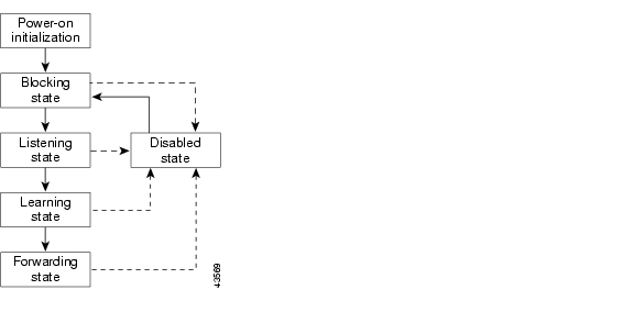
Figure 7-2 illustrates how an interface moves through the states.
Figure 7-2 Spanning-Tree Interface States
When you power up the switch, STP is enabled by default, and every interface in the switch, VLAN, or network goes through the blocking state and the transitory states of listening and learning. Spanning tree stabilizes each interface at the forwarding or blocking state.
When the spanning-tree algorithm places a Layer 2 interface in the forwarding state, this process occurs:
1.
2.
3.
4.
Blocking State
A Layer 2 interface in the blocking state does not participate in frame forwarding. After initialization, a BPDU is sent to each interface in the switch. A switch initially functions as the root until it exchanges BPDUs with other switches. This exchange establishes which switch in the network is the root or root switch. If there is only one switch in the network, no exchange occurs, the forward-delay timer expires, and the interfaces move to the listening state. An interface always enters the blocking state after switch initialization.
An interface in the blocking state performs as follows:
•
•
•
•
Listening State
The listening state is the first state a Layer 2 interface enters after the blocking state. The interface enters this state when the spanning tree determines that the interface should participate in frame forwarding.
An interface in the listening state performs as follows:
•
•
•
•
Learning State
A Layer 2 interface in the learning state prepares to participate in frame forwarding. The interface enters the learning state from the listening state.
An interface in the learning state performs as follows:
•
•
•
•
Forwarding State
A Layer 2 interface in the forwarding state forwards frames. The interface enters the forwarding state from the learning state.
An interface in the forwarding state performs as follows:
•
•
•
•
Disabled State
A Layer 2 interface in the disabled state does not participate in frame forwarding or in the spanning tree. An interface in the disabled state is nonoperational.
A disabled interface performs as follows:
•
•
•
Spanning-Tree Address Management
IEEE 802.1D specifies 17 multicast addresses, ranging from 0x00180C2000000 to 0x0180C2000010, to be used by different bridge protocols. These addresses are static addresses that cannot be removed.
The ML-Series card switches supported BPDUs (0x0180C2000000 and 01000CCCCCCD) when they are being tunneled via the protocol tunneling feature.
STP and IEEE 802.1Q Trunks
When you connect a Cisco switch to a non-Cisco device through an IEEE 802.1Q trunk, the Cisco switch uses PVST+ to provide spanning-tree interoperability. PVST+ is automatically enabled on IEEE 802.1Q trunks after users assign a protocol to a bridge group. The external spanning-tree behavior on access ports and Inter-Switch Link (ISL) trunk ports is not affected by PVST+.
For more information on IEEE 802.1Q trunks, see Chapter 8, "Configuring VLANs."
Spanning Tree and Redundant Connectivity
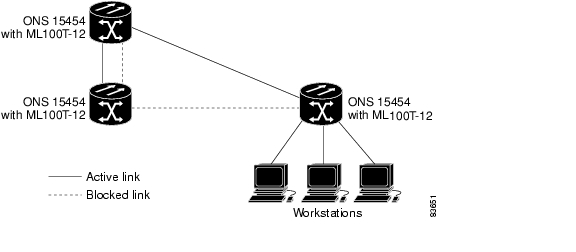
You can create a redundant backbone with spanning tree by connecting two switch interfaces to another device or to two different devices. Spanning tree automatically disables one interface but enables it if the other one fails, as shown in Figure 7-3. If one link is high speed and the other is low speed, the low-speed link is always disabled. If the speeds are the same, the port priority and port ID are added together, and spanning tree disables the link with the lowest value.
Figure 7-3 Spanning Tree and Redundant Connectivity
You can also create redundant links between switches by using EtherChannel groups. For more information, see Chapter 10, "Configuring Link Aggregation."
Accelerated Aging to Retain Connectivity
The default for aging dynamic addresses is 5 minutes, which is the default setting of the bridge bridge-group-number aging-time global configuration command. However, a spanning-tree reconfiguration can cause many station locations to change. Because these stations could be unreachable for 5 minutes or more during a reconfiguration, the address-aging time is accelerated so that station addresses can be dropped from the address table and then relearned.
Because each VLAN is a separate spanning-tree instance, the switch accelerates aging on a per-VLAN basis. A spanning-tree reconfiguration on one VLAN can cause the dynamic addresses learned on that VLAN to be subject to accelerated aging. Dynamic addresses on other VLANs can be unaffected and remain subject to the aging interval entered for the switch.
RSTP
RSTP provides rapid convergence of the spanning tree. It improves the fault tolerance of the network because a failure in one instance (forwarding path) does not affect other instances (forwarding paths). The most common initial deployment of RSTP is in the backbone and distribution layers of a Layer 2 switched network; this deployment provides the highly available network required in a service-provider environment.
RSTP improves the operation of the spanning tree while maintaining backward compatibility with equipment that is based on the (original) IEEE 802.1D spanning tree.
RSTP takes advantage of point-to-point wiring and provides rapid convergence of the spanning tree. Reconfiguration of the spanning tree can occur in less than 2 second (in contrast to 50 seconds with the default settings in the IEEE 802.1D spanning tree), which is critical for networks carrying delay-sensitive traffic such as voice and video.
These sections describe how RSTP works:
•
•
•
Supported RSTP Instances
The ML Series supports per-VLAN rapid spanning tree (PVRST) and a maximum of 255 rapid spanning-tree instances.
Port Roles and the Active Topology
The RSTP provides rapid convergence of the spanning tree by assigning port roles and by determining the active topology. The RSTP builds upon the IEEE 802.1D STP to select the switch with the highest switch priority (lowest numerical priority value) as the root switch as described in "Election of the Root Switch" section. Then the RSTP assigns one of these port roles to individual ports:
•
•
•
•
•
A port with the root or a designated port role is included in the active topology. A port with the alternate or backup port role is excluded from the active topology.
In a stable topology with consistent port roles throughout the network, the RSTP ensures that every root port and designated port immediately transition to the forwarding state while all alternate and backup ports are always in the discarding state (equivalent to blocking in IEEE 802.1D). The port state controls the operation of the forwarding and learning processes. Table 7-3 provides a comparison of IEEE 802.1D and RSTP port states.
Caution
Note
Rapid Convergence
The RSTP provides for rapid recovery of connectivity following the failure of switch, a switch port, or a LAN. It provides rapid convergence for new root ports, and ports connected through point-to-point links as follows:
•
•
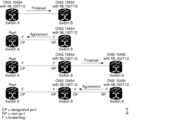
As shown in Figure 7-4, Switch A is connected to Switch B through a point-to-point link, and all of the ports are in the blocking state. Assume that the priority of Switch A is a smaller numerical value than the priority of Switch B. Switch A sends a proposal message (a configuration BPDU with the proposal flag set) to Switch B, proposing itself as the designated switch.
After receiving the proposal message, Switch B selects as its new root port the port from which the proposal message was received, forces all non edge ports to the blocking state, and sends an agreement message (a BPDU with the agreement flag set) through its new root port.
After receiving an agreement message from Switch B, Switch A also immediately transitions its designated port to the forwarding state. No loops in the network are formed because Switch B blocked all of its non edge ports and because there is a point-to-point link between Switches A and B.
When Switch C is connected to Switch B, a similar set of handshaking messages are exchanged. Switch C selects the port connected to Switch B as its root port, and both ends immediately transition to the forwarding state. With each iteration of this handshaking process, one more switch joins the active topology. As the network converges, this proposal-agreement handshaking progresses from the root toward the leaves of the spanning tree.
The switch determines the link type from the port duplex mode: a full-duplex port is considered to have a point-to-point connection; a half-duplex port is considered to have a shared connection.
Figure 7-4 Proposal and Agreement Handshaking for Rapid Convergence
Synchronization of Port Roles
When the switch receives a proposal message on one of its ports and that port is selected as the new root port, the RSTP forces all other ports to synchronize with the new root information. The switch is synchronized with superior root information received on the root port if all other ports are synchronized.
If a designated port is in the forwarding state, it transitions to the blocking state when the RSTP forces it to synchronize with new root information. In general, when the RSTP forces a port to synchronize with root information and the port does not satisfy any of the above conditions, its port state is set to blocking.
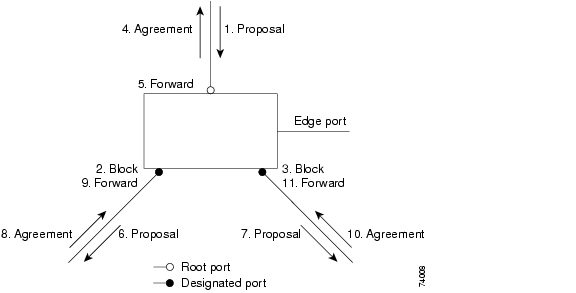
After ensuring all of the ports are synchronized, the switch sends an agreement message to the designated switch corresponding to its root port. When the switches connected by a point-to-point link are in agreement about their port roles, the RSTP immediately transitions the port states to forwarding. The sequence of events is shown in Figure 7-5.
Figure 7-5 Sequence of Events During Rapid Convergence
Bridge Protocol Data Unit Format and Processing
The RSTP BPDU format is the same as the IEEE 802.1D BPDU format except that the protocol version is set to 2. A new Length field is set to zero, which means that no version 1 protocol information is present. Table 7-4 shows the RSTP flag fields.
The sending switch sets the proposal flag in the RSTP BPDU to propose itself as the designated switch on that LAN. The port role in the proposal message is always set to the designated port.
The sending switch sets the agreement flag in the RSTP BPDU to accept the previous proposal. The port role in the agreement message is always set to the root port.
The RSTP does not have a separate topology change notification (TCN) BPDU. It uses the topology change (TC) flag to show the topology changes. However, for interoperability with IEEE 802.1D switches, the RSTP switch processes and generates TCN BPDUs.
The learning and forwarding flags are set according to the state of the sending port.
Processing Superior BPDU Information
If a port receives superior root information (lower bridge ID, lower path cost, etc.) than currently stored for the port, the RSTP triggers a reconfiguration. If the port is proposed and is selected as the new root port, RSTP forces all the other ports to synchronize.
If the BPDU received is an RSTP BPDU with the proposal flag set, the switch sends an agreement message after all of the other ports are synchronized. If the BPDU is an IEEE 802.1D BPDU, the switch does not set the proposal flag and starts the forward-delay timer for the port. The new root port requires twice the forward-delay time to transition to the forwarding state.
If the superior information received on the port causes the port to become a backup or alternate port, RSTP sets the port to the blocking state but does not send the agreement message. The designated port continues sending BPDUs with the proposal flag set until the forward-delay timer expires, at which time the port transitions to the forwarding state.
Processing Inferior BPDU Information
If a designated port receives an inferior BPDU (higher bridge ID, higher path cost, etc.) than currently stored for the port with a designated port role, it immediately replies with its own information.
Topology Changes
This section describes the differences between the RSTP and the IEEE 802.1D in handling spanning-tree topology changes.
•
•
•
This behavior is only required to support IEEE 802.1D switches. The RSTP BPDUs never have the topology change acknowledgement bit set.
•
•
When a port is initialized, the timer is started (which specifies the minimum time during which RSTP BPDUs are sent), and RSTP BPDUs are sent. While this timer is active, the switch processes all BPDUs received on that port and ignores the protocol type.
If the switch receives an IEEE 802.1D BPDU after the port's migration-delay timer has expired, it assumes that it is connected to an IEEE 802.1D switch and starts using only IEEE 802.1D BPDUs. However, if the RSTP switch is using IEEE 802.1D BPDUs on a port and receives an RSTP BPDU after the timer has expired, it restarts the timer and starts using RSTP BPDUs on that port.
Interoperability with IEEE 802.1D STP
A switch running RSTP supports a built-in protocol migration mechanism that enables it to interoperate with legacy IEEE 802.1D switches. If this switch receives a legacy IEEE 802.1D configuration BPDU (a BPDU with the protocol version set to 0), it sends only IEEE 802.1D BPDUs on that port.
However, the switch does not automatically revert to the RSTP mode if it no longer receives IEEE 802.1D BPDUs because it cannot determine whether the legacy switch has been removed from the link unless the legacy switch is the designated switch. Also, a switch might continue to assign a boundary role to a port when the switch to which this switch is connected has joined the region.
Configuring STP and RSTP Features
These sections describe how to configure spanning-tree features:
•
•
•
•
•
Default STP and RSTP Configuration
Table 7-5 shows the default STP and RSTP configuration.
Disabling STP and RSTP
STP is enabled by default on native VLAN 1 and on all newly created VLANs up to the specified spanning-tree limit of 255. Disable STP only if you are sure there are no loops in the network topology.
Caution
Caution
Beginning in privileged EXEC mode, follow these steps to disable STP or RSTP on a per-VLAN basis:
To reenable STP, use the no bridge-group bridge-group-number spanning disabled interface-level configuration command.
Configuring the Root Switch
The switch maintains a separate spanning-tree instance for each active VLAN configured on it. A bridge ID, consisting of the switch priority and the switch MAC address, is associated with each instance. For each VLAN, the switch with the lowest bridge ID becomes the root switch for that VLAN.
Note
Configuring the Port Priority
If a loop occurs, spanning tree uses the port priority when selecting an interface to put into the forwarding state. You can assign higher priority values (lower numerical values) to interfaces that you want selected first, and lower priority values (higher numerical values) that you want selected last. If all interfaces have the same priority value, spanning tree puts the interface with the lowest interface number in the forwarding state and blocks the other interfaces.
Beginning in privileged EXEC mode, follow these steps to configure the port priority of an interface:
To return the interface to its default setting, use the no bridge-group id bridge-group-number priority- value command.
Configuring the Path Cost
The spanning-tree path cost default value is derived from the media speed of an interface. If a loop occurs, spanning tree uses cost when selecting an interface to put in the forwarding state. You can assign lower cost values to interfaces that you want selected first and higher cost values to interfaces that you want selected last. If all interfaces have the same cost value, spanning tree puts the interface with the lowest interface number in the forwarding state and blocks the other interfaces.
Beginning in privileged EXEC mode, follow these steps to configure the cost of an interface:
Note
To return the interface to its default setting, use the no bridge-group bridge-group-number path-cost cost command.
Configuring the Switch Priority of a Bridge Group
You can configure the switch priority and make it more likely that the switch will be chosen as the root switch.
Beginning in privileged EXEC mode, follow these steps to configure the switch priority of a bridge group:
To return the switch to its default setting, use the no bridge bridge-group-number priority priority command.
Configuring the Hello Time
You can configure the interval between the generation of configuration messages by the root switch by changing the hello time.
Beginning in privileged EXEC mode, follow these steps to configure the hello time of a bridge group:
To return the switch to its default setting, use the no bridge bridge-group-number hello-time seconds command.
Configuring the Forwarding-Delay Time for a Bridge Group
Beginning in privileged EXEC mode, follow these steps to configure the forwarding-delay time for a bridge group:
To return the switch to its default setting, use the no bridge bridge-group-number forward-time seconds command.
Configuring the Maximum-Aging Time for a Bridge Group
Beginning in privileged EXEC mode, follow these steps to configure the maximum-aging time for a bridge group:
To return the switch to its default setting, use the no bridge bridge-group-number max-age seconds command.
Verifying and Monitoring STP and RSTP Status
To display the STP or RSTP status, use one or more of the privileged EXEC commands in Table 7-6:
Note
Examples of the show spanning-tree privileged EXEC command commands are shown here:
Example 7-1 show spanning-tree Commands
Router# show spanning-tree briefBridge group 1Spanning tree enabled protocol ieeeRoot ID Priority 32769Address 0005.9a39.6634This bridge is the rootHello Time 2 sec Max Age 20 sec Forward Delay 15 secBridge ID Priority 32769 (priority 32768 sys-id-ext 1)Address 0005.9a39.6634Hello Time 2 sec Max Age 20 sec Forward Delay 15 secAging Time 300Interface Role Sts Cost Prio.Nbr Type---------------- ---- --- --------- -------- --------------------------------Fa0 Desg FWD 19 128.3 P2pPO0 Desg FWD 3 128.20 P2pRouter# show spanning-tree detailBridge group 1 is executing the ieee compatible Spanning Tree protocolBridge Identifier has priority 32768, sysid 1, address 0005.9a39.6634Configured hello time 2, max age 20, forward delay 15We are the root of the spanning treeTopology change flag not set, detected flag not setNumber of topology changes 2 last change occurred 00:16:45 agofrom POS0Times: hold 1, topology change 35, notification 2hello 2, max age 20, forward delay 15Timers: hello 0, topology change 0, notification 0, aging 300Port 3 (FastEthernet0) of Bridge group 1 is forwardingPort path cost 19, Port priority 128, Port Identifier 128.3.Designated root has priority 32769, address 0005.9a39.6634Designated bridge has priority 32769, address 0005.9a39.6634Designated port id is 128.3, designated path cost 0Timers: message age 0, forward delay 0, hold 0Number of transitions to forwarding state: 1Link type is point-to-point by defaultBPDU: sent 641, received 0Port 20 (POS0) of Bridge group 1 is forwardingPort path cost 3, Port priority 128, Port Identifier 128.20.Designated root has priority 32769, address 0005.9a39.6634Designated bridge has priority 32769, address 0005.9a39.6634Designated port id is 128.20, designated path cost 0Timers: message age 0, forward delay 0, hold 0Number of transitions to forwarding state: 6Link type is point-to-point by defaultBPDU: sent 582, received 15Router# show spanning-tree interface fast 0Bridge Group Role Sts Cost Prio.Nbr Type---------------- ---- --- --------- -------- --------------------------------Bridge group 1 Desg FWD 19 128.3 P2pRouter# show spanning-tree interface pos 0Bridge Group Role Sts Cost Prio.Nbr Type---------------- ---- --- --------- -------- --------------------------------Bridge group 1 Desg FWD 3 128.20 P2pRouter# show spanning-tree summary totalsSwitch is in pvst modeRoot bridge for: Bridge group 1Name Blocking Listening Learning Forwarding STP Active---------------------- -------- --------- -------- ---------- ----------1 bridge 0 0 0 2 2
![]()
![]()
![]()
![]()
![]()
![]()
![]()
![]()
Posted: Tue Oct 30 11:53:05 PDT 2007
All contents are Copyright © 1992--2007 Cisco Systems, Inc. All rights reserved.
Important Notices and Privacy Statement.