|
|

Table Of Contents
Configuring Quality of Service
Priority Mechanism in IP and Ethernet
IP Precedence and Differentiated Services Code Point
Marking and Discarding with a Policer
Control Packets and L2 Tunneled Protocols
Attaching a Traffic Policy to an Interface
Monitoring and Verifying QoS Configuration
Traffic Classes Defined Example
Traffic Policy Created Example
class-map match-any and class-map match-all Commands Example
ML-Series CoS-Based QoS Example
Understanding Multicast QoS and Priority Multicast Queuing
Multicast Priority Queuing QoS Restrictions
Configuring Multicast Priority Queuing QoS
Understanding CoS-Based Packet Statistics
Configuring CoS-Based Packet Statistics
IP SLA Restrictions on the ML-Series
Configuring Quality of Service
This chapter describes the Quality of Service (QoS) features built into your ML-Series card and how to map QoS scheduling at both the system and interface levels.
This chapter contains the following major sections:
•
Monitoring and Verifying QoS Configuration
•
•
•
•
The ML-Series card employs the Cisco IOS Modular QoS command-line interface (CLI), known as the MQC. For more information on general MQC configuration, refer to the following Cisco IOS documents:
•
•
Understanding QoS
QoS is the ability of the network to provide better or special treatment to a set of services to the detriment of less critical services. The ML-Series card uses QoS to dynamically allocate transmission bandwidth for the different services it multiplexes onto the SONET/SDH circuit. Through QoS, you can configure the ML-Series card to provide different levels of treatment to the different services. The different levels are defined through the service elements of bandwidth, including loss and delay. A service-level agreement (SLA) is a guaranteed level of these service elements.
The QoS mechanism has three basic steps. It classifies types of traffic, specifies what action to take against a type of traffic, and specifies where the action should take place. The following sections explains how the ML-Series card accomplishes these steps for unicast traffic. QoS for priority-multicast traffic and traffic with unknown destination addresses is handled with a different mechanism, detailed in the "Understanding Multicast QoS and Priority Multicast Queuing" section.
Priority Mechanism in IP and Ethernet
For any QoS service to be applied to data, there must be a way to mark or identify an IP packet or an Ethernet frame. When identified, a specific priority can be assigned to each individual IP packet or Ethernet frame. The IP Precedence or the IP Differentiated Services Code Point (DSCP) field prioritizes the IP packets, and the Ethernet class of service (IEEE 802.1p defined class of service [CoS]) is used for the Ethernet frames. IP precedence and Ethernet CoS are further described in the following sections.
IP Precedence and Differentiated Services Code Point
IP precedence uses the three precedence bits in the IPv4 header's ToS (type of service) field to specify class of service for each IP packet (RFC 1122). The most significant three bits on the IPv4 ToS field provides up to eight distinct classes, of which six are used for classifying services and the remaining two are reserved. On the edge of the network, the IP precedence is assigned by the client device or the router, so that each subsequent network element can provide services based on the determined policy or the SLA.
IP DSCP uses the six bits in the IPv4 header to specify class of service for each IP packet (RFC 2474). Figure 14-1 illustrates IP precedence and DSCP. The DSCP field classifies packets into any of the 64 possible classes. On the network edge, the IP DSCP is assigned by the client device or the router, so that each subsequent network element can provide services based on the determined policy or the SLA.
Figure 14-1 IP Precedence and DSCP
Ethernet CoS
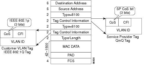
Ethernet CoS refers to three bits within a four byte IEEE 802.1Q (VLAN) header used to indicate the priority of the Ethernet frame as it passes through a switched network. The CoS bits in the IEEE 802.1Q header are commonly referred to as the IEEE 802.1p bits. There are three CoS bits that provide eight classes, matching the number delivered by IP precedence. In many real-world networks, a packet might traverse both Layer 2 and Layer 3 domains. To maintain QoS across the network, the IP ToS can be mapped to the Ethernet CoS and vice versa, for example, in linear or one-to-one mapping, because each mechanism supports eight classes. Similarly, a set of DSCP values (64 classes) can be mapped into each of the eight individual Ethernet CoS values. Figure 14-2 shows an IEEE 802.1Q Ethernet frame, which consists of a 2-byte Ethertype and a 2-byte tag (IEEE 802.1Q Tag) on the Ethernet protocol header.
Figure 14-2 Ethernet Frame and the CoS Bit (IEEE 802.1p)
ML-Series QoS
The ML-Series QoS classifies each packet in the network based on its input interface, bridge group (VLAN), Ethernet CoS, IP precedence, IP DSCP, or resilient packet ring (RPR)-CoS. After they are classified into class flows, further QoS functions can be applied to each packet as it traverses the card. Figure 14-3 illustrates the ML-Series QoS flow.
Figure 14-3 ML-Series QoS Flow
Policing provided by the ML-Series card ensures that attached equipment does not submit more than a predefined amount of bandwidth (Rate Limiting) into the network. The policing feature can be used to enforce the committed information rate (CIR) and the peak information rate (PIR) available to a customer at an interface. Policing also helps characterize the statistical nature of the information allowed into the network so that traffic engineering can more effectively ensure that the amount of committed bandwidth is available on the network, and the peak bandwidth is over-subscribed with an appropriate ratio. The policing action is applied per classification.
Priority marking can set the Ethernet IEEE 802.1p CoS bits or RPR-CoS bits as they exit the ML-Series card. The marking feature operates on the outer IEEE 802.1p tag, and provides a mechanism for tagging packets at the ingress of a QinQ packet. The subsequent network elements can provide QoS based only on this service-provider-created QoS indicator.
Per-class flow queuing enables fair access to excess network bandwidth, allows allocation of bandwidth to support SLAs, and ensures that applications with high network resource requirements are adequately served. Buffers are allocated to queues dynamically from a shared resource pool. The allocation process incorporates the instantaneous system load as well as the allocated bandwidth to each queue to optimize buffer allocation. Congestion management on the ML-Series is performed through a tail drop mechanism along with discard eligibility on the egress scheduler.
The ML-Series uses a Weighted Deficit Round Robin (WDRR) scheduling process to provide fair access to excess bandwidth as well as guaranteed throughput to each class flow.
Admission control is a process that is invoked each time that service is configured on the ML-Series card to ensure that QoS resources are not overcommitted. In particular, admission control ensures that no configurations are accepted, where a sum of the committed bandwidths on an interface exceeds total bandwidth on the interface.
Classification
Classification can be based on any single packet classification criteria or a combination (logical AND and OR). A total of 254 classes, not including the class default, can be defined on the card. Classification of packets is configured using the Modular CLI class-map command. For traffic transiting the RPR, only the input interface and/or the RPR-CoS can be used as classification criteria.
Policing
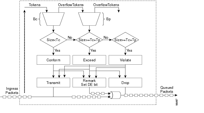
Dual leaky bucket policer is a process where the first bucket (CIR bucket) is filled with tokens at a known rate (CIR), which is a parameter that can be configured by the operator. Figure 14-4 illustrates the dual leaky bucket policer model. The tokens fill the bucket up to a maximum level, which is the amount of burstable committed (BC) traffic on the policer. The nonconforming packets of the first bucket are the overflow packets, which are passed to the second leaky bucket (the PIR bucket). The second leaky bucket is filled with these tokens at a known rate (PIR), which is a parameter that can be configured by the operator. The tokens fill the PIR bucket up to a maximum level (BP), which is the amount of peak burstable traffic on the policer. The nonconform packets of the second bucket are the overflow packets, which can be dropped or marked according to the policer definition.
On the dual leaky bucket policer, the packets conforming to the CIR are conform packets, the packets not conforming to CIR but conforming to PIR are exceed packets, and the packets not conforming to either the PIR or CIR are violate packets.
Figure 14-4 Dual Leaky Bucket Policer Model
Marking and Discarding with a Policer
On the ML-Series card's policer, the conform packets can be transmitted or marked and transmitted. The exceed packets can be transmitted, marked and transmitted, or dropped. The violating packets can be transmitted, marked and transmitted, or dropped. The primary application of the dual-rate or three-color policer is to mark the conform packets with CoS bit 2l, mark the exceed packet with CoS bit 1, and discard the violated packets so all the subsequent network devices can implement the proper QoS treatment per frame/packet basis based on these priority marking without knowledge of each SLA.
In some cases, it might be desirable to discard all traffic of a specific ingress class. This can be accomplished by using a police command of the following form with the class: police 96000 conform-action drop exceed-action drop.
If a marked packet has a provider-supplied Q-tag inserted before transmission, the marking only affects the provider Q-tag. If a Q-tag is received, it is re-marked. If a marked packet is transported over the RPR ring, the marking also affects the RPR-CoS bit.
If a Q-tag is inserted (QinQ), the marking affects the added Q-tag. If the ingress packet contains a Q-tag and is transparently switched, the existing Q-tag is marked. In the case of a packet without any Q-tag, the marking does not have any significance.
The local scheduler treats all nonconforming packets as discard eligible regardless of their CoS setting or the global cos commit definition. For RPR implementation, the discard eligible (DE) packets are marked using the DE bit on the RPR header. The discard eligibility based on the CoS commit or the policing action is local to the ML-Series card scheduler, but it is global for the RPR ring.
Queuing
ML-Series card queuing uses a shared buffer pool to allocate memory dynamically to different traffic queues. The ML-Series card uses a total of 12 MB of memory for the buffer pool. Ethernet ports share 6 MB of the memory, and packet-over-SONET/SDH (POS) ports share the remaining 6 MBs of memory. Memory space is allocated in 1500-byte increments.
Each queue has an upper limit on the allocated number of buffers based on the class bandwidth assignment of the queue and the number of queues configured. This upper limit is typically 30 percent to 50 percent of the shared buffer capacity. Dynamic buffer allocation to each queue can be reduced based on the number of queues that need extra buffering. The dynamic allocation mechanism provides fairness in proportion to service commitments as well as optimization of system throughput over a range of system traffic loads.
The Low Latency Queue (LLQ) is defined by setting the weight to infinity or by committing 100 percent of the bandwidth. When a LLQ is defined, a policer should also be defined on the ingress for that specific class to limit the maximum bandwidth consumed by the LLQ; otherwise there is a potential risk of LLQ occupying the whole bandwidth and starving the other unicast queues.
The ML-Series includes support for 400 user-definable queues, which are assigned according to the classification and bandwidth allocation definition. The classification used for scheduling classifies the frames/packet after the policing action, so if the policer is used to mark or change the CoS bits of the ingress frames/packet, the new values are applicable for the classification of traffic for queuing and scheduling. The ML-Series provides buffering for 4000 packets.
Scheduling
Scheduling is provided by a series of schedulers that perform a WDRR as well as by priority scheduling mechanisms from the queued traffic associated with each egress port.
Though ordinary round robin servicing of queues can be done in constant time, unfairness occurs when different queues use different packet sizes. Deficit Round Robin (DRR) scheduling solves this problem. If a queue was not able to send a packet in its previous round because its packet size was too large, the remainder from the previous amount of credits a queue gets in each round (quantum) is added to the quantum for the next round.
WDRR extends the quantum idea from the DRR to provide weighted throughput for each queue. Different queues have different weights, and the quantum assigned to each queue in its round is proportional to the relative weight of the queue among all the queues serviced by that scheduler.
Weights are assigned to each queue as a result of the service provisioning process. When coupled with policing and policy mapping provisioning, these weights and the WDRR scheduling process ensure that QoS commitments are provided to each service flow.
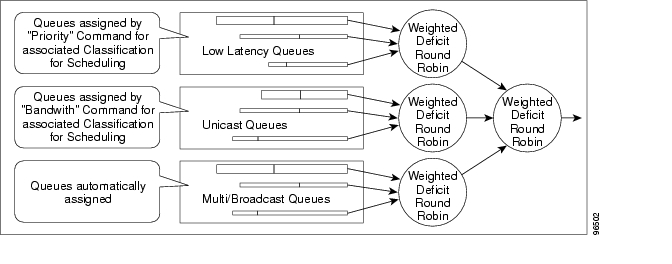
Figure 14-5 illustrates the ML-Series card's queuing and scheduling.
Figure 14-5 Queuing and Scheduling Model
The weighting structure allows traffic to be scheduled at 1/2048 of the port rate. This equates to approximately 488 kbps for traffic exiting a Gigabit Ethernet port, approximately 293 kbps for traffic exiting an OC-12c port, and approximately 49 kbps for traffic exiting a FastEthernet port.
The unicast queues are created as the output service policy implementation on the egress ports. Each unicast queue is assigned with a committed bandwidth and the weight of the queue is determined by the normalization of committed bandwidth of all defined unicast queues for that port. The traffic beyond the committed bandwidth on any queue is treated by the scheduler according to the relative weight of the queue.
The LLQ is created as the output service policy implementation on the egress ports. Each LLQ queue is assigned with a committed bandwidth of 100 percent and is served with lower latency. To limit the bandwidth usage by the LLQ, a strict policer needs to be implemented on the ingress for the LLQ traffic classes.
The DE allows some packets to be treated as committed and some as discard-eligible on the scheduler. For Ethernet frames, the CoS (IEEE 802.1p) bits are used to identify committed and discard eligible packets, where the RPR-CoS and the DE bits are used for RPR traffic. When congestion occurs and a queue begins to fill, the DE packets hit a lower tail-drop threshold than the committed packets. Committed packets are not dropped until the total committed load exceeds the interface output. The tail-drop thresholds adjust dynamically in the card to maximize use of the shared buffer pool while guaranteeing fairness under all conditions.
Control Packets and L2 Tunneled Protocols
The control packets originated by the ML-Series card have a higher priority than data packets. The external Layer 2 and Layer 3 control packets are handled as data packets and assigned to broadcast queues. Bridge protocol data unit (BPDU) prioritization in the ML-Series card gives Layer 2-tunneled BPDU sent out the multicast/broadcast queue a higher discard value and therefore a higher priority than than other packets in the multicast/broadcast queue. The Ethernet CoS (IEEE 802.1p) for Layer 2-tunneled protocols can be assigned by the ML-Series card.
Egress Priority Marking
Egress priority marking allows the operator to assign the IEEE 802.1p CoS bits of packets that exit the card. This marking allows the operator to use the CoS bits as a mechanism for signaling to downstream nodes the QoS treatment the packet should be given. This feature operates on the outer-most IEEE 802.1p CoS field. When used with the QinQ feature, priority marking allows the user traffic (inner Q-tag) to traverse the network transparently, while providing a means for the network to internally signal QoS treatment at Layer 2.
Priority marking follows the classification process, and therefore any of the classification criteria identified earlier can be used as the basis to set the outgoing IEEE 802.1p CoS field. For example, a specific CoS value can be mapped to a specific bridge group.
Priority marking is configured using the MQC set-cos command. If packets would otherwise leave the card without an IEEE 802.1Q tag, then the set-cos command has no effect on that packet. If an IEEE 802.1Q tag is inserted in the packet (either a normal tag or a QinQ tag), the inserted tag has the set-cos priority. If an IEEE 802.1Q tag is present on packet ingress and retained on packet egress, the priority of that tag is modified. If the ingress interface is a QinQ access port and the set-cos policy-map classifies based on ingress tag priority, this classifies based on the user priority. This is a way to allow the user-tag priority to determine the SP tag priority. When a packet does not match any set-cos policy-map, the priority of any preserved tag is unchanged and the priority of any inserted IEEE 802.1Q tag is set to 0.
The set-cos command on the output service policy is only applied to unicast traffic. Priority marking for multicast/broadcast traffic can only be achieved by the set-cos action of the policing process on the input service policy.
Ingress Priority Marking
Ingress priority marking can be done for all input packets of a port, for all input packets matching a classification, or based on a measured rate. Marking of all packets of an input class can also be done with a policing command of the form police 96000 conform-action set-cos-transmit exceed-action set-cos-transmit. Using this command with a policy map that contains only the "class-default" will mark all ingress packets to the value. Rate based priority marking is discussed in the section "Marking and Discarding with a Policer" section.
QinQ Implementation
The hierarchical VLAN or IEEE 802.1Q tunneling feature enables the service provider to transparently carry the customer VLANs coming from any specific port (UNI) and transport them over the service provider network. This feature is also known as QinQ, which is performed by adding an additional IEEE 802.1Q tag on every customer frame.
Using the QinQ feature, service providers can use a single VLAN to support customers with multiple VLANs. QinQ preserves customer VLAN IDs and segregates traffic from different customers within the service-provider infrastructure, even when traffic from different customers originally shared the same VLAN ID. The QinQ also expands VLAN space by using a VLAN-in-VLAN hierarchy and tagging the tagged packets. When the service provider (SP) tag is added, the QinQ network typically loses any visibility to the IP header or the customer Ethernet IEEE 802.1Q tag on the QinQ encapsulated frames.
On the ML-Series cards, the QinQ access ports (IEEE 802.1Q tunnel ports or QinQ UNI ports) have visibility to the customer CoS and the IP precedence or IP DSCP values; therefore, the SP tag can be assigned with the proper CoS bit, which would reflect the customer IP precedence, IP DSCP, or CoS bits. In the QinQ network, the QoS is then implemented based on the IEEE 802.1p bit of the SP tag. The ML-Series cards do not have visibility into the customer CoS, IP precedence, or DSCP values after the packet is double-tagged (because it is beyond the entry point of the QinQ service).
Figure 14-6 illustrates the QinQ implementation on the ML-Series card.
Figure 14-6 QinQ
The ML-Series cards can be used as the IEEE 802.1Q tunneling device for the QinQ network and also provide the option to copy the customer frame's CoS bit into the CoS bit of the added QinQ tag. This way, the service provider QinQ network can be fully aware of the necessary QoS treatment for each individual customer frame.
Flow Control Pause and QoS
If flow control and port-based policing are both enabled for an interface, flow control handles the bandwidth. If the policer gets noncompliant flow, then it drops or demarks the packets using the policer definition of the interface.
Note
Note
QoS on RPR
For VLAN bridging over RPR, all ML-Series cards on the ring must be configured with the base RPR and RPR QoS configuration. SLA and bridging configurations are only needed at customer RPR access points, where IEEE 802.1Q VLAN CoS is copied to the RPR CoS. This IEEE 802.1Q VLAN CoS copying can be overwritten with a set-cos action command. The CoS commit rule applies at RPR ring ingress. Transit RPR ring traffic is classified on CoS only.
If the packet does not have a VLAN header, the RPR CoS for non-VLAN traffic is set using the following rules:
1.
2.
3.
4.
The RPR header contains a CoS value and DE indicator. The RPR DE is set for noncommitted traffic.
Configuring QoS
This section describes the tasks for configuring the ML-Series card QoS functions using the MQC. The ML-Series card does not support the full set of MQC functionality.
To configure and enable class-based QoS features, perform the procedures described in the following sections:
•
For QoS configuration examples, see the "QoS Configuration Examples" section.
Creating a Traffic Class
The class-map global configuration command is used to create a traffic class. The syntax of the class-map command is as follows:
class-map [match-any | match-all] class-map-name
no class-map [match-any | match-all] class-map-nameThe match-all and match-any options need to be specified only if more than one match criterion is configured in the traffic class. The class-map match-all command is used when all of the match criteria in the traffic class must be met for a packet to match the specified traffic class. The class-map match-any command is used when only one of the match criterion in the traffic class must be met for a packet to match the specified traffic class. If neither the match-all nor the match-any keyword is specified, the traffic class behaves in a manner consistent with the class-map match-all command.
To create a traffic class containing match criteria, use the class-map global configuration command to specify the traffic class name, and then use the match commands in Table 14-1, as needed.
Table 14-1 Traffic Class Commands
Router(config)# class-map class-map-name
Specifies the user-defined name of the traffic class. Names can be a maximum of 40 alphanumeric characters. If neither match-all nor match-any is specified, traffic must match all the match criteria to be classified as part of the traffic class.
There is no default-match criteria.
Multiple match criteria are supported. The command matches either all or any of the criteria, as controlled by the match-all and match-any subcommands of the class-map command.
Router(config)# class-map match-all class-map-name
Specifies that all match criteria must be met for traffic entering the traffic class to be classified as part of the traffic class.
Router(config)# class-map match-any class-map-name
Specifies that one of the match criteria must be met for traffic entering the traffic class to be classified as part of the traffic class.
Router(config-cmap)# match any
Specifies that all packets will be matched.
Router(config-cmap)# match bridge-group bridge-group-number
Specifies the bridge-group-number against whose contents packets are checked to determine if they belong to the class.
Router(config-cmap)# match cos cos-number
Specifies the CoS value against whose contents packets are checked to determine if they belong to the class.
Router(config-cmap)# match input-interface interface-name
Specifies the name of the input interface used as a match criterion against which packets are checked to determine if they belong to the class.
The shared packet ring (SPR) interface used in RPR (SPR1) is a valid interface-name for the ML-Series card. For more information on the SPR interface, see Chapter 17, "Configuring Resilient Packet Ring."
The input-interface choice is not valid when applied to the INPUT of an interface (redundant).
Router(config-cmap)# match ip dscp ip-dscp-value
Specifies up to eight DSCP values used as match criteria. The value of each service code point is from 0 to 63.
Router (config-cmap)# match ip precedence ip-precedence-value
Specifies up to eight IP precedence values used as match criteria.
Creating a Traffic Policy
To configure a traffic policy, use the policy-map global configuration command to specify the traffic policy name, and use the following configuration commands to associate a traffic class, which was configured with the class-map command and one or more QoS features. The traffic class is associated with the traffic policy when the class command is used. The class command must be issued after entering policy-map configuration mode. After entering the class command, you are automatically in policy-map class configuration mode, which is where the QoS policies for the traffic policy are defined.
When the bandwidth or priority action is used on any class in a policy map, then there must be a class defined by the match-any command, which has a bandwidth or priority action in that policy map. This is to ensure that all traffic can be classified into a default class that has some assigned bandwidth. A minimum bandwidth can be assigned if the class is not expected to be used or no reserved bandwidth is desired for default traffic.
The QoS policies that can be applied in the traffic policy in policy-map class configuration mode are detailed in the following example.
The syntax of the policy-map command is:
policy-map policy-name
no policy-map policy-nameThe syntax of the class command is:
class class-map-name
no class class-map-nameAll traffic that fails to meet the matching criteria belongs to the default traffic class. The default traffic class can be configured by the user, but cannot be deleted.
To create a traffic policy, use the commands in Table 14-2 as needed:
Attaching a Traffic Policy to an Interface
Use the service-policy interface configuration command to attach a traffic policy to an interface and to specify the direction in which the policy should be applied (either on packets coming into the interface or packets leaving the interface). Only one traffic policy can be applied to an interface in a given direction.
Use the no form of the command to detach a traffic policy from an interface. The service-policy command syntax is as follows:
service-policy {input | output} policy-map-name
no service-policy {input | output} policy-map-nameTo attach a traffic policy to an interface, use the following commands in global configuration mode, as needed:
Configuring CoS-Based QoS
The global cos commit cos-value command allows the ML-Series card to base the QoS treatment for a packet coming in on a network interface on the attached CoS value, rather than on a per-customer-queue policer.
CoS-based QoS is applied with a single global cos commit cos-value command, as shown in Table 14-3.
Monitoring and Verifying QoS Configuration
After configuring QoS on the ML-Series card, the configuration of class maps and policy maps can be viewed through a variety of show commands. To display the information relating to a traffic class or traffic policy, use one of the following commands in EXEC mode, as needed. Table 14-4 describes the commands that are related to QoS status.
Example 14-1 show examples of the QoS commands.
Example 14-1 QoS Status Command Examples
Router# show class-mapClass Map match-any class-default (id 0)Match anyClass Map match-all policer (id 2)Match ip precedence 0Router# show policy-mapPolicy Map police_f0class policerpolice 1000000 10000 conform-action transmit exceed-action dropRouter# show policy-map interfaceFastEthernet0service-policy input: police_f0class-map: policer (match-all)0 packets, 0 bytes5 minute offered rate 0 bps, drop rate 0 bpsmatch: ip precedence 0class-map: class-default (match-any)0 packets, 0 bytes5 minute offered rate 0 bps, drop rate 0 bpsmatch: any0 packets, 0 bytes5 minute rate 0 bpsQoS Configuration Examples
This section provides the specific command and network configuration examples:
•
•
•
•
•
Traffic Classes Defined Example
Example 14-2 shows how to create a class map called class1 that matches incoming traffic entering interface fastethernet0.
Example 14-2 Class Interface Command Examples
Router(config)# class-map class1Router(config-cmap)# match input-interface fastethernet0Example 14-3 shows how to create a class map called class2 that matches incoming traffic with IP-precedence values of 5, 6, and 7.
Example 14-3 Class IP-Precedence Command Examples
Router(config)# class-map match-any class2Router(config-cmap)# match ip precedence 5 6 7
Note
Example 14-4 shows how to create a class map called class3 that matches incoming traffic based on bridge group 1.
Example 14-4 Class Map Bridge Group Command Examples
Router(config)# class-map class3Router(config-cmap)# match bridge-group 1Traffic Policy Created Example
In Example 14-5, a traffic policy called policy1 is defined to contain policy specifications, including a bandwidth allocation request for the default class and two additional classes—class1 and class2. The match criteria for these classes were defined in the traffic classes, see the "Creating a Traffic Class" section.
Example 14-5 Traffic Policy Created Example
Router(config)# policy-map policy1Router(config-pmap)# class class-default Router(config-pmap-c)# bandwidth 1000Router(config-pmap)#exitRouter(config-pmap)# class class1 Router(config-pmap-c)# bandwidth 3000 Router(config-pmap)# exitRouter(config-pmap)# class class2 Router(config-pmap-c)# bandwidth 2000 Router(config-pmap)# exitclass-map match-any and class-map match-all Commands Example
This section illustrates the difference between the class-map match-any command and the class-map match-all command. The match-any and match-all options determine how packets are evaluated when multiple match criteria exist. packets must either meet all of the match criteria (match-all) or one of the match criteria (match-any) in order to be considered a member of the traffic class.
Example 14-6 shows a traffic class configured with the class-map match-all command.
Example 14-6 Class Map Match All Command Examples
Router(config)# class-map match-all cisco1Router(config-cmap)# match cos 1 Router(config-cmap)# match bridge-group 10If a packet arrives with a traffic class called cisco1 configured on the interface, the packet is evaluated to determine if it matches the cos 1 and bridge group 10. If both of these match criteria are met, the packet matches traffic class cisco1.
In traffic class called cisco2, the match criteria are evaluated consecutively until a successful match criterion is located. The packet is first evaluated to the determine whether cos 1 can be used as a match criterion. If cos 1 can be used as a match criterion, the packet is matched to traffic class cisco2. If cos 1 is not a successful match criterion, then bridge-group 10 is evaluated as a match criterion. Each matching criterion is evaluated to see if the packet matches that criterion. When a successful match occurs, the packet is classified as a member of traffic class cisco2. If the packet matches none of the specified criteria, the packet is classified as a member of the traffic class.
Note that the class-map match-all command requires that all of the match criteria must be met in order for the packet to be considered a member of the specified traffic class (a logical AND operator). In the example, cos 1 AND bridge group 10 have to be successful match criteria. However, only one match criterion must be met for the packet in the class-map match-any command to be classified as a member of the traffic class (a logical OR operator). In the example, cos 1 OR bridge group 10 OR ip dscp 5 have to be successful match criteria.
Example 14-7 shows a traffic class configured with the class-map match-any command.
Example 14-7 Class Map Match Any Command Examples
Router(config)# class-map match-any cisco2
Router(config-cmap)# match cos 1
Router(config-cmap)# match bridge-group 10
Router(config-cmap)# match ip dscp 5match spr1 Interface Example
In Example 14-8, the SPR interface is specified as a parameter to the match input-interface CLI when defining a class-map.
Example 14-8 Class Map SPR Interface Command Examples
Router(config)# class-map spr1-cos1Router(config-cmap)# match input-interface spr1Router(config-cmap)# match cos 1Router(config-cmap)# endRouter# sh class-map spr1-cos1Class Map match-all spr1-cos1 (id 3)Match input-interface SPR1Match cos 1ML-Series VoIP Example
Figure 14-7 shows an example of ML-Series QoS. The associated commands are provided in Example 14-9.
Figure 14-7 ML-Series VoIP Example
Example 14-9 ML-Series VoIP Commands
Router(config)# class-map match-all voipRouter(config-cmap)# match ip precedence 5Router(config-cmap)# exitRouter(config)# class-map match-any defaultRouter(config-cmap)# match anyRouter(config-cmap)# exitRouter(config)# policy-map pos0Router(config-pmap)# class defaultRouter(config-pmap-c)# bandwidth 1000Router(config-pmap-c)# class voipRouter(config-pmap-c)# priority 1000Router(config-pmap-c)# interface FastEthernet0Router(config-if)# ip address 1.1.1.1 255.255.255.0Router(config-if)# interface POS0Router(config-if)# ip address 2.1.1.1 255.255.255.0Router(config-if)# service-policy output pos0Router(config-if)# crc 32Router(config-if)# no cdp enableRouter(config-if)# pos flag c2 1ML-Series Policing Example
Figure 14-8 shows an example of ML-Series policing. The example shows how to configure a policer that restricts traffic with an IP precedence of 0 to 1,000,000 bps. The associated code is provided in Example 14-10.
Figure 14-8 ML-Series Policing Example
Example 14-10 ML-Series Policing Commands
Router(config)# class-map match-all policerRouter(config-cmap)# match ip precedence 0Router(config-cmap)# exitRouter(config)# policy-map police_f0Router(config-pmap)# class policerRouter(config-pmap-c)# police 1000000 10000 conform-action transmit exceed-action dropRouter(config-pmap-c)# interface FastEthernet0Router(config-if)# service-policy input police_f0ML-Series CoS-Based QoS Example
Figure 14-9 shows an example of ML-Series CoS-based QoS. The associated code is provided in the examples that follow the figure. The CoS example assumes that the ML-Series cards are configured into an RPR and that the ML-Series card POS ports are linked by point-to-point SONET circuits. ML-Series Card A and ML-Series Card C are customer access points. ML-Series Card B is not a customer access point. For more information on configuring RPR, see Chapter 17, "Configuring Resilient Packet Ring."
Figure 14-9 ML-Series CoS Example
Example 14-11 shows the code used to configure ML-Series card A in Figure 14-9.
Example 14-11 ML-Series Card A Configuration (Customer Access Point)
ML_Series_A(config)# cos commit 2ML_Series_A(config)# policy-map Fast5_inML_Series_A(config-pmap)# class class-defaultML_Series_A(config-pmap-c)# police 5000 8000 8000 pir 10000 conform-action set-cos-transmit 2 exceed-action set-cos-transmit 1 violate-action dropExample 14-12 shows the code used to configure ML-Series card B in Figure 14-9.
Example 14-12 ML-Series Card B Configuration (Not Customer Access Point)
ML_Series_B(config)# cos commit 2Example 14-13 shows the code used to configure ML-Series card C in Figure 14-9.
Example 14-13 ML-Series Card C Configuration (Customer Access Point)
ML_Series_B(config)# cos commit 2ML_Series_B(config)# policy-map Fast5_inML_Series_B(config-pmap)# class class-defaultML_Series_B(config-pmap-c)# police 5000 8000 8000 pir 10000 conform-action set-cos-transmit 2 exceed-action set-cos-transmit 1 violate-action dropUnderstanding Multicast QoS and Priority Multicast Queuing
ML-Series card QoS supports the creation of two priority classes for multicast traffic in addition to the default multiclass traffic class. Creating a multicast priority queuing class of traffic configures the ML-Series card to recognize an existing CoS value in ingressing multicast traffic for priority treatment.
The multicast priority queuing CoS match is based on the "internal" CoS value of each packet. This value is normally the same as the egress CoS value (after policer marking if enabled) but differs in two cases. The "internal" CoS value is not the same as the egress value when dot1q-tunneling is used. Under dot1q-tunnel, the internal CoS value is always the value of the outer tag CoS, both when entering the dot1q tunnel and leaving the dot1q tunnel. The "internal" CoS value is also not the same as the egress value if a packet is transported over a VLAN, and the VLAN tag is removed on egress to send the packet untagged. In this case, the internal CoS is the CoS of the removed tag (including ingress policing and marking if enabled).
The cos priority-mcast command does not modify the CoS of the multicast packets, but only the bandwidth allocation for the multicast priority queuing class. The command guarantees a minimum amount of bandwidth and is queued separately from the default multicast/broadcast queue.
Creating a multicast priority queuing class allows for special handling of certain types of multiclass traffic. This is especially valuable for multicast video distribution and service provider multicast traffic. For example, a service provider might want to guarantee the protection of their own multicast management traffic. To do this, they could create a multicast priority queuing class on the ML-Series card for the CoS value of the multicast management traffic and guarantee its minimum bandwidth. For multicast video distribution, a multicast priority queuing class on the ML-Series card for the CoS value of the multicast video traffic enables networks to efficiently manage multicast video bandwidth demands on a network shared with VoIP and other Ethernet services.
Note
Note
Default Multicast QoS
Default multicast traffic is any multicast traffic (including flooded traffic) that is not classified as multicast priority queuing. The default multicast class also includes broadcast data traffic, control traffic, L2 protocol tunneling, and flooding traffic of the unknown MAC during MAC learning.
With no QoS configured (no multicast priority queuing and no output policy map) on the ML-Series card, the default multicast bandwidth is a 10 percent minimum of total bandwidth.
When bandwidth is allocated to multicast priority queuing but no output policy map is applied, the default multicast congestion bandwidth is a minimum of 10 percent of the bandwidth not allocated to multicast priority queuing.
When an output policy-map is applied to an interface, default multicast and default unicast share the minimum bandwidth assigned to the default class. This default class is also known as the match-any class. The minimum bandwidth of default multicast is 10 percent of the total default class bandwidth.
Multicast Priority Queuing QoS Restrictions
The following restrictions apply to multicast priority queuing QoS:
•
•
•
•
•
Configuring Multicast Priority Queuing QoS
To configure a priority class for multicast traffic, use the global configuration cos priority-mcast command, defined in Table 14-5.
Understanding CoS-Based Packet Statistics
Enhanced performance monitoring displays per-CoS packet statistics on the ML-Series card interfaces when CoS accounting is enabled. Per-CoS packet statistics are only supported for bridged services, not for IP routing or Multiprotocol Label Switching (MPLS). CoS-based traffic utilization is displayed at the Fast Ethernet or Gigabit Ethernet interface or subinterface (VLAN) level, or at the POS interface level. It is not displayed at the POS subinterface level. RPR statistics are not available at the SPR interface level, but statistics are available for the individual POS ports that make up the SPR interface. EtherChannel (port-channel) and BVI statistics are available only at the member port level. Table 14-6 shows the types of statistics available at specific interfaces.
Table 14-6 Packet Statistics on ML-Series Card Interfaces
Input—Packets and Bytes
Yes
Yes
No
No
Output—Packets and Bytes
Yes
Yes
No
No
Drop Count—Packets and Bytes1
Yes
No
Yes
No
1 Drop counts only include discards caused by output congestion and are counted at the output interface.
CoS-based packet statistics are available through the Cisco IOS CLI and Simple Network Management Protocol (SNMP), using an extension of the CISCO-PORT-QOS MIB. They are not available through CTC.
Configuring CoS-Based Packet Statistics
Note
For information on the enhanced microcode image, see the "Multiple Microcode Images" section on page 3-11.
To enable CoS-based packet statistics on an interface, use the interface configuration level command defined in Table 14-7.
After configuring CoS-based packet statistics on the ML-Series card, the statistics can be viewed through a variety of show commands. To display this information, use one of the commands in Table 14-8 in EXEC mode.
Example 14-14 shows examples of these commands.
Example 14-14 Commands for CoS-Based Packet Statistics Examples
Router# show interface gigabitethernet 0.5 cosGigabitEthernet0.5Stats by Internal-CosInput: Packets BytesCos 0: 31 2000Cos 1:Cos 2: 5 400Cos 3:Cos 4:Cos 5:Cos 6:Cos 7:Output: Packets BytesCos 0: 1234567890 1234567890Cos 1: 31 2000Cos 2:Cos 3:Cos 4:Cos 5:Cos 6: 10 640Cos 7:Router# show interface gigabitethernet 0 cosGigabitEthernet0Stats by Internal-CosInput: Packets BytesCos 0: 123 3564Cos 1:Cos 2: 3 211Cos 3:Cos 4:Cos 5:Cos 6:Cos 7:Output: Packets BytesCos 0: 1234567890 1234567890Cos 1: 3 200Cos 2:Cos 3:Cos 4:Cos 5:Cos 6: 1 64Cos 7:Output: Drop-pkts Drop-bytesCos 0: 1234567890 1234567890Cos 1:Cos 2:Cos 3:Cos 4:Cos 5: 1 64Cos 6: 10 640Cos 7:Router# show interface pos0 cosPOS0Stats by Internal-CosOutput: Drop-pkts Drop-bytesCos 0: 12 1234Cos 1: 31 2000Cos 2:Cos 3:Cos 4:Cos 5:Cos 6: 10 640Cos 7:Understanding IP SLA
Cisco IP SLA, formerly known as the Cisco Service Assurance Agent, is a Cisco IOS feature to assure IP service levels. Using IP SLA, service provider customers can measure and provide service level agreements, and enterprise customers can verify service levels, verify outsourced service level agreements, and understand network performance for new or existing IP services and applications. IP SLAs use unique service level assurance metrics and methodology to provide highly accurate, precise service level assurance measurements.
Depending on the specific IP SLAs operation, statistics of delay, packet loss, jitter, packet sequence, connectivity, path, server response time, and download time are monitored within the Cisco device and stored in both CLI and SNMP MIBs. The packets have configurable IP and application layer options such as source and destination IP address, User Datagram Protocol (UDP)/TCP port numbers, a type of service (ToS) byte (including Differentiated Services Code Point [DSCP] and IP Prefix bits), Virtual Private Network (VPN) routing/forwarding instance (VRF), and URL web address.
IP SLAs uses generated traffic to measure network performance between two networking devices such as routers. IP SLAs starts when the IP SLAs device sends a generated packet to the destination device. After the destination device receives the packet, and depending on the type of IP SLAs operation, the device will respond with time-stamp information for the source to make the calculation on performance metrics. An IP SLAs operation is a network measurement to a destination in the network from the source device using a specific protocol such as UDP for the operation.
Because IP SLA is accessible using SNMP, it also can be used in performance monitoring applications for network management systems (NMSs) such as CiscoWorks2000 (CiscoWorks Blue) and the Internetwork Performance Monitor (IPM). IP SLA notifications also can be enabled through Systems Network Architecture (SNA) network management vector transport (NMVT) for applications such as NetView.
For general IP SLA information, refer to the Cisco IOS IP Service Level Agreements technology page at http://www.cisco.com/warp/public/732/Tech/nmp/ipsla. For information on configuring the Cisco IP SLA feature, see the "Network Monitoring Using Cisco Service Assurance Agent" chapter of the Cisco IOS Configuration Fundamentals Configuration Guide, Release 12.2. at http://www.cisco.com/en/US/products/sw/iosswrel/ps1835/products_configuration_guide_chapter09186a008030c773.html.
IP SLA on the ML-Series
The ML-Series card has a complete IP SLA Cisco IOS subsystem and offers all the normal features and functions available in Cisco IOS Release 12.2S. It uses the standard IP SLA Cisco IOS CLI commands. The SNMP support will be equivalent to the support provided in the IP SLA subsystem 12.2(S), which is the rttMon MIB.
IP SLA Restrictions on the ML-Series
The ML-Series card supports only features in the Cisco IOS 12.2S branch. It does not support functions available in future Cisco IOS versions, such as the IP SLA accuracy feature or the enhanced Cisco IOS CLI support with updated IP SLA nomenclature.
Other restrictions are:
•
•
•
![]()
![]()
![]()
![]()
![]()
![]()
![]()
![]()
Posted: Tue Oct 30 11:52:15 PDT 2007
All contents are Copyright © 1992--2007 Cisco Systems, Inc. All rights reserved.
Important Notices and Privacy Statement.