|
|

Table Of Contents
VRF Lite Configuration Example
Monitoring and Verifying VRF Lite
Configuring VRF Lite
This chapter describes how to configure VPN Routing and Forwarding Lite (VRF Lite) for the ML-Series cards. For additional information about the Cisco IOS commands used in this chapter, refer to the Cisco IOS Command Reference publication. This chapter contains the following major sections:
•
VRF Lite Configuration Example
•
Note
Understanding VRF Lite
VRF is an extension of IP routing that provides multiple routing instances. It provides a separate IP routing and forwarding table to each VPN and is used in concert with MP-iBGP (Multi-Protocol internal BGP) between provider equipment (PE) routers to provide Layer 3 MPLS-VPN. However, ML-Series VRF implementation is without MP-iBGP. With VRF Lite, the ML Series is considered a PE-extension or a customer equipment (CE)-extension. VRF Lite is considered a PE-extension since its has VRF (but without MP-iBGP), and it is considered a CE-extension since this CE can have multiple VRFs and serves many customer with one CE box.
Under VRF Lite, an ML-Series CE can have multiple interfaces/subinterfaces with PE for different customers (while a normal CE is only for one customer). It holds VRFs (routing information) locally and it does not distribute the VRFs to its connected PE. It uses VRF information to direct traffic to the correct interfaces/subinterfaces when it receives traffic from customers' routers or from Internet service provider (ISP) PE router(s).
Configuring VRF Lite
Perform the following procedure to configure VRF Lite:
Example 13-1 shows an example of configuring a VRF. In the example, the VRF name is customer_a, the route-distinguisher is 1:1, and the interface type is Fast Ethernet, number 0.1.
Example 13-1 Configuring a VRF
Router(config)# ip vrf customer_aRouter(config-vrf)# rd 1:1Router(config-vrf)# route-target both 1:1Router(config)# interface fastEthernet 0.1Router(config-subif)# ip vrf forwarding customer_aVRF Lite Configuration Example
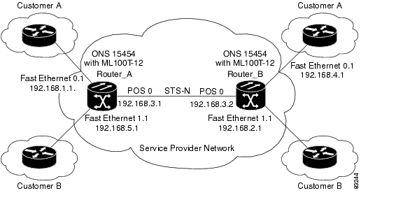
Figure 13-1 shows an example of a VRF Lite configuration. The configurations for Router A and Router B are provided in Example 13-2 and Example 13-3, respectively. The associated routing tables are shown in Example 13-4 through Example 13-9.
Figure 13-1 VRF Lite—Sample Network Scenario
Example 13-2 Router A Configuration
hostname Router_A!ip vrf customer_ard 1:1route-target export 1:1route-target import 1:1!ip vrf customer_brd 2:2route-target export 2:2route-target import 2:2!bridge 1 protocol ieeebridge 2 protocol ieeebridge 3 protocol ieee!!interface FastEthernet0no ip address!interface FastEthernet0.1encapsulation dot1Q 2ip vrf forwarding customer_aip address 192.168.1.1 255.255.255.0bridge-group 2!interface FastEthernet1no ip address!interface FastEthernet1.1encapsulation dot1Q 3ip vrf forwarding customer_bip address 192.168.2.1 255.255.255.0bridge-group 3!interface POS0no ip addresscrc 32no cdp enablepos flag c2 1!interface POS0.1encapsulation dot1Q 1 nativeip address 192.168.50.1 255.255.255.0bridge-group 1!interface POS0.2encapsulation dot1Q 2ip vrf forwarding customer_aip address 192.168.100.1 255.255.255.0bridge-group 2!interface POS0.3encapsulation dot1Q 3ip vrf forwarding customer_bip address 192.168.200.1 255.255.255.0bridge-group 3!router ospf 1log-adjacency-changesnetwork 192.168.50.0 0.0.0.255 area 0!router ospf 2 vrf customer_alog-adjacency-changesnetwork 192.168.1.0 0.0.0.255 area 0network 192.168.100.0 0.0.0.255 area 0!router ospf 3 vrf customer_blog-adjacency-changesnetwork 192.168.2.0 0.0.0.255 area 0network 192.168.200.0 0.0.0.255 area 0!Example 13-3 Router_B Configuration
hostname Router_B!ip vrf customer_ard 1:1route-target export 1:1route-target import 1:1!ip vrf customer_brd 2:2route-target export 2:2route-target import 2:2!bridge 1 protocol ieeebridge 2 protocol ieeebridge 3 protocol ieee!!interface FastEthernet0no ip address!interface FastEthernet0.1encapsulation dot1Q 2ip vrf forwarding customer_aip address 192.168.4.1 255.255.255.0bridge-group 2!interface FastEthernet1no ip address!interface FastEthernet1.1encapsulation dot1Q 3ip vrf forwarding customer_bip address 192.168.5.1 255.255.255.0bridge-group 3!interface POS0no ip addresscrc 32no cdp enablepos flag c2 1!interface POS0.1encapsulation dot1Q 1 nativeip address 192.168.50.2 255.255.255.0bridge-group 1!interface POS0.2encapsulation dot1Q 2ip vrf forwarding customer_aip address 192.168.100.2 255.255.255.0bridge-group 2!interface POS0.3encapsulation dot1Q 3ip vrf forwarding customer_bip address 192.168.200.2 255.255.255.0bridge-group 3!router ospf 1log-adjacency-changesnetwork 192.168.50.0 0.0.0.255 area 0!router ospf 2 vrf customer_alog-adjacency-changesnetwork 192.168.4.0 0.0.0.255 area 0network 192.168.100.0 0.0.0.255 area 0!router ospf 3 vrf customer_blog-adjacency-changesnetwork 192.168.5.0 0.0.0.255 area 0network 192.168.200.0 0.0.0.255 area 0!Example 13-4 Router_A Global Routing Table
Router_A# sh ip routeCodes: C - connected, S - static, I - IGRP, R - RIP, M - mobile, B - BGPD - EIGRP, EX - EIGRP external, O - OSPF, IA - OSPF inter areaN1 - OSPF NSSA external type 1, N2 - OSPF NSSA external type 2E1 - OSPF external type 1, E2 - OSPF external type 2, E - EGPi - IS-IS, L1 - IS-IS level-1, L2 - IS-IS level-2, ia - IS-IS inter area* - candidate default, U - per-user static route, o - ODRP - periodic downloaded static routeGateway of last resort is not setC 192.168.50.0/24 is directly connected, POS0.1Example 13-5 Router_A customer_a VRF Routing Table
Router_A# show ip route vrf customer_aCodes: C - connected, S - static, I - IGRP, R - RIP, M - mobile, B - BGPD - EIGRP, EX - EIGRP external, O - OSPF, IA - OSPF inter areaN1 - OSPF NSSA external type 1, N2 - OSPF NSSA external type 2E1 - OSPF external type 1, E2 - OSPF external type 2, E - EGPi - IS-IS, L1 - IS-IS level-1, L2 - IS-IS level-2, ia - IS-IS inter area* - candidate default, U - per-user static route, o - ODRP - periodic downloaded static routeGateway of last resort is not setO 192.168.4.0/24 [110/2] via 192.168.100.2, 00:15:35, POS0.2C 192.168.1.0/24 is directly connected, FastEthernet0.1C 192.168.100.0/24 is directly connected, POS0.2Example 13-6 Router_A customer_b VRF Routing Table
Router_A# show ip route vrf customer_bCodes: C - connected, S - static, I - IGRP, R - RIP, M - mobile, B - BGPD - EIGRP, EX - EIGRP external, O - OSPF, IA - OSPF inter areaN1 - OSPF NSSA external type 1, N2 - OSPF NSSA external type 2E1 - OSPF external type 1, E2 - OSPF external type 2, E - EGPi - IS-IS, L1 - IS-IS level-1, L2 - IS-IS level-2, ia - IS-IS inter area* - candidate default, U - per-user static route, o - ODRP - periodic downloaded static routeGateway of last resort is not setC 192.168.200.0/24 is directly connected, POS0.3O 192.168.5.0/24 [110/2] via 192.168.200.2, 00:10:32, POS0.3C 192.168.2.0/24 is directly connected, FastEthernet1.1Example 13-7 Router_B Global Routing Table
Router_B# sh ip routeCodes: C - connected, S - static, I - IGRP, R - RIP, M - mobile, B - BGPD - EIGRP, EX - EIGRP external, O - OSPF, IA - OSPF inter areaN1 - OSPF NSSA external type 1, N2 - OSPF NSSA external type 2E1 - OSPF external type 1, E2 - OSPF external type 2, E - EGPi - IS-IS, L1 - IS-IS level-1, L2 - IS-IS level-2, ia - IS-IS inter area* - candidate default, U - per-user static route, o - ODRP - periodic downloaded static routeGateway of last resort is not setC 192.168.50.0/24 is directly connected, POS0.1Example 13-8 Router_B customer_a VRF Routing Table
Router_B# sh ip route vrf customer_aCodes: C - connected, S - static, I - IGRP, R - RIP, M - mobile, B - BGPD - EIGRP, EX - EIGRP external, O - OSPF, IA - OSPF inter areaN1 - OSPF NSSA external type 1, N2 - OSPF NSSA external type 2E1 - OSPF external type 1, E2 - OSPF external type 2, E - EGPi - IS-IS, L1 - IS-IS level-1, L2 - IS-IS level-2, ia - IS-IS inter area* - candidate default, U - per-user static route, o - ODRP - periodic downloaded static routeGateway of last resort is not setC 192.168.4.0/24 is directly connected, FastEthernet0.1O 192.168.1.0/24 [110/2] via 192.168.100.1, 00:56:24, POS0.2C 192.168.100.0/24 is directly connected, POS0.2Example 13-9 Router_B customer_b VRF Routing Table
Router_B# show ip route vrf customer_bCodes: C - connected, S - static, I - IGRP, R - RIP, M - mobile, B - BGPD - EIGRP, EX - EIGRP external, O - OSPF, IA - OSPF inter areaN1 - OSPF NSSA external type 1, N2 - OSPF NSSA external type 2E1 - OSPF external type 1, E2 - OSPF external type 2, E - EGPi - IS-IS, L1 - IS-IS level-1, L2 - IS-IS level-2, ia - IS-IS inter area* - candidate default, U - per-user static route, o - ODRP - periodic downloaded static routeGateway of last resort is not setC 192.168.200.0/24 is directly connected, POS0.3C 192.168.5.0/24 is directly connected, FastEthernet1.1O 192.168.2.0/24 [110/2] via 192.168.200.1, 00:10:51, POS0.3Monitoring and Verifying VRF Lite
Table 13-1 shows the privileged EXEC commands for monitoring and verifying VRF Lite.
![]()
![]()
![]()
![]()
![]()
![]()
![]()
![]()
Posted: Tue Oct 30 11:58:50 PDT 2007
All contents are Copyright © 1992--2007 Cisco Systems, Inc. All rights reserved.
Important Notices and Privacy Statement.