|
|

Table Of Contents
Configuring Resilient Packet Ring
Configuring Point-to-Point Circuits on CTC for RPR
RPR Cisco IOS Configuration Example
Understanding RPR Link Fault Propagation
LFP Configuration Requirements
Understanding Dual RPR Interconnect
DRPRI IOS Configuration Example
Monitoring and Verifying DRPRI
Configuring Resilient Packet Ring
Note
The terms "Unidirectional Path Switched Ring" and "UPSR" may appear in Cisco literature. These terms do not refer to using Cisco ONS 15xxx products in a unidirectional path switched ring configuration. Rather, these terms, as well as "Path Protected Mesh Network" and "PPMN," refer generally to Cisco's path protection feature, which may be used in any topological network configuration. Cisco does not recommend using its path protection feature in any particular network configuration.
This chapter describes how to configure resilient packet ring (RPR) and Dual RPR Interconnect (DRPRI) for the ML-Series card.
This chapter contains the following major sections:
•
•
•
•
•
Understanding RPR
RPR is an emerging network architecture designed for metro fiber ring networks. This new MAC protocol is designed to overcome the limitations of IEEE 802.1D Spanning Tree Protocol (STP), IEEE 802.1W Rapid Spanning Tree Protocol (RSTP), and SONET/SDH in packet-based networks. RPR operates at the Layer 2 level and is compatible with Ethernet and SONET/SDH.
The ML-Series card's RPR relies on the quality of service (QoS) features of the ML-Series card for efficient bandwidth utilization with service level agreement (SLA) support. ML-Series card QoS mechanisms apply to all SONET/SDH traffic on the ML-Series card, whether passed-through, bridged, or stripped.
When an ML-Series card is configured with RPR and made part of a shared packet ring (SPR), the ML-Series card assumes it is part of a ring. If a packet is not destined for devices attached to the specific ML-Series, the ML-Series card simply continues to forward this transit traffic along the SONET/SDH circuit, relying on the circular path of the ring architecture to guarantee that the packet will eventually arrive at the destination. This eliminates the need to queue and forward the packet flowing through the nondestination ML-Series card. From a Layer 2 or Layer 3 perspective, the entire RPR looks like one shared network segment.
RPR supports operation over protected and unprotected SONET/SDH circuits. On unprotected SONET/SDH circuits, RPR provides SONET/SDH-like protection without the redundant SONET/SDH protection path. Eliminating the need for a redundant SONET/SDH path frees bandwidth for additional traffic. RPR also incorporates spatial reuse of bandwidth through a hash algorithm for east/west packet transmission. RPR utilizes the entire ring bandwidth and does not need to block ring segments like STP or RSTP.
Packet Handling Operations
The RPR protocol, using the transmitted packet's header information, allows the interfaces to quickly determine the operation that needs to be applied to the packet. An ML-Series card configured with RPR is part of the ring and has three basic packet-handling operations: bridge, pass-through, and strip. Figure 17-1 illustrates these operations. Bridging connects and passes packets between the Ethernet ports on the ML-Series and the packet-over-SONET/SDH (POS) circuit circling the ring. Pass-through lets the packets continue through the ML-Series card and along the ring, and stripping takes the packet off the ring and discards it. Because STP or RSTP is not in effect between nodes when RPR is configured, the transmitting RPR port strips its own packets after they return from circling the ring. A hash algorithm is used to determine the direction of the packet around the RPR.
Figure 17-1 RPR Packet Handling Operations
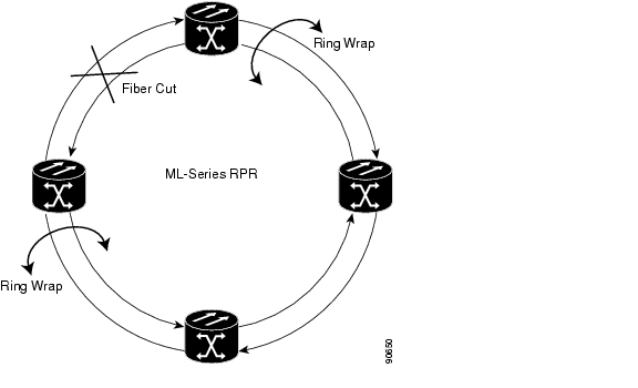
Ring Wrapping
RPR initiates ring wraps in the event of a fiber cut, node failure, node restoration, new node insertion, deletion of the circuit on POS port of SPR or other traffic problems. This protection mechanism redirects traffic to the original destination by sending it in the opposite direction around the ring after a link state change or after receiving SONET/SDH path level alarms. Ring wrapping on the ML-Series card allows convergence times of less than 50 ms. RPR convergence times are comparable to SONET/SDH and much faster than STP or RSTP.
RPR on the ML-Series card survives both unidirectional and bidirectional transmission failures within the ring. Unlike STP or RSTP, RPR restoration is scalable. Increasing the number of ML-Series cards in a ring does not increase the convergence time.
RPR wraps occur within 50 msec after the failure condition with the default spr wrap immediate configured. If spr wrap delay is configured, the wrap is delayed until the POS interface goes link-down. The link goes down after the time specified with the CLI pos trigger delay <msec>. If the circuits are VCAT then the Cico IOS CLI command pos vcat defect delayed also needs to be configured. The delay helps ensure that when RPR is configured with SONET bandwidth protection, this Layer 1 protection has a chance to take effect before the Layer 2 RPR protection. If the interface goes down without a SONET/SDH error, then the carrier delay also take effect. Figure 17-2 illustrates ring wrapping.
Figure 17-2 RPR Ring Wrapping
Note
Note
Note
MAC Address and VLAN Support
RPR improves MAC address support, because an ML-Series card does not need to learn the MAC address of pass-through packets. The ML-Series card's MAC address table only holds the MAC IDs of packets that have been bridged or stripped by that card. This allows the collective tables of the ML-Series cards in the ring to hold a greater number of MAC addresses.
RPR also enhances VLAN support relative to STP and RSTP. In an STP and RSTP, a new VLAN must configured on all POS interfaces on the ring. In RPR, the VLAN must only be added to the configuration of those interfaces that bridge or strip packets for that VLAN. The ML-Series card still has a 255 architectural maximum limit of VLAN/bridge-group per ML-Series card. But because the ML-Series card only needs to maintain the MAC address of directly connected devices per card, a greater number of connected devices are allowed on an RPR network basis.
Configuring Point-to-Point Circuits on CTC for RPR
RPR on the Cisco ONS 15454 or Cisco ONS 15454 SDH enables two or more ML-Series cards to become one functional network segment or SPR. The bridged ML-Series cards are connected to each other through point-to-point STS/STM circuits, which use one of the first ML-Series card's POS ports as a source and one of the second ML-Series card's POS ports as a destination. All ML-Series cards in an SPR must be connected directly or indirectly by point-to-point circuits.
The point-to-point circuits use the ONS 15454 SONET/SDH network. Provision the point-to-point circuits using Cisco Transport Controller (CTC) or Transaction Language One (TL1) in the same manner as an ONS 15454 OC-N card STS/STM circuits. The Cisco ONS 15454 Procedure Guide or the Cisco ONS 15454 SDH Procedure Guide provides specific instructions about how to create an automatically routed optical circuit.
When configuring a point-to-point circuit on the ML-Series:
•
•
•
After the CTC circuit process is complete, begin a Cisco IOS session to configure RPR/SPR on the ML-Series card and interfaces.
Note
Configuring RPR on Cisco IOS
You configure RPR on the ML-Series cards by creating an SPR interface from the Cisco IOS CLI. The SPR is a virtual interface, similar to an EtherChannel interface. The POS interfaces are the physical interfaces associated with the RPR SPR interface. An ML-Series card supports a single SPR interface. The SPR interface has a single MAC address and provides all the normal attributes of a Cisco IOS interface, such as support for default routes. An SPR interface is considered a trunk port, and like all trunk ports, subinterfaces must be configured for the SPR interface to become part of a bridge group.
An SPR interface is configured similarly to a EtherChannel (port-channel) interface. The members of the SPR interface must be POS interfaces. Instead of using the channel-group command to define the members, you use the spr-intf-id command. And like port-channel, you configure the SPR interfaces instead of the POS interface.
Caution
Caution
Note
To provision RPR, perform the following procedure, beginning in global configuration mode:
Caution
Caution
Each of the ML-Series card's two POS ports must be assigned to the SPR interface. To assign the POS interfaces on the ML-Series to the SPR, perform the following procedure, beginning in global configuration mode:
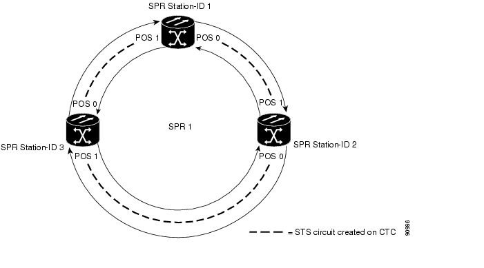
RPR Cisco IOS Configuration Example
Figure 17-3 shows an example of an RPR Cisco IOS configuration. The associated code is provided in Examples 17-1, 17-2, and 17-3. The configuration assumes that ML-Series card POS ports are already linked by point-to-point SONET/SDH circuits configured through CTC.
Figure 17-3 RPR Configuration Example
Example 17-1 SPR Station-ID 1 Configuration
bridge irb!interface SPR1no ip addressno keepalivespr station-ID 1hold-queue 150 inbridge-group 1!interface POS0no ip addressspr-intf-id 1!interface POS1no ip addressspr-intf-id 1interface Gigabit Ethernet0no ip addressno ip route-cachebridge-group 1interface Gigabit Ethernet1no ip addressno ip route-cachebridge-group 1Example 17-2 SPR Station-ID 2 Configuration
bridge irb!interface SPR1no ip addressno keepalivespr station-ID 2hold-queue 150 inbridge-group 1!interface POS0no ip addressspr-intf-id 1!interface POS1no ip addressspr-intf-id 1interface Gigabit Ethernet0no ip addressno ip route-cachebridge-group 1interface Gigabit Ethernet1no ip addressno ip route-cachebridge-group 1Example 17-3 SPR Station-ID 3 Configuration
bridge irb!interface SPR1no ip addressno keepalivespr station-ID 3hold-queue 150 inbridge-group 1!interface POS0no ip addressspr-intf-id 1!interface POS1no ip addressspr-intf-id 1interface Gigabit Ethernet0no ip addressno ip route-cachebridge-group 1interface Gigabit Ethernet1no ip addressno ip route-cachebridge-group 1Monitoring and Verifying RPR
After RPR is configured, you can monitor its status using the show interface spr or show run interface spr command ( Example 17-4).
Example 17-4 Monitor and Verify RPR
Router# show interfaces spr 1SPR1 is up, line protocol is upHardware is POS-SPR, address is 0005.9a39.714a (bia 0000.0000.0000)MTU 1500 bytes, BW 1244160 Kbit, DLY 100 usec,reliability 255/255, txload 1/255, rxload 1/255Encapsulation ONS15454-G1000, loopback not setKeepalive not setDTR is pulsed for 33391 seconds on resetARP type: ARPA, ARP Timeout 04:00:00No. of active members in this SPR interface: 2Member 0 : POS0Member 1 : POS1Last input never, output never, output hang neverLast clearing of "show interface" counters neverInput queue: 0/150/0/0 (size/max/drops/flushes); Total output drops: 0Queueing strategy: fifoOutput queue: 0/80 (size/max)5 minute input rate 1000 bits/sec, 2 packets/sec5 minute output rate 2000 bits/sec, 4 packets/sec1014 packets input, 96950 bytesReceived 0 broadcasts (0 IP multicast)0 runts, 0 giants, 0 throttles0 parity0 input errors, 0 CRC, 0 frame, 0 overrun, 0 ignored0 input packets with dribble condition detected1640 packets output, 158832 bytes, 0 underruns0 output errors, 0 applique, 9 interface resets0 babbles, 0 late collision, 0 deferred0 lost carrier, 0 no carrier0 output buffer failures, 0 output buffers swapped out0 carrier transitionsUnderstanding RPR Link Fault Propagation
Link fault propagation (LFP), also known as link pass through, decreases convergence times in networks where routers interconnect through ML-Series card RPR. It quickly relays link faults from a master Gigabit Ethernet link to a remote slave link, either Gigabit Ethernet or FastEthernet. LFP greatly improves the time it takes for a router connected to the slave link to fail over to an alternate path. Under normal protection schemes, convergence might take as long as forty seconds. Using LFP, the slave interface reflects the state of the master interface in well under a second. This feature is often used to enable a link failure at a far-end hub site to trigger a link down state at a near-end access site. Figure 17-4 illustrates LFP.
Figure 17-4 RPR Link Fault Propagation Example
LFP updates are done through a CDP packet extension. The update is sent periodically and immediately after the master interface goes into link-down. LFP updates are sent separately from normal CDP packets, and the two types do not interact. Configuring or disabling CDP on the interface has no effect on LFP updates.
When the master interface goes down, including an administrative shutdown, the slave interface is forced down. When the master interface goes up, the slave interface will go back up. Administrative shutdown on a slave interface will suspend the LFP function on that interface, and removing the shutdown will reactivate LFP.
A link-down fault is also forced onto the slave link if the connection from the master to the slave fails. Any of the following can cause a loss of conecction:
•
•
•
Link faults only propagate from master to slave. Normal slave link faults are not propagated. RPR wrapping and unwrapping has no effect on LFP.
Propagation Delays
Propagation delay includes the carrier-delay time on the slave interface. The carrier-delay time is configureable and has a default of 200 ms. See the "Configuring RPR on Cisco IOS" section for more information on configuring carrier-delay time.
Different propagation delays apply to different LFP scenarios:
•
•
•
Configuring LFP
Figure 17-4 illustrates an example of RPR configured with LFP. The process of configuring LFP consists of the following tasks:
1.
2.
To enable and configure the LFP master link, perform the following procedure, beginning in global configuration mode:
To enable and configure the LFP slave link, perform the following procedure on an ML-Series card in the RPR other than the ML-Series card configured for the master link. Begin in global configuration mode:
LFP Configuration Requirements
LFP has these configuration requirement:
•
•
•
•
•
•
•
•
Monitoring and Verifying LFP
A slave interface in link-down state raises a CARLOSS alarm on CTC. CTC does not distinguish between a local loss on the slave link and loss due to LFP. For more information on CARLOSS, refer to refer to the "Alarm Troubleshooting" chapter of the Cisco ONS 15454 Troubleshooting Guide or the "Alarm Troubleshooting" chapter of the Cisco ONS 15454 SDH Troubleshooting Guide.
The Cisco IOS status of link-down interface is shown as protocol down/link down. Neither the show controller or show interface command reveals the difference between a local loss on the link and an LFP loss.
After LFP is configured, you can monitor the LFP status of each master or slave link using the show link-fault command. Use this command to determine whether LFP caused the link down on a slave interface. Example 17-5 illustrates the output from this command on a slave interface.
Example 17-5 Monitor and Verify LFP
Router# show link-faultLink Fault Propagation Configuration:-------------------------------------LFP Config Mode : LFP_SLAVELFP Master State : LFP_STATUS_DOWNInterfaces configured for LFP:FastEthernet0 (down)Understanding Dual RPR Interconnect
Cisco ML-Series RPR includes a mechanism to interconnect rings for protection from node failure. The bridge-group protocol, DRPRI, provides two parallel connections of the rings linked by a special instance of RSTP. One connection is the active node and the other is the standby node. During a failure of the active node, link, or card, a proprietary algorithm detects the failure and causes a switchover to the standby node. DRPRI provides a recovery time of less than 200 ms for Layer 2 bridged traffic, when the ML-Series employs the enhanced microcode image. When the ML-Series employs the base or Multiprotocol Label Switching (MPLS) microcode images, the recovery time for Layer 2 bridged traffic is up to 12 seconds. With any microcode image the recovery time for Layer 3 unicast and multicast traffic also depends on the convergence time of the routing protocol implemented.
The paired ML1000-2 cards share the same station ID and are viewed by other members of the RPR as a single card. In Figure 17-5, paired cards A and B have the same SPR station ID, and paired cards C and D have the same station ID. The interconnected nodes do not need to be adjacent on the RPR. Bridging, IP routing, policing and bandwidth allocations can still be provisioned on DRPRI ML1000-2 cards.
Figure 17-5 Dual RPR Interconnect Network and Paired Cards
DRPRI has these characteristics:
•
•
•
•
•
•
•
•
•
•
•
•
•
Configuring DRPRI
DRPRI requires two pairs of ML-Series cards with one pair configured as RPR and belonging to the first of two adjacent RPRs, and the second pair configured as RPR and belonging to the second RPR ( Figure 17-5). DRPRI is configured on each of the four ML1000-2 cards that connect the two adjacent RPRs. The process of configuring DRPRI consists of the following tasks:
1.
2.
a.
b.
3.
4.
5.
To enable and configure DRPRI, perform the following procedure, beginning in global configuration mode:
Step 1
Router(config)# bridge crbConcurrent routing and bridging is enabled. When concurrent routing and bridging has been enabled, the default behavior is to bridge all protocols that are not explicitly routed in a bridge group.
Step 2
Router(config)# bridge bridge-group-number protocol drpri-rstpCreates the bridge-group number shared by the four ML1000-2 cards and assigns the protocol for DRPRI to the bridge-group. The same command using the same bridge group number must be given on each of the four cards.
Step 3
Router(config)# interface spr 1Creates the SPR interface for RPR or enters the SPR interface configuration mode on a previously created SPR interface. The only valid SPR number is 1.
Step 4
Router(config-if)# spr station-ID station-ID-numberConfigures a station identification number. The user must configure the same station ID on both the paired cards. Valid station ID numbers range from 1 to 254.
Step 5
Router(config-if)# spr drpri-ID {0 | 1}Creates a DRPRI identification number of 0 or 1 to differentiate between the ML1000-2 cards paired for DRPRI.
Step 6
Router(config-if)# interface spr shared-packet-ring-subinterface-numberCreates the SPR subinterface.
Step 7
Router(config-subif)# encapsulation dot1q vlan-IDSets the SPR subinterface encapsulation to IEEE 802.1Q.
Step 8
Router(config-subif)# bridge-group bridge-group-numberAssigns the SPR subinterface to a bridge-group.
Step 9
Router(config)# interface port-channel channel-numberCreates the GEC interface or channel-group.
Step 10
Router(config-if)# interface Gigabit Ethernet numberEnters interface configuration mode for the first Gigabit Ethernet interface that you want to assign to the GEC subinterface.
Step 11
Router(config-if)# channel-group channel-numberAssigns the Gigabit Ethernet interfaces to the GEC. The channel number must be the same channel number that you assigned to the EtherChannel interface.
Step 12
Router(config-if)# interface Gigabit Ethernet numberEnters interface configuration mode for the second Gigabit Ethernet interface that you want to assign to the GEC subinterface.
Step 13
Router(config-if)# channel-group channel-numberAssigns the Gigabit Ethernet interfaces to the GEC. The channel number must be the same channel number that you assigned to the EtherChannel interface.
Step 14
Router(config-subif)# interface port-channel channel-sub-interface-numberCreates the GEC subinterface.
Step 15
Router(config-subif)# encapsulation dot1q vlan-IDSets subinterface encapsulation to IEEE 802.1Q. The VLAN ID used should be the same VLAN ID used in Step 7.
Step 16
Router(config-subif)# bridge-group bridge-group-numberAssigns the GEC subinterface to the bridge-group.
Step 17
Router(config-if)# endExits to privileged EXEC mode.
Step 18
Router# copy running-config
startup-config
(Optional) Saves configuration changes to NVRAM.
DRPRI IOS Configuration Example
Figure 17-5 shows an example of RPR configuration. The associated code is provided in Examples 17-6, 17-7, 17-8, and 17-9.
Example 17-6 ML-Series Card A Configuration
hostname ML-Series Abridge crbbridge 100 protocol drpri-rstpinterface Port-channel1no ip addressno ip route-cachehold-queue 300 ininterface Port-channel1.1encapsulation dot1Q 10no ip route-cachebridge-group 100interface SPR1no ip addressno keepalivespr station-ID 1hold-queue 150 ininterface SPR1.1encapsulation dot1Q 10bridge-group 100interface Gigabit Ethernet0no ip addressno ip route-cachechannel-group 1interface Gigabit Ethernet1no ip addressno ip route-cachechannel-group 1interface POS0no ip addressspr-intf-id 1crc 32interface POS1no ip addressspr-intf-id 1crc 32ip classlessno ip http serverExample 17-7 ML-Series Card B Configuration
hostname ML-Series Bbridge crbbridge 100 protocol drpri-rstpinterface Port-channel1no ip addressno ip route-cachehold-queue 300 ininterface Port-channel1.1encapsulation dot1Q 10no ip route-cachebridge-group 100interface SPR1no ip addressno keepalivespr station-ID 1spr drpr-ID 1hold-queue 150 ininterface SPR1.1encapsulation dot1Q 10bridge-group 100interface Gigabit Ethernet0no ip addressno ip route-cachechannel-group 1interface Gigabit Ethernet1no ip addressno ip route-cachechannel-group 1interface POS0no ip addressspr-intf-id 1crc 32interface POS1no ip addressspr-intf-id 1crc 32ip classlessno ip http serverExample 17-8 ML-Series Card C Configuration
hostname ML-Series Cbridge crbbridge 100 protocol drpri-rstpinterface Port-channel1no ip addressno ip route-cachehold-queue 300 ininterface Port-channel1.1encapsulation dot1Q 10no ip route-cachebridge-group 100interface SPR1no ip addressno keepalivespr station-ID 2hold-queue 150 ininterface SPR1.1encapsulation dot1Q 10bridge-group 100interface Gigabit Ethernet0no ip addressno ip route-cachechannel-group 1interface Gigabit Ethernet1no ip addressno ip route-cachechannel-group 1interface POS0no ip addressspr-intf-id 1crc 32interface POS1no ip addressspr-intf-id 1crc 32ip classlessno ip http serverExample 17-9 ML-Series Card D Configuration
hostname ML-Series Dbridge crbbridge 100 protocol drpri-rstpinterface Port-channel1no ip addressno ip route-cachehold-queue 300 ininterface Port-channel1.1encapsulation dot1Q 10no ip route-cachebridge-group 100interface SPR1no ip addressno keepalivespr station-ID 2spr drpr-ID 1hold-queue 150 ininterface SPR1.1encapsulation dot1Q 10bridge-group 100interface Gigabit Ethernet0no ip addressno ip route-cachechannel-group 1interface Gigabit Ethernet1no ip addressno ip route-cachechannel-group 1interface POS0no ip addressspr-intf-id 1crc 32interface POS1no ip addressspr-intf-id 1crc 32ip classlessno ip http serverMonitoring and Verifying DRPRI
After DRPRI is configured, you can monitor its status using the show bridge verbose command ( Example 17-10).
Example 17-10 show bridge verbose Command
Router# show bridge bridge-group-number verbose
![]()
![]()
![]()
![]()
![]()
![]()
![]()
![]()
Posted: Tue Oct 30 11:53:05 PDT 2007
All contents are Copyright © 1992--2007 Cisco Systems, Inc. All rights reserved.
Important Notices and Privacy Statement.