|
|

Product Number MC-CCTL-V3.0=
This publication describes how to upgrade the erasable programmable read-only memory (EPROM) components on the first-generation (Hardware Revision 3.0) ciscoBus controller card (CSC-CCTL) from Microcode Version 1.0 or 2.0 to Microcode Version 3.0. To upgrade the CSC-CCTL card, you must replace nine EPROM components, which are shipped in the microcode upgrade kit designated MC-CCTL-V3.0=. The ciscoBus controller card is marked "Rev./3" for the CSC-CCTL card
type 3.0.
To confirm the microcode upgrade requirements for your CSC-CCTL cards, use the EXEC command show controller cbus. The first line of the command display contains the controller card type and microcode version.
Execute the show controller cbus command on the installed CSC-CCTL type 3.0 card. Following is part of the information displayed:
cBus 0, controller type 3.0, microcode version 2.0 (or 1.0)
Verify that the ciscoBus controller is type 3.0 (Rev./ 3) and that the microcode version is 1.0 or 2.0 for the CSC-CCTL card.
All ciscoBus interface cards contain card-specific microcode that determines whether the card is compatible with the first- or second-generation ciscoBus controller card. Only ciscoBus cards with microcode versions earlier than Version 10.0 are compatible with the first-generation ciscoBus controller card (CSC-CCTL). All ciscoBus cards with the prefix C2 (and by default, Microcode Version 10.0 or later) must be used with the second-generation ciscoBus controller card (CSC-CCTL2).
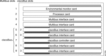
The CSC-CCTL ciscoBus controller card is located in the center ciscoBus slot (Multibus slot 7) in the AGS+ chassis card cage. (See Figure 1.)

Follow these guidelines when working with any electrical equipment:
In addition, use the following guidelines when working with any equipment that is connected to telephone wiring or other network cabling.
Electrostatic discharge (ESD) is a discharge of stored static electricity that can damage equipment and impair electrical circuitry. It occurs when electronic components are improperly handled and can result in complete or intermittent failures.
Following are guidelines for preventing ESD damage:
 | Caution For safety, periodically check the resistance value of the antistatic strap. The measurement should be within the range of 1 and 10 Mohms. |
Following are the procedures required to open the AGS+ chassis, remove the CSC-CCTL card, and upgrade the microcode EPROMs.
You need some or all of the following tools and parts to perform the upgrade procedure. Before you begin, read through the procedure to determine which tools you need for your chassis.
Following is the procedure for accessing the chassis interior.
Step 1 If you will need to handle any electronic components (cards, and so forth), attach appropriate ESD protection and attach the AC power cord, but to prevent a shock hazard, make certain the chassis power is OFF.
Step 2 To access cards in the card cage, loosen the two thumbscrews and remove the front panel from the chassis. (See Figure 2.)
The front panel is secured with two thumbscrews, which are tightened with 12 in/lb of torque for shipping. If you are removing the front panel for the first time, use the medium flat-blade screwdriver to turn the thumbscrews counterclockwise to loosen. When you replace the panel, turn the thumbscrews clockwise until finger-tight.

Following is the procedure for upgrading the nine microcode EPROMs on the type 3.0 CSC-CCTL card:
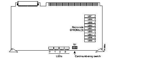
Step 1 Remove the CSC-CCTL card from the card cage, and position it as shown in Figure 3. It may be necessary to first disconnect interface cables that are blocking the CSC-CCTL card. Note their position for reassembly.

Step 2 Remove the Version 1.0 or Version 2.0 EPROM components (listed in Table 1 under the heading "Old Part Numbers") by gently lifting each from its socket using the EPROM extraction tool or the small flat-blade screwdriver.
| Old Part Numbers | New Part Numbers | ||
|---|---|---|---|
| Socket | Microcode Version 1.0 | Microcode Version 2.0 | Microcode Version 3.0 |
| U207 | A6-V1.0 17-0714V1.0 | 17-0714-01 U207 | 17-0714-02 U207 |
| U206 | A5-V1.0 17-0713V1.0 | 17-0713-01 U206 | 17-0713-02 U206 |
| U205 | A4-V1.0 17-0712V1.0 | 17-0712-01 U205 | 17-0712-02 U205 |
| U202 | A1-V1.0 17-0709V1.0 | 17-0709-01 U202 | 17-0709-02 U202 |
| U201 | A0-V1.0 17-0708V1.0 | 17-0708-01 U201 | 17-0708-02 U201 |
| U203 | A2-V1.0 17-0710V1.0 | 17-0710-01 U203 | 17-0710-02 U203 |
| U204 | A3-V1.0 17-0711V1.0 | 17-0711-01 U204 | 17-0711-02 U204 |
| U208 | A7-V1.0 17-0715V1.0 | 17-0715-01 U208 | 17-0715-02 U208 |
| U209 | A8-V1.0 17-0716V1.0 | 17-0716-01 U209 | 17-0716-02 U209 |
Step 3 Replace the old components with the Version 3.0 components listed in Table 1 under the heading "New Part Numbers." Make sure the notched end of each new EPROM has the same orientation as the EPROM you removed; align the notch in the EPROM with the notch in the socket. Do not use the orientation of the label to align each new EPROM.
Step 4 When all nine EPROMs are installed, check the pins and the EPROM orientation in the sockets. Straighten or realign any problematic pins or EPROMs.
 | Caution If a microcode EPROM is installed backwards when the power is turned on, it will be damaged and will have to be replaced. If any of the EPROM pins are bent during installation, the ciscoBus controller card might not operate properly. If this happens, remove the EPROM, use needlenose pliers to straighten any bent pins, then reinsert it and try again. If a pin breaks off, the component will have to be replaced. |
Step 5 Install the CSC-CCTL card in the card cage and reattach any interface cables you removed earlier, but do not reattach the chassis access panel.
This completes the microcode upgrade procedure. Proceed to the section "Checking the Upgrade."
Figure 4 illustrates the LEDs that are on when a card is present in a corresponding ciscoBus slot. (The orientation of Figure 4 is looking at the front edge of the card installed in the card cage.) The numbers above each LED indicate the ciscoBus slot number. Depending on the slot in which the ciscoBus card is installed (slot 0 through 3), the corresponding LED will be on to indicate a card in that slot. Some ciscoBus cards have appliques that require power from the card to which they attach. If these appliques are not connected correctly, the corresponding LED on the CSC-CCTL will be off. All other LEDs are momentarily on at power up, but are not currently used.

Step 1 Turn ON the chassis power and boot the system.
Step 2 Verify the microcode upgrade by executing the EXEC command show controller cbus. The first line of the command display contains the controller card type and microcode version. Following is part of the information displayed:
Step 3 Verify that the microcode version is Version 3.0 for the type 3.0 CSC-CCTL card.
Step 4 Check the four LEDs on the CSC-CCTL. (See Figure 4.) Ensure that each LED is on for each ciscoBus slot occupied by a ciscoBus card; the ciscoBus controller LEDs are off for ciscoBus slots that contain Multibus cards. If any LEDs are not on that should be, do the following:
Step 5 When the upgrade checks out, reattach the chassis access panel.
This completes Upgrading CSC-CCTL Cards from Microcode Version 1.0 or 2.0 to Version 3.0.
Cisco Systems' Customer Information Online (CIO) system provides online information and electronic services to Cisco direct customers and business partners. Basic CIO services include general Cisco information, product announcements, descriptions of service offerings, and download access to public and authorized files, including release notes and software. Maintenance customers receive a much broader offering, including technical notes, the bug database, and electronic mail access to the TAC. (Maintenance customers must have authorization from their Cisco contract administrators to receive these privileges.)
For dialup or Internet users, CIO supports Zmodem, Kermit, Xmodem, FTP PUT, Internet e-mail, Telnet, rlogin, and fax download options. Internet users also can retrieve files from CIO using FTP.
Registration for CIO is handled on line. To reach CIO via the Internet, use Telnet or FTP to cio.cisco.com (131.108.89.33). To reach CIO by dialup, use 415 903-8070 (Mountain View, California) or 33 1 6446 4082 (Paris, France).


|
|