|
|

Product Number MC-1R/2R-V1.6=
The CSC-1R and CSC-2R cards use an erasable programmable read-only memory (EPROM) device that holds the microcode (firmware) for the card. As the features of these cards increase, this EPROM may need to be upgraded. The procedures in this document are necessary if the EPROM on the STR card must be upgraded or replaced. In this document, both cards are referred to as the STR card.
At a minimum, the STR card requires that System Software Release 9.0 or later be installed on the processor card. For Microcode Version 1.6, Software Releases 9.0(4), 9.1(2), or later are required.
Electrostatic discharge damage (ESD) occurs when electronic printed circuit cards are improperly handled and can result in complete or intermittent failures. ESD can impair electronic circuitry and equipment. Always follow ESD prevention procedures when removing and replacing cards. Following are steps for handling printed circuit cards:
Step 1 Slip on an ESD-preventive wrist strap, ensuring that it makes good skin contact.
Step 2 Connect the strap to an unpainted chassis frame surface or another proper grounding point or surface to safely channel unwanted ESD voltages to ground.
Step 3 Use the ejectors to remove the card. Handle the card by its sides. Place the card on an antistatic surface or in a static shielding bag. To prevent further damage to the card by ESD voltages, defective cards must remain in the static shielding bag when returned for repair or replacement.
Step 4 Handling the new card by its edges only, insert it into the chassis. Avoid contact between the card and clothing. The wrist strap only protects the card from ESD voltages on the body; ESD voltages on clothing can still damage the card.
 | Caution Use an ohmmeter to check the ESD-preventive wrist strap to ensure that the resistor is providing proper ESD protection. For safety, the measurement should be in the range 1 to 10 megohm (Mohm). |
Following are the procedures for replacing the EPROM on the STR card. Choose the chassis-access procedure that applies to your chassis type (AGS+, M, or C chassis).
Following is a list of tools, materials, and parts needed to perform this procedure:
Following is the procedure for accessing the AGS+ chassis interior.
 | Warning Before accessing the chassis interior and removing any cards, turn off power to prevent electrical shock hazard. Attach appropriate ESD protection before beginning this procedure. |
Step 1 Turn OFF power to the chassis, but to channel ESD voltages to ground, do not unplug it.
Step 2 Remove the chassis' front access panel and set it aside (see Figure 1).

Step 3 Proceed to the section "EPROM Replacement."
Following is the procedure for accessing the M chassis interior.
 Before accessing the chassis interior and removing any cards, turn off power to prevent electrical shock hazard. Attach appropriate ESD protection before beginning this procedure. Before accessing the chassis interior and removing any cards, turn off power to prevent electrical shock hazard. Attach appropriate ESD protection before beginning this procedure. |
Step 1 Turn OFF power to the chassis, but to channel ESD voltages to ground, do not unplug it.
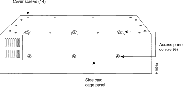
Step 2 Locate the three slotted screws that secure the top of the card cage access panel. Use the flat-blade screwdriver to turn each of these screws 1/4 to 1/2 turn counterclockwise until the screws pop up. (See Figure 2.)
Step 3 Loosen the three Phillips screws at the bottom edge of the card cage access panel (do not remove these screws completely).

Step 4 Carefully remove the access panel and set it aside.
Step 5 Proceed to the section "EPROM Replacement."
Following is the procedure for accessing the C chassis.
 Before accessing the chassis interior and removing any cards, turn off power to prevent electrical shock hazard. Attach appropriate ESD protection before beginning this procedure. Before accessing the chassis interior and removing any cards, turn off power to prevent electrical shock hazard. Attach appropriate ESD protection before beginning this procedure. |
Step 1 Turn OFF power to the chassis, but to channel ESD voltages to ground, do not unplug it.
Step 2 Use the Number 2 Phillips screwdriver to remove the ten screws that secure the cover of the
C chassis. There are two screws on each side and six screws on the bottom of the chassis. (See Figure 3.)
Step 3 Orient the chassis so that the back (the side with the ports) is on your left, the front of the chassis (which has the LED) is on your right, and the top of the chassis is facing up. This will place the power supply on the side of the chassis closest to you after you remove the cover.
Step 4 Pull the front of the cover to the right while securing the back of the chassis with your left hand. Pull slowly and carefully; the fit is snug.

 | Caution Several cables are located close to the interior of the C chassis cover. Avoid damage to these cables by ensuring that they do not impede the cover as you remove it. |
Step 5 Pull the cover to the right until the power supply and the card cage are completely exposed, but do not pull the cover completely off.
Step 6 Proceed to the section "EPROM Replacement."
Following is the procedure for replacing the EPROM on the STR card:
Step 1 Attach appropriate ESD protection.
Step 1 Disconnect and label any adjacent cables that will impede removal of the STR card.
Step 2 Disconnect the flat cable (if one is present) attached to the 50-pin connector.
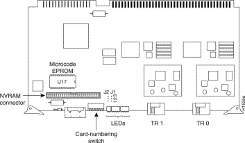
Step 3 Disconnect the Token Ring cable(s) attached to the STR card and remove the card; place it on an antistatic mat or antistatic foam. Orient the card as shown in Figure 4 (the CSC-2R card is shown--the EPROM on the CSC-1R is in the same location on the card).
Step 4 Referring to Figure 4, locate the EPROM (socket location U17) on the right side of the card, just below the 50-pin connector.
Step 5 Note the orientation of the notch on the left end of the EPROM to aid in inserting the new EPROM. Do not rely on the orientation of the label on the new EPROM for correct positioning.
Step 6 Use an EPROM removal tool, chip removal tool, or a small flat-blade screwdriver to gently remove the EPROM.
Step 7 Install the new EPROM, observing the correct notch orientation. Do not bend or break any of the pins. To straighten a bent pin, use needle nose pliers. If a pin breaks or if the EPROM was installed backwards when power is turned on, the EPROM is unusable. Contact a service representative for a replacement.

Step 8 Reinsert the STR card in its card cage slot and reattach all removed cables.
Step 9 Reattach the cables removed in steps 1-3. Do not reassemble the chassis at this time. If you need to return to the old version of STRMON microcode, use the empty box from the new EPROM to save the old EPROM.
Step 10 Proceed to the section "Testing the Upgrade."
Following is the procedure for testing the upgrade:
Step 1 Plug in the power cord and turn ON the power to the chassis for an installation check.
Step 2 Verify that the system boots correctly and that all Token Ring interfaces are shown in the boot screen.
Step 3 Use the show controller token command to verify that you have the correct microcode version on the STR card. Following is sample output of this command on an STR card with Microcode Version 1.6. In the following sample output, f/w ver means the microcode version.
Step 4 After verifying the correct microcode version, replace the card access panel and top cover (if removed) on the A+, A, M, or C chassis. Make certain to attach the card clips on the
C chassis.
This completes Upgrading the Microcode EPROM on the CSC-1R and CSC-2R Token Ring Interface Cards.
The system is now ready to reinstall in the network.


|
|