|
|

Table Of Contents
Basic Configuration:
Configuring Global and Interface AttributesConfiguring Quality of Service
Configuring Marking and Classification
Configuring DSCP-to-CoS Mapping
Configuring CoS-to-Queue Mapping
Configuring Network Enhancements
Configuring Hardware Rate Limiters
Configuring Non-Solution-Specific Features
Implementing the Solution
This chapter presents the following major topics:
•
Basic Configuration: Configuring Global and Interface Attributes
•
•
•
•
Network Topology
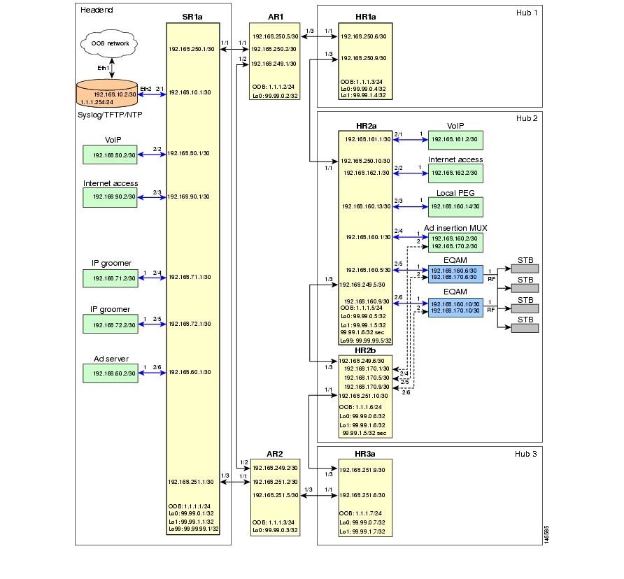
Figure 3-1 illustrates the network topology that was tested. (See Hub and IP Architecture.)
Figure 3-1 Network Topology
Basic Configuration:
Configuring Global and Interface AttributesThe following tasks are presented:
Configuring Routing
End-to-end network connectivity is accomplished by using multiple dynamic protocols and processes. OSPF is used to advertise the transport links, interswitch links, and loopbacks, while internal BGP (iBGP) is used to advertise subnets for the edge devices.
Note
OSPF is configured into two domains, one for the RAN and one for the hub. The RAN OSPF process enables connectivity and shortest path through the network; the hub OSPF process enables connectivity within the hub. The two domains simplify the routing tables on the RAN and hub routers, because a hub does not have routes for the interhub links of the other hubs. Routing table stability is also improved, because network changes in a hub are not advertised out of the hub.
The iBGP uses route reflectors and route reflector clients to advertise the subnets for the edge devices throughout the network. The SR and HR routers advertise their hub OSPF and directly connected subnets up to the AR routers, which aggregate all the received routes and advertise the aggregate back to the SR and HR routers.
To configure routing, perform the following tasks:
•
•
•
Configuring the RAN OSPF Process
The RAN OSPF routing configurations on SR, AR, and HR routers are similar. To configure HR2a, do the following.
Step 1
router ospf 100router-id 99.99.0.5Step 2
log-adjacency-changes detailmaximum-paths 6Step 3
passive-interface defaultno passive-interface TenGigabitEthernet1/1no passive-interface TenGigabitEthernet1/3network 99.99.0.0 0.0.255.255 area 0network 192.168.249.0 0.0.0.255 area 0network 192.168.250.0 0.0.0.255 area 0Step 4
timers throttle spf 400 400 4000•
•
•
Step 5
max-metric router-lsa on-startup wait-for-bgpConfiguring the Hub OSPF Process
In the testing of this solution, no devices in the hubs other than the HR routers participated in OSPF, so the configurations do not contain a configuration for this process. However, it is described here for completeness.
Step 1
Configure the hub OSPF process, noting the variables in
<angle brackets>.router ospf 200router-id 99.99.1.5log-adjacency-changesmaximum-paths 6passive-interface defaultno passive-interface GigabitEthernet2/48network <hub point-to-point link> 0.0.0.3 area 1network <IP address of attached routing device> <wildcard mask> area 1timers throttle spf 400 400 4000max-metric router-lsa on-startup wait-for-bgpdistance ospf external 175Step 2
a.
ip prefix-list hub-ospf-to-bgp-pfx seq 100 permit <hub point-to-point link>/30 le 32ip prefix-list hub-ospf-to-bgp-pfx seq 200 permit <IP address of attached routing device>/<subnet mask> le <bitmask>b.
route-map hub-ospf-to-bgp permit 100match ip address prefix-list hub-ospf-to-bgp-pfxset metric 100set ip next-hop <hub loopback1 primary address>
Note
Configuring the iBGP Process
The iBGP routing configuration on the SR and HR routers is similar. To configure HR2a, do the following.
Step 1
router bgp 100bgp router-id 99.99.0.5Step 2
no synchronizationno auto-summaryStep 3
bgp log-neighbor-changesStep 4
ip bgp-community new-format
Note
http://www.faqs.org/rfcs/rfc1997.htmlStep 5
neighbor rr-server peer-groupneighbor rr-server remote-as 100neighbor rr-server update-source Loopback0neighbor rr-server version 4neighbor rr-server send-communityStep 6
neighbor 99.99.0.2 peer-group rr-serverneighbor 99.99.0.2 description AR1neighbor 99.99.0.3 peer-group rr-serverneighbor 99.99.0.3 description AR2Step 7
redistribute connected route-map rmap_Connected-to-BGPStep 8
redistribute ospf 200 route-map hub-ospf-to-bgp
Step 9
a.
ip prefix-list pl_Connected-to-BGP seq 5 permit 192.168.160.0/24 le 32b.
route-map rmap_Connected-to-BGP permit 100match ip address prefix-list pl_Connected-to-BGPset metric 100set ip next-hop 99.99.0.5The BGP configuration on the AR routers is similar. To configure AR1, do the following.
Step 1
router bgp 100bgp router-id 99.99.0.2Step 2
•
•
no synchronizationno auto-summaryStep 3
bgp log-neighbor-changesStep 4
ip bgp-community new-formatStep 5
neighbor rr-client peer-groupneighbor rr-client remote-as 100neighbor rr-client update-source Loopback0neighbor rr-client version 4neighbor rr-client route-reflector-clientneighbor rr-client send-communityStep 6
neighbor 99.99.0.1 peer-group rr-clientneighbor 99.99.0.1 description SR1aneighbor 99.99.0.4 peer-group rr-clientneighbor 99.99.0.4 description HR1aneighbor 99.99.0.5 peer-group rr-clientneighbor 99.99.0.5 description HR2aneighbor 99.99.0.6 peer-group rr-clientneighbor 99.99.0.6 description HR2bneighbor 99.99.0.7 peer-group rr-clientneighbor 99.99.0.7 description HR3aStep 7
neighbor ibgp peer-groupneighbor ibgp remote-as 100neighbor ibgp update-source Loopback0neighbor ibgp version 4neighbor ibgp send-communityStep 8
neighbor 99.99.0.3 peer-group ibgpneighbor 99.99.0.3 description AR2Step 9
network 192.168.10.0 route-map rmap_Network-Managementnetwork 192.168.60.0 route-map rmap_Ad-Insertionnetwork 192.168.71.0 route-map rmap_IPmc-DS-Sourcenetwork 192.168.72.0 route-map rmap_IPmc-DB-Sourcenetwork 192.168.80.0 route-map rmap_Voicenetwork 192.168.90.0 route-map rmap_Internet-Accessnetwork 192.168.150.0 route-map rmap_Hub1network 192.168.160.0 route-map rmap_Hub2network 192.168.170.0 route-map rmap_Hub2network 192.168.180.0 route-map rmap_Hub3Step 10
route-map rmap_Network-Management permit 100set metric 100route-map rmap_Ad-Insertion permit 100set metric 100route-map rmap_IPmc-DS-Source permit 100set metric 100route-map rmap_IPmc-DB-Source permit 100set metric 100route-map rmap_Voice permit 100set metric 100route-map rmap_Internet-Access permit 100set metric 100route-map rmap_Hub1 permit 100set metric 100route-map rmap_Hub2 permit 100set metric 100route-map rmap_Hub3 permit 100set metric 100Configuring Multicast
Video equipment currently supports IGMPv2 and is starting to support IGMPv3. Cisco has a transitional solution to help customers implement SSM with IGMPv2 instead of waiting for multicast clients to support IGMPv3. IGMPv2 Membership Reports are converted to IGMPv3 on the Cisco router, which uses static mappings or a DNS server to resolve the source address of the multicast group. The static mappings and DNS server implementations both have pros and cons, which the user needs to weigh before implementing either approach.
Note
In this solution, static SSM mappings are used. This requires the user to map all multicast groups to the appropriate source addresses for SSM multicast to operate properly. The following SSM configuration is implemented on all switches in the network.
Note
The following tasks are presented below:
Configuring SSM
To configure SSM, do the following.
Step 1
ip multicast routingStep 2
ip igmp ssm-map enable
Note
Step 3
no ip igmp ssm-map query dnsStep 4
a.
ip access-list standard acl_SSM-IPmc-rangepermit 239.0.0.0 0.255.255.255b.
ip pim ssm range acl_SSM-IPmc-range
Tip
Step 5
ip access-list standard acl_SSM-map-DBremark SSM mapping for DB blue/redpermit 239.16.0.0 0.0.0.255ip access-list standard acl_SSM-map-DSremark SSM mapping for DS blue/redpermit 239.20.0.0 0.0.255.255ip access-list standard acl_SSM-map-DS-post-spliceremark SSM mapping for post splice DS blue/redpermit 239.28.0.0 0.0.255.255ip igmp ssm-map static acl_SSM-map-DB 192.168.71.2ip igmp ssm-map static acl_SSM-map-DS 192.168.72.2ip igmp ssm-map static acl_SSM-map-DS-post-splice 192.168.160.2Step 6
HR2a# show ip igmp ssm-mappingSSM Mapping : EnabledDNS Lookup : DisabledMcast domain : in-addr.arpaName servers : 255.255.255.255HR2a# show ip igmp ssm-mapping 239.16.0.1Group address: 239.16.0.1Database : StaticSource list : 192.168.71.2
Note
http://www.cisco.com/univercd/cc/td/doc/product/software/ios123/123newft/123t/123t_2/gtssmma.htmConfiguring IGMP
The configuration of IGMP depends on the version of IGMP that is configured for the attached IGMP clients. The two options are discussed below.
•
•
Note
All Clients Support IGMPv2 Only
If any clients support only IGMPv2, then you should configure the router interfaces connected to the IGMP client for IGMPv2, which is the default. (To restore the default, use the ip igmp version 2 command in global configuration mode.)
If the router receives an IGMPv2 Membership Report (MR) for a multicast group in the SSM range, the MR is accepted and converted to IGMPv3 if SSM static or DNS mapping is configured on the router. Otherwise, the IGMPv2 MR is ignored. If the router receives an IGMPv2 MR for a multicast group outside of the SSM range, then the MR is accepted and processed as Any Source Multicast (ASM). Consequently, if the router receives an IGMPv3 MR, the MR is ignored. The router later sends an IGMPv2 Membership Query, and the client should see this lower version and start using IGMPv2 MRs. The router then behaves as previously described.
All Clients Support and Are Configured for IGMPv3
If all of the clients support and are configured for IGMPv3, then you should configure the router interface for IGMPv3. To enable this, use the ip igmp version 3 command in global configuration mode.
In this case, if the router receives an IGMPv2 MR, the router ignores the MR. If the router receives an IGMPv3 MR for a multicast group in the SSM range, the MR is accepted and processed as IGMPv3. If the router receives an IGMPv3 MR for a multicast group outside the SSM range, the MR is accepted and processed as ASM.
Configuring Quality of Service
In this solution, Quality of Service (QoS) is based on Differentiated Services (DiffServ). (See QoS Fundamentals.) Traffic is marked at the ingress ports of the network, and each router in the network independently provides varying levels of quality by means of queueing and scheduling.
The traffic types in Table 2-5 have different QoS requirements. For example, VoIP traffic requires minimum loss and minimum jitter; video traffic requires no loss and low jitter; and, at the lower end, suspect traffic can suffer loss and high jitter.
The following tasks are presented below:
•
•
•
Configuring Marking and Classification
The first step in providing quality of service is to classify and mark traffic according to Table 2-5. Traffic is classified and marked at the edges, and the transports trust the DSCP value on incoming packets. To configure marking and classification, do the following.
Step 1
mls qosStep 2
Caution
ip access-list extended acl_voiceremark Identify voice trafficpermit ip any 192.168.161.0 0.0.0.255ip access-list extended acl_broadcast-videoremark Identify broadcast video traffic (multicast on 239.x.x.x)permit ip any 239.0.0.0 0.255.255.255ip access-list extended acl_ad-serverremark Identify ad server trafficpermit ip 192.168.60.0 0.0.0.255 anyip access-list extended acl_video-signalingremark Identify video signalingpermit ip any 192.168.61.0 0.0.0.255ip access-list extended acl_net-mgmtremark Identify net management traffic (TFTP, Syslog, NTP, etc)permit ip 192.168.10.0 0.0.0.255 anypermit ip any 192.168.10.0 0.0.0.255ip access-list extended acl_internet-accessremark Identify Internet access trafficpermit ip 192.168.90.0 0.0.0.255 anyip access-list extended acl_permit-anypermit ip any anyStep 3
class-map match-all class_voicematch access-group name acl_voiceclass-map match-all class_broadcast-videomatch access-group name acl_broadcast-videoclass-map match-all class_ad-servermatch access-group name acl_ad-serverclass-map match-all class_video-signalingmatch access-group name acl_video-signalingclass-map match-all class_net-mgmtmatch access-group name acl_net-mgmtclass-map match-all class_internet-accessmatch access-group name acl_internet-accessclass-map match-all class_suspectmatch access-group name acl_permit-anyStep 4
policy-map pmap_voice-portclass class_voicetrust dscpclass class_net-mgmtset dscp cs2class class_suspectset dscp defaultpolicy-map pmap_broadcast-video-portclass class_broadcast-videoset dscp af41class class_video-signalingset dscp cs3class class_net-mgmtset dscp cs2class class_suspectset dscp defaultpolicy-map pmap_ad-server-portclass class_ad-serverset dscp af41class class_video-signalingset dscp cs3class class_net-mgmtset dscp cs2class class_suspectset dscp defaultpolicy-map pmap_net-mgmt-portclass class_net-mgmtset dscp cs2class class_suspectset dscp defaultpolicy-map pmap_internet-access-portclass class_internet-accessset dscp 8class class_net-mgmtset dscp cs2class class_suspectset dscp defaultStep 5
interface GigabitEthernet2/1description Syslog/TFTP/NTP on PC0a (Eth2) dual-homed to 1.1.1.0/24ip address 192.168.10.1 255.255.255.252<---snip--->service-policy input pmap_net-mgmt-portinterface GigabitEthernet2/2description Voice over IPip address 192.168.80.1 255.255.255.252<---snip--->service-policy input pmap_voice-portinterface GigabitEthernet2/3description Internet Accessip address 192.168.90.1 255.255.255.252<---snip--->service-policy input pmap_internet-access-portinterface GigabitEthernet2/4description CherryPicker DM0a (Port 1) - DBip address 192.168.71.1 255.255.255.252<---snip--->service-policy input pmap_broadcast-video-portinterface GigabitEthernet2/5description CherryPicker DM0b (Port 1) - DSip address 192.168.72.1 255.255.255.252<---snip--->service-policy input pmap_broadcast-video-portinterface GigabitEthernet2/6description Ad Server Ad0aip address 192.168.60.1 255.255.255.252<---snip--->service-policy input pmap_ad-server-portStep 6
interface TenGigabitEthernet1/1description Transport between AR1 (TenGig1/1)ip address 192.168.250.1 255.255.255.252<---snip--->mls qos trust dscpConfiguring DSCP-to-CoS Mapping
The DSCP values are used to carry the QoS value between the switches. Once the packet is in the switch, the Class of Service (CoS) value is used to queue the packet in the transmit queues. There are 64 possible DSCP values and only 8 CoS values, so multiple services need to be mapped to a single CoS value.
To configure DSCP-to-CoS mapping, do the following:
Step 1
SR1a# show mls qos maps dscp-cosDscp-cos map: (dscp= d1d2)d1 : d2 0 1 2 3 4 5 6 7 8 9-------------------------------------0 : 00 00 00 00 00 00 00 00 01 011 : 01 01 01 01 01 01 02 02 02 022 : 02 02 02 02 03 03 03 03 03 033 : 03 03 04 04 04 04 04 04 04 044 : 05 05 05 05 05 05 05 05 06 065 : 06 06 06 06 06 06 07 07 07 076 : 07 07 07 07Step 2
mls qos map dscp-cos 34 36 38 to 6mls qos map dscp-cos 46 48 to 5mls qos map dscp-cos 26 28 30 to 4mls qos map dscp-cos 16 18 20 to 3mls qos map dscp-cos 40 42 44 to 2mls qos map dscp-cos 8 10 to 1mls qos map dscp-cos 0 2 to 0
Note
SR1a# show running-config | include mls qos mapmls qos map dscp-cos 16 18 20 to 3mls qos map dscp-cos 26 28 30 to 4mls qos map dscp-cos 34 36 38 to 6mls qos map dscp-cos 40 42 44 to 2mls qos map dscp-cos 48 to 5Step 3
SR1a# show mls qos maps dscp-cosDscp-cos map: (dscp= d1d2)d1 : d2 0 1 2 3 4 5 6 7 8 9-------------------------------------0 : 00 00 00 00 00 00 00 00 01 011 : 01 01 01 01 01 01 03 02 03 022 : 03 02 02 02 03 03 04 03 04 033 : 04 03 04 04 06 04 06 04 06 044 : 02 05 02 05 02 05 05 05 05 065 : 06 06 06 06 06 06 07 07 07 076 : 07 07 07 07Configuring CoS-to-Queue Mapping
The Sup720 PFC performs the QoS classification and marking, but the line cards perform the queueing and congestion management. The following table shows the QoS characteristics of the line cards used in this solution. The 10-GE line cards are used in the transport and are most susceptible to congestion. The 1-GE line cards are used at the edges and are usually configured for a specific role, so the amount of traffic being transmitted out the switch interface should be provisioned appropriately. (Ingress queues are rarely congested and were not examined during testing.)
Table 3-1 lists the characteristics of the line cards used in solution testing.
To configure CoS-to-Queue mapping, do the following.
Step 1
SR1a# show queueing interface TenGigabitEthernet 1/1
Note
queue thresh cos-map---------------------------------------1 1 01 2 1<---snip--->2 1 22 2 3 4<---snip--->3 1 6 7<---snip--->8 1 5<---snip--->Step 2
wrr-queue cos-map 1 3 2wrr-queue cos-map 2 1 3wrr-queue cos-map 2 2 4This maps COS 2 to TxQueue1, threshold 2; COS 3 to TxQueue2, threshold 1; and COS 4 to TxQueue2, threshold 2.
Step 3
SR1a# show queueing interface TenGigabitEthernet 1/1
Note
queue thresh cos-map---------------------1 1 01 2 11 3 2<---snip--->2 1 32 2 4<---snip--->3 1 6 7<---snip--->8 1 5<---snip--->
Note
Figure 2-7 shows transmit queues graphically. Table 3-2 summarizes the results of the preceding mapping task on the traffic tested, as depicted in that figure. (The names of some traffic types vary.)
Configuring Network Enhancements
This section presents the following major topics:
•
Configuring New Features
Three new features that enhance the solution are available with Cisco IOS Release 12.2(18)SXF and later:
•
•
•
The following sections provide a brief summary, with links to more information and command syntax.
EtherChannel Min-Links Feature
This feature on Link Aggregation Control Protocol (LACP) EtherChannels allows you to do the following:
•
•
•
Note
http://www.cisco.com/univercd/cc/td/doc/product/lan/cat6000/122sx/swcg/channel.htm#wp1047602Multicast Replication Mode Feature
This feature (called "Multicast Enhancement - Replication Mode Detection" in the release notes and Feature Navigator) supports the egress keyword, to provide the functionality described below.
By default, a Supervisor Engine 720 automatically detects the replication mode based on the module types installed in the system. If all modules are capable of egress replication, the system uses egress-replication mode. If the supervisor engine detects modules that are not capable of egress replication, the replication mode automatically changes to ingress replication. You can override this action by entering the mls ip multicast replication-mode egress command, so that the system continues to work in egress-replication mode even if there are fabric-enabled modules installed that do not support egress replication (for example, OSMs). You can also configure the system to operate only in ingress-replication mode.
Note
http://www.cisco.com/univercd/cc/td/doc/product/lan/cat6000/122sx/swcg/mcastv4.htm#wp1076728Local Egress Replication Feature
This feature (called "Multicast Enhancement—Egress Replication Performance Improvement" in the release notes and Feature Navigator) allows you to enable local egress replication unconditionally. You can prevent the redundant replication of multicast packets across the switch-fabric connection by entering a command that instructs the two replication engines on these modules to forward packets only to local interfaces; these interfaces are associated with the switch-fabric connection that the replication engine supports.
Note
http://www.cisco.com/univercd/cc/td/doc/product/lan/cat6000/122sx/swcg/mcastv4.htm#wp1093310
Configuring Hardware Rate Limiters
For background and examples, see Hardware Rate Limiters, and the configurations in "Sample Configurations."
For troubleshooting information, see Viewing HWRL Counters.
Configuring Non-Solution-Specific Features
The previous implementation sections included configuration recommendations for features that are specific to the video solution, but did not address other important features that are non-solution specific. Use the following resources to configure features not addressed in this document.
•
http://www.cisco.com/univercd/cc/td/doc/product/lan/cat6000/122sx/cmdref/index.htm
•
http://www.cisco.com/univercd/cc/td/doc/product/lan/cat6000/122sx/swcg/index.htm
•
•
![]()
![]()
![]()
![]()
![]()
![]()
![]()
![]()
Posted: Tue Mar 28 07:45:34 PST 2006
All contents are Copyright © 1992--2006 Cisco Systems, Inc. All rights reserved.
Important Notices and Privacy Statement.