|
|

Table Of Contents
Solution Architecture and Optimizations
Understanding and Optimizing Video Flows
Optimizing Service Availability
Upgrading the Network: Migrating from ASM to SSM
Solution Architecture and Optimizations
This chapter presents the following major topics:
•
Understanding and Optimizing Video Flows
•
•
Hub and IP Architecture
Hub Architecture
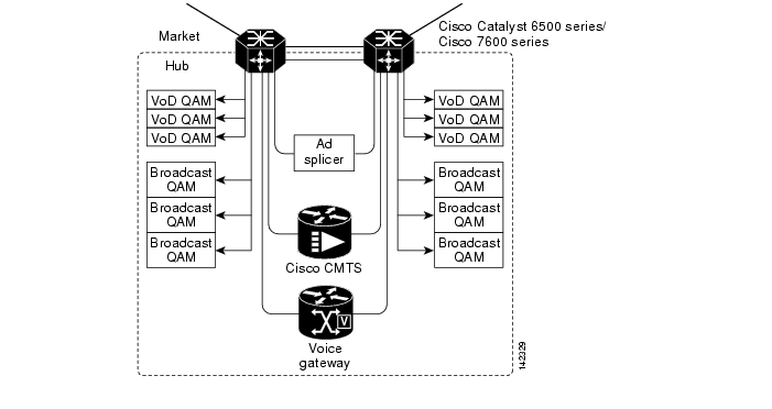
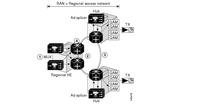
Figure 2-1 illustrates the hub architecture. Ad splicers receive incoming broadcast streams, and splice ads and groom streams into the proper channel lineup for a given neighborhood. The ad splicer in this case is dual-homed.
Broadcast video, HSD, and VoIP trunks are bidirectional 10-GE links. All access links (to the Cisco CMTS, the ad splicer, voice gateways, or EQAM devices) are 1-GE links.
Figure 2-1 Hub Architecture
IP Architecture
Consider a network that is divided into two routing domains in the RAN (see Figure 2-2). One routing domain consists of the loopback interfaces on the ARs and HRs, all physical interfaces on the ARs, and the trunk interfaces on the HRs. These are depicted as the links in (1) and the processes in (1) and (3). (Process 1 is the OSPF process for the RAN. Process 3 is the BGP process for the RAN.) The second routing domain consists of the remaining interfaces on the HRs and the IP addresses of the components in the hub (4). The HRs use OSPF (2) to inject a default route into the hub. Hub devices use OSPF (1) to advertise their loopback, link, and service routes to the HRs.
Figure 2-2 Routing Domains
OSPF process 1, area 0
OSPF process 2, area 1
BGP (iBGP1 )—Used to inject customer routes (statically defined on the Cisco 7600 series or Cisco Catalyst 6500 series into the RAN. Customer routes have next-hop router set to the loopback addresses of both routers.
Hub devices—Oblivious to routing architecture on the RAN. Hub devices see the defaults from the Cisco 7600 series or Cisco Catalyst 6500 series and other hub local routes.
1 Internal BGP. External BGP is referred to as eBGP.
As depicted in Table 2-1, service routes (such as HSD customer prefixes from the Cisco CMTS and all DS/DB device addresses) are advertised in BGP by means of redistribution from the hub interior OSPF process 2. The redistributed prefixes have their next-hop addresses set to a RAN-advertised loopback, so that all service prefixes appear to the RAN to terminate at the HRs in Figure 2-2). If two routers are attached to a hub, then each router advertises its own and the other's hub loopback address, but sets the BGP next-hop addresses to its own hub loopback address.
Within the market network, the two ARs act as BGP route reflectors and all HRs act as route reflector clients. The ARs advertise all internal RAN BGP prefixes plus a default route. They do not advertise eBGP-learned prefixes.
Within the RAN, all ARs are peered with all other ARs. Loopback addresses are used as the router IDs.
Table 2-1 Service Route Configurations
interface loopback 1ip address 30.0.0.1/32ip address 30.0.0.2/32 secondaryrouter ospf 2network <Hub interfaces>1 area 1router ospf 1network 30.0.0.1/32 area 0network 30.0.0.2/32 area 0network <RAN interfaces>2 area 0route-map hub-ospf-to-bgp permit 100match ip address prefix-list hub-pfxset metric 100set ip next-hop 30.0.0.1router bgp 1redistribute ospf 2 route-map hub-ospf-to-bgpinterface loopback 1ip address 30.0.0.2/32ip address 30.0.0.1/32 secondaryrouter ospf 2network <Hub interfaces> area 1router ospf 1network 30.0.0.2/32 area 0network 30.0.0.1/32 area 0network <RAN interfaces> area 0route-map hub-ospf-to-bgp permit 100match ip address prefix-list hub-pfxset metric 100set ip next-hop 30.0.0.2router bgp 1redistribute ospf 2 route-map hub-ospf-to-bgp
1 Provide address, mask, and area for all hub interfaces.
2 Provide address, mask, and area for all RAN interfaces.
Understanding and Optimizing Video Flows
Overview
The video flows can be broken down into DS and DB flows. DS flows (prior to ad insertion) represent the capability of encoding all broadcast content (including analog streams) for transport across the IPmc network to the digital ad-insertion device. Following ad insertion, traffic flows from the ad splicers to the EQAMs. Original analog broadcast streams (digitized for IPmc transport) are converted back to analog streams at the EQAM device. DB flows (requiring no ad insertion) represent the capability of (1) unencrypting broadcast streams upon reception (from satellite or off the air), (2) sending all broadcast content across the IPmc network (unencrypted), and (3) reencrypting the streams at the EQAM device before sending content to the subscriber. There are primary and secondary sources for both DS and DB flows within the RAN.
Advertisements are spliced into live video streams by means of ad splicers. A single market may have as many as 40 ad zones, which are demographically grouped areas of a market that receive the same advertising content. A single hub can serve multiple ad zones. Because each ad splicer serves only a single ad zone, a hub with multiple ad zones contains a set of ad splicers for each ad zone. For example, if Hub A serves three ad zones and requires four splicers to cover the DS channel lineup, there is a total of 12 ad splicers in that hub (four for each of the three ad zones). Ad streams are delivered (by means of unicast) from ad sources in the RAN to the ad splicers in the hub over the bidirectional 10-GE interfaces.
Because of the current inability of the video edge equipment (QAM devices and ad splicers) to support IGMPv3, an ASM model of IPmc is generally being deployed today. The service provider can also deploy an SSM model using the SSM-mapping features supported on the Cisco 7600 series and the Cisco Catalyst 6500 series. Rendezvous points (RPs) are defined statically to provide deterministic flow control across the RAN. The router closest to the source is the RP for that source—providing the added benefit of simplifying network operations and troubleshooting by maintaining the same path for shared and source multicast trees.
Note
DS Flows
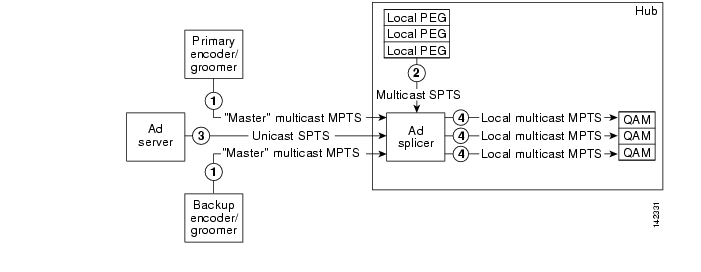
DS flows originate from two sources (primary and secondary). Both flows are delivered to the ad splicers in each hub by means of multicast. The ad splicers splice the advertisement into the program streams before sending out the multicast traffic on a new multicast address to be delivered to the EQAM devices. DS flows can be seen as four component flows (see Figure 2-3):
Figure 2-3 DS Flows
DB Flows
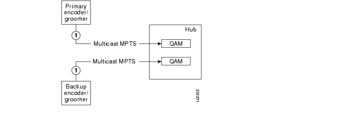
As shown in Figure 2-4, DB flows originate from two sources (primary and secondary). Both flows are delivered to the EQAM devices in each hub by means of multicast. DB flows usually consist of 24 MPTS flows at 38 Mbps each, for a total network load of 912 Mbps.
Figure 2-4 DB Flows
Generic "master" multiprogram transport stream (MPTS) multicast flows arrive from the market's master headend(s) to ad splicers in each hub.
[For more detail, see description of (1) in Figure 2-3.]
Flow Domains
The architecture for distributing broadcast video over the IP network includes breaking down IPmc into three different flow domains from the master HE to the customer, as illustrated in Figure 2-5.
Figure 2-5 IPmc Domains
Note
Optimizing Service Availability
Broadcast video services are inherently real-time. Subscribers who experience an outage in the broadcast service cannot go back and continue where they left off when the outage is over. Also, broadcast services have much higher concurrent usage rates than other video services.
As such, broadcast video is given a high priority among subscriber services. (VoIP has the highest.) Thus the delivery of broadcast services must be highly available and reliable. The ultimate goal is to support hitless failover for IP and IPmc service. However, many customers initially support deploying IP and IPmc services with less than 1-second recovery. To support this, the architecture is being implemented to support resiliency in various places in the RAN.
All service-availability recommendations resulting from testing in this section are in support of Layer 2 and Layer 3 protocol interactions. (It is assumed that Layer 1 transport redundancy is orthogonal to this discussion.) Service availability is defined at the user interface: is there or is there not a picture on residential TV?
Figure 2-6 illustrates how diversity and resiliency, in conjunction with rate limiting, act to maintain high availability. The network links are engineered to 50% utilization. If traffic rates increase and are sustained above 70%, then additional trunks are added to the network.
Figure 2-6 Diversity and Resiliency with Rate Limiting
The following diversity and resiliency topics are discussed below:
Source Diversity
In order to recover quickly from source failures, there are multiple (primary and secondary) satellite and off-air sources per RAN/market, as depicted previously. It is expected that the broadcast video sources (multiplexers and ad splicers) can source one or more IPmc groups per MPTS/SPTS. It is also expected that the IPmc receivers (ad splicers and EQAM devices) can support receiving the same transport stream from different IPmc groups. The intent is for the receiver to be able to identify a faulty stream from the primary source and "switch" immediately to the active secondary source.
Note
Establishing ad splicer redundancy is generally a "manual" process, whereby the ad splicers are configured in an N+1 design. When one ad splicer goes down, it is replaced by the backup ad splicer through a process that reconfigures the backup device with the configuration of the "downed" device. This process eliminates the need to do any reconfiguration of the EQAM itself.
Path Diversity
The purpose of having redundant sources in the RAN/market networks is to support service availability. However, service availability can be affected by least-cost path routing, because both sources may take the same path to a given destination. To alleviate this, the architecture includes three methods to separate the forwarding paths for different sources:
•
Using Static mroutes
Multicast routers maintain state about the incoming and outgoing interfaces for each (source, group) (S,G) pair. This state is used to decide which packets are to be discarded and which are to be forwarded. The table that the router maintains for holding this state information is called the multicast routing table. Each entry in this table corresponds to a unique (S,G) and is referred to as an mroute. Each mroute primarily contains four types of entries:
•
•
•
•
In a ring configuration, the operator simply configures a static mroute to the primary source through the west interface, and a static mroute to the secondary source through the east interface. The following is the syntax of the ip mroute command:
[no] ip mroute source mask [ protocol as-number ] [route-map map ] rpf-address | interface [ distance ]
One drawback to this option is that there is no ability to "reroute" to a given source in the event of a network failure.
Static mroutes must resolve "longest match" criteria, as well as have the lowest administrative distance (lower than that for PIM, BGP, and IGP).
Using MBGP
Multiprotocol Border Gateway Protocol (MBGP), on the other hand, is a bit more complex. MBGP requires the following guidelines:
•
•
•
•
Below is a sample configuration:
router bgp 100no bgp ipv4 uni defaultneighbor MCAST peer-groupneighbor MCAST peer-group next-hop-selfneighbor MCAST peer-group route-reflector-clientneighbor <router 1> peer-group MCASTneighbor <router 2> peer-group MCASTaddress-family ipv4 multicastneighbor <router 1> activateneighbor <router 1> route-map UP-Policy inneighbor <router 2> activateneighbor <router 2> route-map DN-Policy in!route-map UP-Policy permit 10match ip address <primary source>set local-preference <number n>!route-map DN-Policy permit 10match ip address <secondary source>set local-preference <number m>Setting Preferred Routes in EIGRP
Some MSOs currently use OSPF as the preferred IGP. OSPF (being a link-state protocol) does not support the ability to change the metric for an individual route. The solution needs a distance-vector routing protocol with a better administrative distance than OSPF; EIGRP is the logical choice. Table 2-2 lists the default administrative distance values of the protocols that Cisco supports.
Table 2-2 Default Administrative Distances for Supported Protocols
Administrative DistanceConnected interface
0
Static route
11
Enhanced Interior Gateway Routing Protocol (EIGRP) summary route
5
External Border Gateway Protocol (BGP)
20
Internal EIGRP
90
IGRP
100
Open Shortest Path First (OSPF)
110
Intermediate System to Intermediate System (IS-IS)
115
Routing Information Protocol (RIP)
120
Exterior Gateway Protocol (EGP)
140
On Demand Routing (ODR)
160
External EIGRP
170
Internal BGP
200
Unknown
2552
1 Static route pointing is always 1, regardless of whether the pointing is to a next-hop IP address or to an outgoing interface.
2 If the administrative distance is 255, the router does not believe the source of that route and does not install the route in its routing table.
There are two primary methods for setting a preferred route in EIGRP:
•
•
Note
http://www.cisco.com/en/US/tech/tk365/technologies_tech_note09186a00800c2d96.shtmlPath Resiliency
Path resilience relies on the network's ability to reconverge to an alternate path for the following conditions:
•
•
Note
PortChannel and Equal-Cost Multipath
There may be instances in which parallel paths are used to interconnect some aggregation routers and hub routers. PortChannel (or EtherChannel) facilitates the bundling of multiple links into a single Layer 3 logical interface. (The algorithm works best with a specific number of ports in the channel. The recommended numbers of ports are 2, 4, or 8.) Equal-cost multipath (ECMP) facilitates the bundling of multiple Layer 3 physical links.
There are things to consider:
•
•
One advantage with PortChannel is the ability in Cisco IOS Release 12.2(18)SXF to use the EtherChannel Min-Link feature to specify a minimum number of ports for a PortChannel to be considered a valid path. This feature allows the user to set a minimum threshold for the number of links in an EtherChannel, so that if fewer than the specified number of links are available, the port channel interface fails over to a standby EtherChannel.
Note
One advantage of ECMP is the ability to load balance based on (*,G) or (S,G) state. Another advantage of ECMP is its efficiency for handling IPmc replication.
However, there is no mechanism to "remove" an ECMP group from the forwarding table based on a minimum number of links. This can be resolved by using an N+1 redundancy model, where the total number of links in an ECMP group is at least one greater than the minimum number of links required to transport the services.
Note
[no] ip multicast [vrf vrf-name] multipath
For more information, see the following:
http://www.cisco.com/en/US/products/sw/iosswrel/ps1835/products_command_reference_chapter09186a00800ca76c.html#wp1078508IGP Fast Convergence
With the understanding that IPmc forwarding relies on IP reachability, then fast recovery of IPmc requires fast recovery of IP. Internal Gateway Protocol (IGP) fast convergence supports this objective in the solution.
The following URLs are helpful resources for fast convergence:
•
http://www.cisco.com/en/US/partner/products/sw/iosswrel/ps1838/prod_bulletin0900aecd80327e21.html
•
http://www.cisco.com/en/US/partner/products/hw/switches/ps708/prod_release_note09186a00801c8339.html
Note
Note
•
•
•
•
•
http://www.cisco.com/en/US/partner/products/ps6017/products_feature_guide09186a00803fbe87.html
•
http://www.cisco.com/en/US/tech/tk365/technologies_white_paper0900aecd80244005.shtml
Note
Hardware Rate Limiters
This section presents the following topics:
•
•
Introduction
As the service provider industry moves rapidly toward deployment of IP-based video services to consumers, IP transport networks are being engineered to handle extremely high levels of video traffic. These high levels of traffic introduce new service risks if traffic that is normally switched in hardware on routing platforms inadvertently reaches the CPU for processing. This section addresses the operation and use of security mechanisms on the Cisco 7600 platform known as hardware rate limiters (HWRLs).
Note
With the threat of distributed denial of service (DDoS) attacks and misconfigurations on the routers and switches used for forwarding the video service, there is a need to rate-limit traffic that could adversely affect service delivery. It is assumed that any method of high-bandwidth traffic injection (either from the Internet or from a residential subscriber) is being marked/policed at the edges of the network, limiting trunk congestion in the network. However, this does not solve the problem of sending packets into the network that are required to be process-switched (rather than switched in hardware), and therefore taking processing resources away from critical network-control functions.
The Cisco 7600 series with the Supervisor Engine 720 has several mechanisms for protecting the control and management plane from performance impacts resulting from DDoS attacks and network misconfigurations.
Note
Caution
Control Plane and Management Plane Protection
The vast majority of traffic generally travels through the router via the data plane; however, the switch processor (SP) and the route processor (RP) must handle certain packets. These packets are referred to as control plane packets in the remainder of the document.
The SP and RP are critical for system operations. In order to protect the switch's control plane effectively, it is first important to profile the CPU traffic to understand better which types of packets should be allowed to the CPU and how critical each of these packet types are. Packets bound to the CPU include the usual control and management plane traffic such as the following:
•
•
•
•
•
•
Some data-plane traffic may have to be processed in software as well. This type of traffic is referred to as data-plane "punt" traffic. Examples of software-processed data-plane packets include the following:
•
•
•
•
•
•
A DoS attack targeting the Cisco 7600 series, which can be perpetrated either inadvertently or maliciously, typically involves high rates of traffic destined to the SP or RP itself. This can result in the following symptoms:
•
•
•
•
•
•
•
The Cisco 7600 series support a two-level defense that uses (1) control-plane policing (CoPP; see Note below) and (2) special-case CPU hardware rate limiters (HWRLs). CoPP is applied in hardware on a per-forwarding-engine basis at the Policy Feature Card (PFC) and Distributed Forwarding Card (DFC). The special-case CPU rate limiters are platform dependent, and are applied to rate-limit process-switched traffic going to the SP or RP.
Note
Hardware rate limiters don't provide the same level of traffic-control granularity as CoPP, and are thus useful for cases where hardware CoPP cannot be used to classify particular types of traffic, or when the need to rate-limit the traffic is not dependent on the source and destination addresses. Such special packet types include packets with TTL equal to 1, packets that fail the MTU check, packets with IP options, and IP packets with errors.
CoPP and HWRL should be used in conjunction. However, be aware that the hardware rate limiters override the hardware CoPP policy for packets matching the rate limiter's criteria. That is, if traffic matches a special-case rate limiter, it is never compared against the hardware CoPP policy. It is compared only against the software CoPP policy. Therefore, note the following Caution.
Caution
Note the following:
•
•
There is no performance penalty for using all ten HWRLs. Hardware rate limiters are supported in all available Supervisor 720 Cisco IOS versions. However, some rate-limiters have been added over time.
•
Solution-Specific HWRL Details and Examples
This section introduces a variety HWRLs and the commands to configure them, provides additional detail, and presents examples of HWRL configurations suitable to the solution. Testing has verified that the HWRL recommendations that follow do not affect the ability to deliver a residential video service.
Note
Table 2-3 shows the hardware-based rate limiters available on the Supervisor Engine 720, along with their descriptions. To rate-limit processed-switched traffic, HWRLs are implemented by means of the MultiLayer Switching (MLS) limit command), and operate at the switch chassis level.
Caution
Table 2-3 Hardware Rate Limiters for the Supervisor Engine 720
Unicast
ACL Input
(NAT, TCP int, reflexive ACLs, logon ACLs)
ACL Output
(NAT, TCP int, reflexive ACLs, logon ACL)
CEF Glean
(ARP packets)
CEF Receive
(Traffic destined to the router)
ICMP No Route
(ICMP unreachables for unroutable packets)
Rate-Limiting ICMP Unreachable Packets—No Route and ACL Drop (Unicast)
ICMP Redirect
(Packets that require ICMP redirects)
IP Errors
(Packets with IP checksum or length errors)
IP Features
(Packets that support security, such as CBAC, auth-proxy, and IPsec traffic)
IP Options (B/BXL)
(Unicast traffic with IP options set)
RPF Failure
(Packets that fail uRPF check)
VACL Logging
(CLI notification of VACL denied packets)
Multicast
Directly Connected
(Local multicast on connected interface)
IGMP
(IGMP packets)
IP Options (B/BXL)
(Multicast traffic with IP options set)
Multicast FIB-Miss
(Packets with no mroute in the FIB)
Partial Shortcut
(Partial shortcut entries)
Non-RPF Interface
Layer 21
L2PT
(L2PT encapsulation/decapsulation)
PDU
(Layer 2 PDUs)
General2
MTU Failure3
(Packets requiring fragmentation)
TTL Failure2
(Packets with TTL less than or equal to 1)
1 See Notes below.
2 Shared across the 10 hardware rate limiters.
3 Available only with the DFC3B and DFC3BXL.
Note
Router(config)#mls rate-limit layer2 pdu 100
04:23:12: %MLS_RATE-4-NOT_SUPPORTED: This functionality is not configurable.
Note
http://www.cisco.com/en/US/products/hw/routers/ps368/products_configuration_guide_chapter09186a008016113c.html#wp1051977Rate-Limiting Ingress/Egress ACL Bridged Packets (Unicast)
Summary
This limits packets that are sent to the CPU as a result of an inbound/outbound (ingress/egress) access control list (ACL). The bridged packets are sent when the log keyword is used at the end of an Access Control Entry (ACE).
Details
ACEs with the log keyword are processed in software on the CPU, but the rest of the ACL is processed in hardware on the DFC. This HWRL can also be used to rate-limit the first packet of a flow for hardware-accelerated features such as NAT, WCCP, CBAC, Auth-Proxy, and TCP Intercept.
Note
The following configuration creates an egress ACE that punts packets to the CPU if conditions are met:
access-list 20 permit 192.168.0.0 0.0.31.255access-list 20 permit 192.168.0.0 0.0.0.255access-list 20 deny any any loginterface GigabitEthernet 7/1ip address 10.0.1.2 255.255.255.252ip access-group 20 outDefault
By default, this HWRL is disabled.
Recommendation
Cisco recommends that the ACE log keyword be used sparingly, and only for deny ACEs if possible.
Examples
The following example shows how to rate-limit the unicast packets from an ingress ACL bridge result to 1000 packets per second, and 10 packets in burst:
Router(config)# mls rate-limit unicast acl input 1000 10The following example shows how to rate-limit the unicast packets from an ingress ACL bridge result to the same rate (1000 pps and 10 packets in burst) for egress ACL bridge results:
Router(config)# mls rate-limit unicast acl output 1000 10If the values of the rate limiter are altered on either the ingress or the egress when both are enabled, both values are changed to that new value.
In the following example, the output rate is changed to 40000 pps:
Router(config)# mls rate-limit unicast acl output 40000 10When you enter the show mls rate-limit command, both the ACL bridged in and the ACL bridged out display the new value of 40000 pps:
Router# show mls rate-limitRate Limiter Type Status Packets/s Burst--------------------- ---------- --------- -----MCAST NON RPF Off - -MCAST DFLT ADJ On 100000 100MCAST DIRECT CON Off - -ACL BRIDGED IN On 40000 10ACL BRIDGED OUT On 40000 10IP FEATURES Off...Rate-Limiting FIB (CEF) Glean Traffic (Unicast)
Summary
This does not limit Address Resolution Protocol (ARP) traffic, but rather provides the capability to rate-limit traffic that requires address resolution and requires that it be sent to the MSFC.
Details
Consider a router directly connected to a subnet with several hosts. The FIB table on the router maintains a prefix for the subnet instead of for individual host prefixes. This subnet prefix points to what is known as a "glean" adjacency. When traffic contains the destination of a host on a subnet that is locally connected to the router, but no ARP entry exists for that specific destination host, because the MAC address of the destination host is unknown, the glean adjacency is hit in the forwarding table and the traffic is sent directly to the CPU for ARP resolution.
This HWRL does not limit ARP packets, but instead provides the capability to rate-limit traffic that requires address resolution and requires that it be sent to the CPU. This reduces the possibility of an attacker overloading the CPU with such traffic needing ARP resolution.
Default
By default, this HWRL is disabled.
Recommendation
When this HWRL is enabled, the egress security ACL (and egress QoS) of the ingress interface is applied, resulting in dropped packets. The current workaround is either to (1) relax the egress security ACLs of ports facing the PCs or server, or (2) disable the HWRL. Ports facing only routers do not experience this issue, because routing protocols guarantee that ARP entries always exist for routers.
Note
Example
The following example shows how to rate-limit this traffic to the MSFC to 20000 pps and a burst of 60:
Router(config)# mls rate-limit unicast cef glean 20000 60Rate-Limiting FIB (CEF) Receive Packets (Unicast)
Summary
This limits all unicast packets that are directed to the router's local IP addresses.
Caution
Details
Caution
Default
By default, this HWRL is disabled.
Recommendation
Cisco recommends using CoPP, rather than enabling this HWRL, for more granular control-plane protection.
Example
The following example shows how to rate-limit traffic to 25000 pps with a burst of 60:
Router(config)# mls rate-limit unicast cef receive 25000 60Rate-Limiting ICMP Unreachable Packets—No Route and ACL Drop (Unicast)
Summary
This limits traffic that requires the RP CPU to generate ICMP unreachable packets. It does not rate-limit ICMP traffic coming into the router.
Details
For example, when a host sends packets through a router in a suboptimal route path (for a destination not in the routing table, or that is denied by a security ACL or that matches a null route), the CPU sends ICMP unreachable messages to the host to correct the route path. If this traffic occurs continuously and is not rate-limited, the CPU continuously generates ICMP Unreachable messages, which increases CPU utilization.
If the no ip unreachables command is configured and an ACL is applied on an interface, then for that interface deny access control entries (ACEs) are processed in software on the CPU, and permit ACEs are processed in hardware.
Note the following:
•
mls rate-limit unicast ip icmp unreachable acl-drop 0
•
•
Default
By default, this HWRL is disabled.
Recommendation
This HWRL is recommended to protect against large VoD streams that have routing misconfigurations, as well as against DoS flooding attacks.
Examples
The following example shows how to rate-limit the packets resulting from an ACL drop to 100 pps and a burst of 10:
Router(config)# mls rate-limit unicast ip icmp unreachable acl-drop 100 10The following example shows how to rate-limit the packets that require generation of ICMP Unreachable messages because of a FIB miss (no route) to 80000 pps and burst to 70:
Router(config)# mls rate-limit unicast ip icmp unreachable no-route 80000 70Rate-Limiting ICMP Redirect Messages (Unicast)
Summary
This allows you to rate-limit ICMP traffic.
Details
When a host sends packets through a nonoptimal router, the CPU sends ICMP-redirect messages to the host to correct its sending path. If this traffic occurs continuously, and is not rate-limited, the CPU continuously generates ICMP-redirect messages. To disable this behavior, apply the no ip icmp redirect command to the desired interface.
Default
By default, this HWRL is enabled.
Recommendation
This HRWL is not needed in cases where the no ip icmp redirect command is used in standard configurations].
Example
The following example shows how to rate-limit the ICMP redirects to 20000 pps, with a burst of 20 packets:
Router(config)# mls rate-limit unicast ip icmp redirect 20000 20Rate-Limiting IP Error Packets (Unicast)
Summary
This limits the packets with IP checksum and length errors.
Details
When a packet reaches the PFC3 with an IP checksum error or a length inconsistency error, it must be sent to the CPU for further processing. An attacker might use the malformed packets to carry out a DoS attack, but the network administrator can configure a rate for these types of packets to protect the control path.
The following messages are seen in the logs if a malformed IP packet is received and the global service internal command is configured on the router:
Aug 23 15:03:03.747 UTC: %EARL_L3_ASIC-DFC2-3-INTR_WARN: EARL L3 ASIC: Non-fatal interruptPacket Parser block interruptAug 23 15:03:15.643 UTC: %MLS_STAT-DFC2-4-IP_CSUM_ERR: IP checksum errorsAug 23 15:46:43.553 UTC: %EARL_L3_ASIC-DFC2-3-INTR_WARN: EARL L3 ASIC: Non-fatal interruptPacket Parser block interruptAug 23 15:46:45.637 UTC: %MLS_STAT-DFC2-4-IP_CSUM_ERR: IP checksum errorsA high rate of these malformed packets affects CPU utilization.
Default
By default, this HWRL is enabled.
Recommendation
IP errors can occur at very low frequency and should not affect the CPU. This HWRL shares the same state and values as the uRPF Failure, ICMP Unreachable, and IP Error rate limiters (which are recommended), and is on by default.
Example
The following example shows how to rate-limit IP errors sent to the MSFC to 100 pps with a burst of 10 packets:
Router(config)# mls rate-limit unicast ip errors 100 10Rate-Limiting IP Features (Unicast)
Summary
This limits the number of packets sent first to the CPU to support security features, reducing the potential for overloading.
Details
The security features include authentication proxy (auth-proxy), IPsec, and inspection.
Authentication proxy is used to authenticate inbound or outbound users or both. These users are normally blocked by an access list, but with auth-proxy, the users can bring up a browser to go through the firewall and authenticate on a TACACS+ or RADIUS server (based on the IP address). The server passes additional access list entries down to the router to allow the users through after authentication. These ACLs are stored and processed in software, and if there are many users utilizing auth-proxy, the CPU may be overwhelmed. Rate limiting would be advantageous in this situation.
Note
Default
By default, this HWRL is disabled.
Recommendation
Cisco recommends using CoPP, rather than this HWRL, to control authentication traffic.
Example
The following example shows how to rate limit the security features to the CPU to 100000 pps with a burst of 10 packets:
Router(config)# mls rate-limit unicast ip features 100000 10Rate-Limiting IP Options (Unicast)
Summary
This limits packets directed to the CPU for IP options processing. This includes packets that are tagged for loose or strict routing or that have the record-route option set.
Details
This HWRL is available only on systems running in PFC3B or PFC3BXL mode. It is not available on systems running PFC3A mode.
Default
By default, this HWRL is disabled.
Recommendation
Cisco recommends that this HWRL be used where PFC3B or PFC3BXL modes are available.
Example
The following example shows how to rate-limit traffic to 100 pps with a burst of 10:
Router(config)# mls rate-limit unicast ip options 100 10Rate-Limiting uRPF Check Failure Packets (Unicast)
Summary
This limits packets that are sent to the CPU because they failed the Unicast Reverse Path Forwarding (uRPF) check. The uRPF checks validate that incoming packets on an interface are from a valid source, which minimizes the potential threat of DoS attacks from users using spoofed addresses.
Details
When spoofed packets fail the uRPF check, those failures can be sent to the CPU by an ACL that directs it. The uRPF check rate limiters allow you to rate-limit the packets per second that are bridged to the CPU when an ACL fails to eliminate an overload.
The uRPF checks validate that incoming packets on an interface are from a valid source, which minimizes the potential threat of DoS attacks from spoofed addresses. In a SUP720/PFC3A system (or a Sup7203BXL with DFC3A modules present), the use of an ACL can cause the uRPF check to become software processed. When an ACL is configured in the uRPF command, the PFC3 determines whether or not traffic is permitted by the ACL, as shown below.
interface GigabitEthernet7/1description Link to CMTSip address 10.0.1.2 255.255.255.0ip verify unicast source reachable-via rx 20ip ospf cost 2endaccess-list 20 permit 192.168.124.0 0.0.0.255access-list 20 permit 192.168.123.0 0.0.0.255access-list 20 deny any any logPackets permitted by the ACL are forwarded in hardware without a unicast RPF check, whereas packets denied by the ACL are sent to the MSFC-RP for a Unicast PRF check. Because the packets in a denial-of-service attack typically hit the deny ACE and are sent to the MSFC-RP for the Unicast PRF check, they can overload the CPU. On a Sup720 system you can rate-limit the amount of traffic being bridged to the MSFC-RP as a result of ACL failed.
•
http://www.cisco.com/univercd/cc/td/doc/product/software/ios122/122cgcr/fsecur_c/fothersf/scfrpf.htm
•
Note
Default
By default, this HWRL is disabled.
Recommendation
This HWRL is recommended. Enable this with a rate limit of 100 pps and a burst limit of 10 packets.
Example
The following example shows how to rate-limit the uRPF check failure packets sent to the MSFC to 100 pps with a burst of 10 packets:
Router(config)# mls rate-limit unicast ip rpf-failure 100 10Rate-Limiting VACL Logging Messages (Unicast)
Summary
This limits packets sent to the CPU because of VLAN ACL (VACL) logging, to ensure that the CPU is not overwhelmed with logging tasks.
Details
VLAN ACLs are used to prevent individual IP hosts from communicating with each other within a single VLAN or across different VLANs. They are also used to filter and capture packets for Cisco 7600 service modules. Packets that are sent to the CPU because of VLAN-ACL logging can be rate limited to ensure that the CPU is not overwhelmed with logging tasks. VACLs are processed in hardware, but the CPU does the logging. When VACL logging is configured on the router, IP packets that are denied in the VACL generate log messages.
•
Default
By default, this HWRL is enabled.
Recommendation
This HWRL is not needed if VACLs are not used.
Example
The following example shows how to rate-limit logging requests to 5000 pps (the range for this rate limiter is from 10 to 5000 pps):
Router(config)# mls rate-limit unicast acl vacl-log 5000Rate-Limiting Directly Connected Packets (Multicast)
Summary
This controls the rate at which Register messages are encapsulated on the first hop (source) router and forwarded to the RP before any receivers have joined.
Details
The multicast connected rate-limiter is designed to control the rate at which Register messages are encapsulated on the first hop (source) router and forwarded to the RP before any receivers have joined. Once a receiver joins the tree, an mroute is put into the FIB and the multicast traffic on that tree is then hardware switched, so this rate limiter is no longer used. This HWRL is useful when several high-rate sources start sending traffic, to limit the CPU utilization until the flow is installed in hardware. This can occur when the RP is not defined to be the source router (SR), as a result of a misconfiguration.
Note
Default
By default, this HWRL is disabled.
Recommendation
Cisco recommends the use of this HWRL to protect against situations where a new source begins transmitting at a high rate. This could be the case where the RP is not defined to be the source router, as a result of misconfiguration.
Example
The following example shows how to rate-limit the multicast packets to 100 pps with a burst of 250:
Router(config)# mls rate-limit multicast ipv4 connected 100 250Rate-Limiting Layer 2 IGMP Snooping Traffic (Multicast)
Summary
This limits the number of Layer 2 IGMP packets destined for the supervisor engine when IGMP snooping is enabled.
Details
IGMP snooping listens to IGMP messages between the hosts and the supervisor engine, and is used to track which local interfaces in a VLAN should receive multicast flows for different groups.
Because of the way that incoming PIM packets are handled in hardware on the Supervisor Engine 720, this rate limiter is also effective for controlling the rate at which received PIM Register messages are sent to the CPU. This can be an effective filter against inadvertent or rogue unicast PIM Register messages being directed at an unsuspecting router.
Note
Note
Default
By default, this HWRL is disabled.
Recommendation
In multicast networks a high number of IGMP messages do not normally hit the router. However, because this HWRL is also effective in protecting against unicast PIM Register messages being directed at a router, Cisco recommends using this HWRL as a protection against misconfigurations or denial of service (DoS) attacks.
Example
The following example shows how to rate-limit IGMP snooping traffic to 1000 pps and a burst of 10 packets:
Router(config)# mls rate-limit multicast ipv4 igmp 1000 10Rate-Limiting IP Options Packets (Multicast)
Summary
This limits packets directed to the CPU for IP Options processing. This includes packets that are tagged for loose or strict routing or that have the record-route option set.
Details
This HWRL is available only on systems running in PFC3B or PFC3BXL mode. It is not available on systems running PFC3A mode.
Note
Default
By default, this HWRL is disabled.
Recommendation
Cisco recommends this HWRL be used where systems are running in PFC3BXL mode. It cannot be used in systems that are running in PFC3A mode.
Example
The following example shows how to rate-limit multicast IP options traffic to 100 pps and a burst of 10 packets:
Router(config)# mls rate-limit multicast ipv4 ip-options 100 10Rate-Limiting FIB Miss Packets (Multicast)
Summary
This HWRL allows you to control multicast traffic that must be punted to the CPU that does not match an existing hardware entry in the mroute table. Packets that do not match an existing hardware (*,G) or (S,G) entry must be sent to the CPU for processing.
Details
The Forwarding Information Base (FIB) and Cisco Express Forwarding (CEF) tables contain information programmed into hardware about how to forward traffic, thus relieving the CPU of having to look up a destination for every packet in a flow. Keeping in mind that multicast lookups occur on a source, not on a destination, the CEF entries for multicast flows point to the upstream Reverse Path Forwarding (RPF) interface for a source [for (S,G) flows] or an RP [for (*,G) flows], rather than to a unicast flow's outgoing (forwarding) interface. A (*,G) or (S,G) entry can be programmed in hardware only if the unicast routing table can resolve the RPF interface of the RP or source address.
Hardware entries can be seen with the show mls cef ip multicast tcam group command. An entry with a source address of 0.0.0.0 corresponds to the (*,G) entry. Note the following example.
Router# show mls cef ip multicast tcam 239.16.1.40Index Group Source RPF/DF Interface524638 239.16.1.40 172.16.3.2 Te4/11048258 239.16.1.40 0.0.0.0 Te4/1There are potentially several situations where a FIB-miss could occur, such as where a static RP address is misconfigured, where the routing table has not fully converged after a network topology change, or following a clear ip mroute command.
Note
Note
Default
By default, this HWRL is enabled.
Recommendation
Cisco recommends that this HWRL be enabled at a very low rate (100 pps). In an Any Source Multicast (ASM) network, the FIB-miss adjacency is often hit because the router cannot switch traffic from the shared tree to the source tree because of routing misconfiguration or instability. If the rate for this HWRL is kept low, the router simply continues to forward traffic on the shared tree.
Example
The following example shows how to rate-limit the multicast FIB miss packets to 100 pps with a burst of 10:
Router(config)# mls rate-limit multicast ipv4 fib-miss 100 10Rate-Limiting Partially Switched Flows (Multicast)
Summary
This limits the flows destined to the CPU for forwarding and replication.
Details
A multicast flow can be either fully or partially hardware switched or software switched. For a given multicast traffic flow, if at least one outgoing Layer 3 interface is multilayer switched, and at least one outgoing interface is not multilayer switched (no H-bit is set for hardware switching), the particular flow is considered partially switched, or" Partial-SC" (for partial shortcut). (See below.)
The output of the show ip mroute command indicates the current state of each flow.
•
•
•
Because the OIFs that have the H-bit flag are switched in hardware, and remaining traffic is switched in software through the MSFC3, it may be desirable to rate limit the flow destined to the MSFC3 for forwarding and replication, which might otherwise increase CPU utilization.
The following shows how to identify a partially switched flow:
Router# show ip mroute(*, 239.19.252.2), 1w5d/00:03:23, RP 172.16.9.69, flags: SJCIncoming interface: TenGigabitEthernet4/2, RPF nbr 172.16.9.169, Partial-SCOutgoing interface list:TenGigabitEthernet4/1, Forward/Sparse, 16:55:37/00:03:23, HGigabitEthernet3/3, Forward/Sparse, 1w5d/00:02:31, HGigabitEthernet2/14, Forward/Sparse, 1w5d/00:01:14, H(172.16.11.171, 239.19.252.2), 1w5d/00:02:50, flags: TIncoming interface: TenGigabitEthernet4/2, RPF nbr 172.16.9.169, RPF-MFDOutgoing interface list:TenGigabitEthernet4/1, Forward/Sparse, 16:55:37/00:03:23, HGigabitEthernet2/14, Forward/Sparse, 1w5d/00:01:14, HGigabitEthernet3/3, Forward/Sparse, 1w5d/00:02:31, H
Note
Note
Default
By default, this HWRL is enabled.
Recommendation
Because there are a number of situations in any source multicast (ASM) networks in which flows can be in a partial shortcut state, Cisco recommends the use of this HWRL.
Example
The following example shows how to rate-limit the partial shortcut flows to 500 pps with a burst of 250 packets:
Router(config)# mls rate-limit multicast ipv4 partial 500 250Rate-Limiting Non-RPF Interfaces (Multicast)
Summary
This limits non-RPF traffic that is periodically leaked from a hardware-switched flow to the CPU.
Details
Once an (S,G) state is programmed in hardware on the line card, NetFlow hardware on the DFC3 is used to drop flows appearing on non-RPF interfaces. This HWRL is applied only to non-RPF traffic that is periodically leaked from a hardware switched flow to the CPU.
Note
Note
Default
By default, this HWRL is enabled.
Recommendation
Cisco does not recommend the use of this HWRL, because the rate-limiting behavior is not deterministic and may cause convergence speed issues.
Example
This example shows how to set the rate limiters for the IPv4 multicast packets failing the uRPF check:
Router(config)# mls rate-limit multicast ipv4 non-rpf 100Rate-Limiting Layer 2 Protocol Tunneling Packets
Summary
This limits the Layer 2 protocol tunneling packets, which include control PDUs, CDP, STP, and VTP packets destined for the supervisor engine.
Details
These packets are encapsulated in software (rewriting the destination MAC address in the PDU), and then forwarded to a proprietary multicast address (01-00-0c-cd-cd-d0).
Default
By default, this HWRL is disabled.
Recommendation
Cisco does not recommend the use of this HWRL where Layer 2 protocols are not allowed on uncontrolled (customer-facing) interfaces in the RAN.
Example
The following example shows how to rate-limit Layer 2 protocol tunneling packets to 10000 pps with a burst of 10 packets:
Router(config)# mls rate-limit layer2 l2pt 10000 10Rate-Limiting Layer 2 PDU Packets
Summary
This limits the number of Layer 2 Protocol Data Unit (PDU) packets (including BPDUs, DTP, PAgP, CDP, STP, and VTP packets) destined for the supervisor engine and not the CPU.
Details
This HWRL cannot be enabled if the Supervisor Engine 720 is operating in truncated mode.
Note
Default
By default, this HWRL is disabled.
Recommendation
Cisco does not recommend the use of this HWRL where Layer 2 protocols are not allowed on uncontrolled (customer-facing) interfaces in the RAN.
Caution
Example
The following example shows how to rate-limit Layer 2 PDUs to 20000 pps with a burst of 20 packets.
Router(config)# mls rate-limit layer2 pdu 20000 20Rate-Limiting MTU Failure Packets
Summary
This limits packets that fail an MTU check. These are sent to the CPU and might overwhelm it.
Details
Similar to the TTL failure rate limiter, the rate limiter for MTU failures is supported for both unicast and multicast traffic. An MTU failure occurs when a packet whose DF (Don't Fragment) bit is set cannot be transmitted on an outbound interface because the MTU of the link is smaller than the packet size. The packet must then be sent to the CPU for further handling.
Default
By default, this HWRL is disabled.
Recommendation
This HWRL should not be needed where all interfaces in the RAN are either 1 GE or 10 GE and have a uniform MTU. If tunneling protocols are used in such a network, this HWRL may be useful.
Example
The following example shows how to rate-limit packets failing the MTU failure check from being sent to the MSFC to 100 pps with a burst of 10:
Router(config)# mls rate-limit all mtu 100 10Rate-Limiting TTL Failure Packets
Summary
This limits packets that are sent to the MSFC because of a time-to-live (TTL) check failure (the packet's TTL has expired). As indicated by the all keyword in the following example, this rate limiter applies to both multicast and unicast traffic.
Details
TTL failure commonly occurs when routing loops are present in the network. However, some edge devices such as video encoders or servers can be misconfigured to source traffic with a low TTL value, resulting in a TTL failure before the packet reaches its destination. This situation results in high CPU utilization unless the TTL Failure HWRL is configured. This HWRL can be safely set to a very low number, because TTL-failed packets are dropped regardless and should be handled in hardware for CPU protection.
Default
By default, this HWRL is disabled.
Recommendation
This HWRL is recommended to protect against high-bandwidth (video) sources with misconfigured TTL that introduce a high rate of traffic into the network.
Example
The following example shows how to rate-limit the TTL failures to 100 pps with a burst of 10:
Router(config)# mls rate-limit all ttl-failure 100 10Tips for Using HWRLs
Keep the following in mind when using HWRLs:
•
•
•
•
default mls rate-limit multicast connected•
Note
http://www.cisco.com/en/US/products/hw/routers/ps368/products_configuration_guide_chapter09186a0080160ecc.html•
•
•
Note
•
•
•
•
•
•
•
HWRL Resources
For troubleshooting information, see Viewing HWRL Counters.
For additional information on HWRLs, refer to the following documents at their respective URLs:
•
http://www.cisco.com/univercd/cc/td/doc/product/core/cis7600/software/122sx/swcg/index.htm
•
http://www.cisco.com/univercd/cc/td/doc/product/lan/cat6000/122sx/cmdref/m1.htm#wp1497651
•
http://www.cisco.com/en/US/products/hw/switches/ps708/products_white_paper0900aecd802ca5d6.shtml
QoS Fundamentals
When broadcast and on-demand video is carried over an IP network, there is an assumption that the video quality is not degraded when compared to other video transport alternatives, such as MPEG-2 streams transmitted directly over a QAM carrier as is done in cable networks today. To ensure that the degradation in video quality due to the IP transport network is negligible from a subscriber's point of view, most carriers allow the transport network to introduce (at most) one visible degradation in video quality about every two hours.
Note
While this end-user requirement is similar to what is currently accepted for voice over IP services, the resulting allowed drop requirement for an IP transport network designed for video services is much more stringent than the requirement for VoIP. The reason for the difference in drop requirements between VoIP and video can be attributed to the support of algorithms used in VoIP that are designed to conceal dropouts in the voice signal caused by lost packets in the IP network. The result is that the IP network can drop a single voice packet without the listener noticing any degradation in voice quality. However, there is no such concealment algorithm for video. The result is that when the IP transport network drops a single video packet, there is a visible degradation of video quality of anywhere from a single frame up to one second, depending on the information that is lost.
Assuming a random loss pattern for video and voice packets, the resulting allowed drop rates for video and voice services are, respectively, 10-6 and 10-2. The lower allowed drop rate for video means that both drops cause by congestion and drops caused by bit errors on physical links must be taken into account when one designs a transport network for video services.
The DiffServ architecture defines packet marking and scheduling behaviors that can be used ensure that video flows meet the required 10-6 drop rate when links are congested. Video over IP is typically carried in ~1400-byte packets. If bit errors are assumed to be distributed randomly, the resulting requirement for transport links is to ensure a bit error rate (BER) of < 10-10.
The BER on optical links can be engineered to 10-14 or less by ensuring a high signal-to-noise ratio on those links. Thus video quality due to bit errors on these links should not be an issue.
Note
Because broadcast video, HSD, and VoIP share the same links, it is important to understand how to classify and queue traffic appropriately in order to eliminate the effect high link utilization has on the priority services (broadcast video and VoIP). Table 2-5 presents the details of QoS class and queue assignment for various traffic types.
Table 2-5 QoS Class and Queue Assignment for Various Traffic Types
Suspect
Unknown
(assume
1/2 UDP,
1/2 TCP)Unknown
(assume unicast)Unknown
(assume
1/4 100,
1/4 250,
1/4 500,
1/4 1000>/= 0.1 Gbps
0/1
HSD
IMIX1
Unicast
IMIX
>/= 4 Gbps
1/1
Gaming
Unknown
(assume UDP)Unknown
(assume unicast)Unknown
(assume 500)Unknown
(assume
</= 0.25 Gbps2/1
Network management
Unknown
(assume
1/2 UDP,
1/2 TCP)Unknown
(use unicast to simplify)100
Unknown
(assume
0.1 Gbps3/2
VoIP control
TCP
Unicast
64
</= 0.2 Gbps
4/2
Broadcast video
UDP
Multicast
1500
2.5 Gbps
6/3
Ad insertion
UDP
Unicast
1500
2 Gbps
6/3
VoIP bearer
UDP
Unicast
160
0.5 Gbps
5/8
1 Internet mix traffic
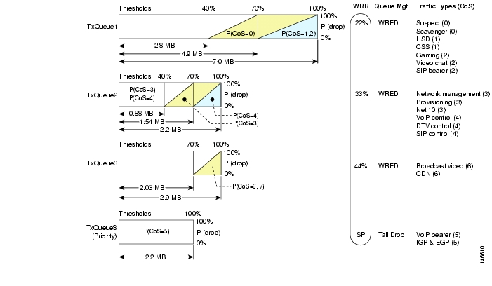
However, queuing alone is not sufficient, as different classes of traffic share queues. Therefore, one must understand how to set class limits/thresholds properly within each queue. Figure 2-7 provides an example of defining traffic-class and queue thresholds.
Figure 2-7 Traffic Class and Queue Thresholds
Note the following:
•
•
•
Caution
Tip
(1) If the servers support the functionality, configure the servers themselves to set the DSCP bits, trusting them on the network edge devices.
(2) Classify the traffic appropriately by setting the DSCP bits on the network edge devices.
For more information, see "Implementing Quality of Service Policies with DSCP" at the following URL:
http://www.cisco.com/en/US/tech/tk543/tk757/technologies_tech_note09186a00800949f2.shtml
Note
Upgrading the Network: Migrating from ASM to SSM
IP multicast delivery modes differ only for the receiver hosts, not for the source hosts. A source host sends IP multicast packets with its own IP address as the IP source address of the packet and a group address as the IP destination address of the packet. The following topics are presented below.
Any Source Multicast
In the Any Source Multicast (ASM) delivery mode, an IP multicast receiver host can use any version of IGMP to join a multicast group. This group is notated as G in the routing table state notation. By joining this group, the receiver host is indicating that it wants to receive IP multicast traffic sent by any source to group G. The network delivers IP multicast packets from any source host with the destination address G to all receiver hosts in the network that have joined group G.
ASM requires group address allocation within the network. At any given time, an ASM group should be used by only a single application. When two applications use the same ASM group simultaneously, receiver hosts of both applications receive traffic from both application sources. This may result in unexpected excess traffic in the network. This situation may cause congestion of network links and malfunction of the application receiver hosts.
Note
Source Specific Multicast
Source Specific Multicast (SSM) is a datagram delivery model that best supports one-to-many applications, also known as broadcast applications. SSM is a core network technology for the Cisco implementation of IP multicast targeted for audio and video broadcast application environments.
In the SSM delivery mode, an IP multicast receiver host must use IGMP Version 3 (IGMPv3) to subscribe to channel (S,G). By subscribing to this channel, the receiver host indicates that it wants to receive IP multicast traffic sent by source host S to group G. The network delivers IP multicast packets from source host S to group G to all hosts in the network that have subscribed to the channel (S,G).
SSM does not require group address allocation within the network, only within each source host. Different applications running on the same source host must use different SSM groups. Different applications running on different source hosts can arbitrarily reuse SSM group addresses without causing any excess traffic on the network.
Note
Note
"IP Multicast Technology Overview" at the following URL:
http://www.cisco.com/en/US/products/ps6350/products_configuration_guide_chapter09186a008044524d.htmlMost of the edge equipment deployed in MSO networks today is not yet capable of supporting IGMPv3 with SSM. Consequently, many MSOs have started deploying ASM for DS/DB services. In the ASM model, the rendezvous points (RPs) are the generally routers that are directly connected to the sources. The routers in the headends and the routers in the hubs are RPs for their respective IPmc domains (see Flow Domains).
In addition to the above-mentioned benefits, redundancy options are possible. Once the migration to an SSM model is complete, these redundancy options can be expanded to include Anycast SSM to provide a tertiary backup to the broadcast video feed from the headend.
Migration Options
For those interested in migrating from an ASM to an SSM model, there are four options:
1.
2.
3.
4.
Although the Cisco 7600 series can support any address range for SSM, the 232.x.x.x address range has been reserved for SSM.
Note
http://www.cisco.com/univercd/cc/td/doc/product/software/ios123/123newft/123t/123t_2/gtssmma.htmThe Cisco 7600 series supports the SSM Safe Reporting feature, which ensures that group mode in the switch does not fall back to IGMPv2 mode in the presence of a mixture of IGMPv2 and IGMPv3 receivers in the same VLAN.
Note
http://www.cisco.com/en/US/products/hw/routers/ps368/products_configuration_guide_chapter09186a0080435c36.htmlOf the four migration options listed above, options 2 and 4 were tested. These options allow for the flexibility to migrate to an SSM model in the network, so that clients can migrate in a schedule manner when IGMPv3 support is available. The main difference between the two options is in the address space used for SSM: device configuration is expected to be less complex with option 4.
Network Management
It is likely that the MSO is concerned with device instrumentation, alerts, and troubleshooting. The resulting information and metrics can be applied to the verification of service or the alerting of faults. It is also useful in isolating problems. Network management can divided into two main areas: Instrumentation and Troubleshooting.
This section presents the following topics:
Instrumentation
Two main areas of instrumentation are considered in the solution:
Note
IOS IPmc MIBs
Table 2-6 displays the available MIBs for monitoring IPmc. Because not all of these MIBs are available in all software releases, the table indicates which MIBs are available in Cisco IOS Release 12.2SX.
Note
http://www.cisco.com/public/sw-center/netmgmt/cmtk/mibs.shtml
Table 2-6 Support for IPmc MIBs in Cisco IOS Release 12.2SX
IGMP
IGMP-MIB.my
Yes
IGMP-STD-MIB.my
No
mroute
IPMROUTE-MIB.my
Yes
IPMROUTE-STD-MIB.my
No
CISCO-IPMROUTE-MIB.my
Yes
PIM1
PIM-MIB.my
Yes
CISCO-PIM-MIB.my
Yes2
QoS
CISCO-CLASS-BASED-QOS-MIB.my
Yes
MSDP
MSDP-MIB.my
Yes
mVPN
CISCO-MVPN-MIB.my
No
1 Protocol Independent Multicast
2 Supported in Cisco IOS Release 12.2(18)SXD and later
The solution therefore focuses on the following MIBs:
•
•
•
•
•
•
The CISCO-CLASS-BASED-QOS-MIB is supported only on WAN ports. Cisco Catalyst LAN ports are not Modular QoS CLI (MQC)-compliant, and therefore do not have the level of instrumentation found in the CISCO-CLASS-BASED-QOS-MIB. The Cisco 6704, 6724 and 6748 line cards all use a port ASIC with available QoS counters, as shown in Table 2-7:
Table 2-8 displays the traps that are available.
Note
http://www.cisco.com/univercd/cc/td/doc/product/software/ios122/122newft/122tcr/122tfr/fft303.htmTraps are enabled by the following commands:
snmp-server enable traps pim [neighbor-change | rp-mapping-change | invalid-pim-message]
snmp-server enable traps ipmulticast
IPmc Syslog Messages
There are many IPmc syslog messages, under the general categories shown in Table 2-9.
There is also a new command:
ip pim log-neighbor-changes
Note
http://www.cisco.com/univercd/cc/td/doc/product/rtrmgmt/cns_note/IPmc Managers
Although customers may want to use existing management software to manage the IPmc network, the Cisco Multicast Manager is also suitable for this purpose.
Note
http://www.cisco.com/en/US/products/ps6337/index.htmlCisco Multicast Manager is a web-based network management application that is designed to aid in the monitoring and troubleshooting of multicast networks. Service providers and cable operators running video delivery systems and providing multicast billable services can benefit greatly from deploying Cisco Multicast Manager. Cisco Multicast Manager provides the following benefits:
•
•
•
•
All multicast-capable devices running Cisco IOS° software, including Layer 2 switches, can be monitored by Cisco Multicast Manager.
Cisco Multicast Manager provides a rich set of monitoring and troubleshooting features, including the following:
•
•
•
•
–
–
–
–
–
•
–
–
–
–
–
–
–
–
•
A number of MIBs are supported by Cisco Multicast Manager, including the following:
•
•
•
•
•
•
•
•
•
•
•
![]()
![]()
![]()
![]()
![]()
![]()
![]()
![]()
Posted: Tue Mar 28 07:45:05 PST 2006
All contents are Copyright © 1992--2006 Cisco Systems, Inc. All rights reserved.
Important Notices and Privacy Statement.