|
|

Table Of Contents
Video Application Components and Architecture
Common Broadcast Video and VoD Components
Video Application Product Architecture
Video Transport Architecture and Issues
Potential Video Service Architectures
Service Mapping in a Triple-Play Architecture
Triple-Play Architecture—Relation to Existing Standards
Video Application Components and Architecture
This chapter discusses the segmentation of the video application architecture into logical components that are required for broadcast video and video on demand (VoD) services. The function of each component is described, as well as the basic interfaces needed between each component and other components of the system.
This chapter describes possible video architectures and components only. For the actual tested implementation, see "Implementing and Configuring the Solution."
Note
Because there are currently few standards regarding application architectures for either broadcast or on-demand IPTV/video service over a DSL infrastructure, this solution makes no specific assumptions regarding the application architectures implemented by the vendors of specific video equipment. However, although there are few standards for video application architectures, the functionality implemented is fairly consistent from vendor to vendor.
For a list of the video components that were tested in this release, including product names and part numbers, see Table 3-1.This chapter presents the following major topics:
•
•
Video Application Components
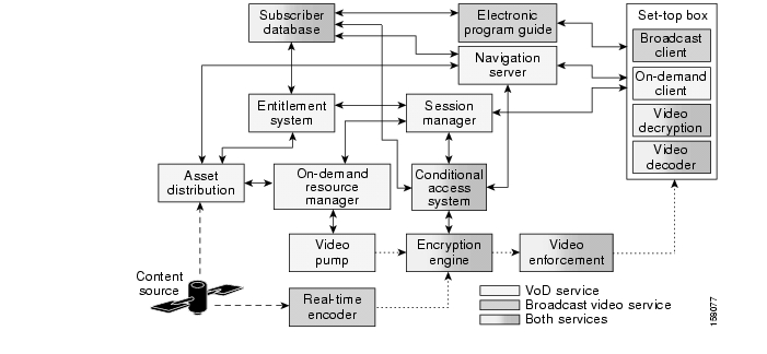
Figure 2-1 illustrates the logical relationship of the application-layer video components needed to deliver broadcast video and VoD services, as well as the basic interfaces between components. Components can be categorized as follows:
•
Figure 2-1 Video Application Component Architecture
Broadcast Video Components
Broadcast video components (see Figure 2-1) include the following:
These are described below.
Real-Time Encoder
The real-time encoder takes a live feed from a broadcaster in either analog or digital format and converts it into a compressed digital stream that is encapsulated in IP packets. The input to the encoder may be in a digital format that uses MPEG-2 over synchronous media such as ASI, or it may be in an NTSC, PAL, SECAM, or other analog format. The output of the encoder is a digitally compressed stream that is encapsulated in IP headers and sent to a multicast address. The compression method used by the encoder may be either MPEG-2 or MPEG-4, while the IP-based transport encapsulation used is MPEG-2 transport over either UDP/IP or IP/UDP/RTP. because the real-timer encoder is configured to encode a specific channel, no control interfaces are required between it and other video components.
Electronic Program Guide
The electronic program guide (EPG) provides information about available broadcast channels to the broadcast client application running on the IP set-top box (STB). The EPG is often implemented as an HTTP server and formats available channel listings as web pages. The EPG application authenticates and authorizes a subscriber for broadcast services. The EPG may also provide a customized view of channel listings that is based on the packages a particular subscriber has subscribed to. Both of these functions require an interface between the EPG application and the subscriber database. In addition to providing a graphical listing of available channels, the EPG provides the IP multicast address to which the channel is sent in the IP network. The broadcast client uses this address in Internet Group Management Protocol (IGMP) messages that are sent during the processing of a channel change.
Broadcast Client
The broadcast client is an application process running on the STB that is responsible for providing the user and control interface for broadcast video services. The broadcast client, in conjunction with the EPG, implements a subscriber authentication interface for set-top-based services. Authentication is typically done by means of an application layer authentication protocol such as HTTP in conjunction with a shared secret such as a username/PIN pair.
The broadcast client displays available broadcast-channel information using data from the EPG and implements the control interface for channel change by means of IGMP. Since the DSL line may be capable of supporting the bandwidth of only a single broadcast channel, the IGMP process for changing channels must ensure that only a single video broadcast stream is sent to the STB at a time. The broadcast client implements this by sending an IGMP leave for the current channel and then waiting for a configurable period of time for the broadcast stream to stop. After this timer expires, the broadcast client sends an IGMP join for the new channel. The full channel-change time, documented in Broadcast Video Channel-Change Time, includes these IGMP factors as well as other factors specific to video compression. (See also Effect of Multicast on Channel-Change Performance.)
Note
VoD Components
VoD components (see Figure 2-1) include the following:
These are described below.
Asset Distribution System
The asset distribution system (ADS) takes video content from content providers and uses business rules to distribute that content to different locations in the video service provider's network. Video content may be provided to the ADS through a number of different methods. These methods include the use of pitcher/catcher systems, which receive video content from content providers over satellite links, and manual processes such as file copies from other network servers.
Standard video content objects include the actual MPEG video, images for display during content navigation, trailers, and metadata files that provide information about the files contained in the object. Metadata files often follow a standards-based format specified in the CableLabs Asset Distribution Specification.
The ADS may be used to modify the metadata of a video asset to add business rules such as the price of the video, the distribution window, the VoD subscription package that the video is part of, whether the content needed to be encrypted, and so on. On the basis of these business rules, the ADS replicates the video asset to the on-demand resource management component of video servers in different locations.
Navigation Server
The navigation server provides information about available VoD content to the on-demand client application running on the STB. The navigation server is often implemented as an HTTP server and formats available VoD content as web pages. The navigation server uses information provided by the asset management system to determine which VoD content to display to the subscriber. For subscription-based VoD services, the navigation server may use the information in the subscriber database to customize the view of the video content presented to the subscriber, depending on the packages the subscriber has purchased.
Session Manager
The session manager is the central point of communication for VoD session requests that originate from the on-demand client on the STB. It manages the life cycle of a video session and is responsible for arbitrating the various resources required to deliver the video stream associated with the on-demand session request. Many vendors of VoD equipment and software provide a logical "session manager" function, though this function goes by a variety of different names.
When the session manager receives an on-demand session request from an on-demand client application, it first uses the services of the entitlement system to determine whether the subscriber is authorized to view the requested video content. If the request is authorized, the entitlement server includes additional information in the authorization response, such as the encryption format to be used for the content.
When the session manager receives the authorization response, it determines the best VoD server complex to use for the session request, based on the subscriber's IP subnet. The session manager then contacts the on-demand resource manager for that VoD server complex to request a video pump for the session. If the VoD content needs to be encrypted in real time, the session manager contacts the conditional access system (CAS) to request a real-time encryption engine for the session. The CAS responds with the decryption keys to be used by the STB to decrypt the video stream.
After all of the resources for a VoD session request are obtained, the session manager responds to the on-demand client with information about the IP/UDP/RTP transport parameters for the video stream to the STB. If the stream is to be encrypted, the session manager (or a key manager with which it coordinates) includes the decryption keys for encrypted video content in the response as well. Finally, the session manager includes the IP address of the video pump that was selected for the session. The IP address of the VoD pump is needed by the on-demand client in order to send stream control requests through Real Time Streaming Protocol (RTSP)—such as pause, fast forward, rewind—for the session.
Entitlement System
The entitlement system is responsible for determining whether the movie requested by an on-demand client is authorized for viewing by the subscriber associated with that client. The entitlement system uses information from the ADS to build a database indicating which videos are associated with different on-demand subscription packages. When the entitlement system receives an entitlement request from the session manager, it uses this database to determine with which orderable on-demand package the requested video is associated. The entitlement system then uses the services of the subscriber database to determine whether the subscriber associated with the entitlement request is entitled to view the requested video.
Video Pump
The video pump is the streaming storage component of a VoD system. The video pump contains locally or remotely connected storage that is organized in such as way that it can send any piece of stored media at a known constant rate. The streaming portion of the video pump is responsible for pulling requested files from the storage system and for pacing the output of each requested file to the network though the use of a shaper. Video pumps must be capable of implementing basic stream control functionality, such as fast-forward and rewind, to respond to requests from the on-demand client during the playout of a media file.
In addition to being able to stream media out, video pumps are also responsible for ingesting media for storage in the storage subsystem. While in general the functionality of a video pump is fairly independent of media format, the ingest function may have functionality that is specific to a particular media format. An example of this type of media-format dependence is the generation of trick files for use with stream control functionality such as fast-forward and rewind. Video pumps used in broadband environments are typically capable of storing and streaming both MPEG-2 and MPEG-4 content.
On-Demand Resource Manager
The on-demand resource manager (ODRM) is responsible for managing the streaming resources and storage of a group of video pumps. The ODRM is responsible for locating and replicating content, as well as for allocating video pumps for the on-demand session requests it receives from the session manager.
On the ingest side, the ODRM is responsible for taking content received from an asset management system and replicating it to one or more of the video pumps it controls. The ODRM makes decisions on when and where to replicate content on the basis of such information as asset metadata and the demand for each title (as indicated by on-demand session requests).
On the streaming side, the ODRM responds to on-demand session requests from a session manager by locating a video pump that contains the requested title, has the capacity to stream the title, and is capable of reaching over the transport network the subscriber that generated the session request.
On-Demand Client
The on-demand client (ODC), an application process running on the STB, is responsible for providing the user and control interface for on-demand services. The ODC provides the user interface for browsing on-demand content using the services of the navigation server. The browsing interface of the ODC is typically implemented by means of an embedded HTTP-based browsing application.
The ODC interfaces to the session manager to make requests to stream on-demand content. It also interfaces to video pumps to make stream-control requests for movies that are actively being streamed.
Common Broadcast Video and VoD Components
Common broadcast video and VoD components (see Figure 2-1) include the following:
•
•
•
These are described below.
Conditional Access System and Encryption Engine
The conditional access system (CAS) is responsible for the key management and distribution infrastructure associated with the encryption of video content. Video encryption is used as the second tier of protection against theft of content. The first tier of protection for both broadcast and on-demand services is performed as part of the on-demand and broadcast client applications running on the STB. These applications use the services of the EPG and navigation server to authenticate the subscriber and provide a customized view of available channels and content based on the services the subscriber has purchased. For on-demand services, the entitlement system also checks whether the subscriber is authorized to view requested titles, with the result that the ODC does not allow the subscriber to view unauthorized content. While application-layer authorization protects against the theft of content from authorized STBs, it does not protect the video stream itself. Video encryption using CAS provides this second layer of protection against theft and unauthorized viewing of video content.
Because conditional access adds an additional level of complexity and cost to a video delivery system, service providers typically use CAS-based encryption only on premium-tier broadcast channels and on-demand titles. For broadcast services, encryption must be done in real time as the video stream is delivered. For on-demand services, encryption may be done either in real time as the content is streamed or as part of the process of replicating content to video pumps. The process of encrypting video content as part of replication is called pre-encryption.
Video encryption may be done on either a tier or session basis. In tier-based video encryption, a single set of encryption/decryption keys is used for all of the video content associated with a particular service offering. Subscribers that are authorized to view the content associated with the service are delivered the decryption keys needed for that service ahead of time. Conditional access for broadcast video services is always implemented by means of tier-based encryption, because a single video stream may be viewed by many subscribers simultaneously. Decryption keys for broadcast video services are delivered in a secure manner to the STB through the EPG. In session-based video encryption, decryption keys for a piece of content are generated and delivered to the subscriber on a per-session basis. Session-based encryption may be used with VoD content. Because decryption keys are generated only on a per-session basis for session-based encryption, they may be used with either real-time or pre-encryption techniques.
In a typical CAS, the encryption of digital services can be achieved by using entitlement control messages (ECMs) and entitlement management messages (EMMs). In order to generate the final keys needed to decrypt a particular video stream, the STB must receive and decrypt the correct ECMs and EMMs. EMMs provide keys that can be decrypted only by a specific subscriber, while ECMs provide keys that are specific to a particular video stream. Because EMMs are specific to a subscriber, they are always generated ahead of time. Because ECMs are specific to a particular video stream, they may be generated ahead of time when pre-encryption is used, or they may be generated in real time when real-time encryption is used. ECMs are typically delivered in band as a component of the video stream.
Whether the content must be encrypted may be determined by a number of factors. For on-demand services, content providers can require content to be encrypted by enabling the "Encryption" field in the metadata file associated with the video asset. For broadcast services, the video service provider statically configures the video stream from real-timer encoders to be sent either directly to a multicast group or to a real-time encryption engine, depending on whether that channel is to be encrypted.
The encryption engine takes MPEG streams in and encrypts them in real time using encryption keys received from the CAS. Encryption engines typically use a DES algorithm for encryption.
Broadcast Video Bandwidth Enforcement
Broadcast video bandwidth enforcement is implemented as part of the functionality of the provider-edge aggregation router (AR) (sometimes referred to as the PE-Agg router). The AR enforces a maximum broadcast bandwidth limit by limiting the number of IGMP joins on the ranges of multicast addresses associated with broadcast video to a configured maximum on the aggregation links it controls. The mapping of video channels to multicast addresses can be done in such a way that the AR can associate the bandwidth for different classes of video (for example, standard definition or high definition) with different ranges of multicast addresses. IGMP join limits can then be set for each range of multicast addresses.
For more details on the network enforcement for video broadcast, refer to Multicast Admission Control.
Set-Top-Based Video Decryption and Video Decoder
The set-top box, or STB (see below), includes two components that are responsible for turning the incoming video stream, delivered as IP packets, into an uncompressed digital stream that can be directly turned into an analog TV signal ready for display by a television set. These components are the video decoder and the video decryptor.
The video decoder is responsible for decompressing the incoming video stream. It uses a decompression algorithm that is matched to the compression algorithm used by the real-time encoders for broadcast services. The video decoder may also support additional decompression algorithms for VoD services if VoD assets are compressed by a different algorithm than broadcast channels use.
The video decryptor is responsible for performing decryption on the video stream if the stream was encrypted by the encryption engine when real-time encryption is used, or by an offline encryptor when pre-encryption is used for on-demand assets.
Set-Top Box
The set-top box (STB) is the hardware and common software infrastructure component that is used by the on-demand and broadcast clients as well as by the video decryptor and the video decoder. The STB hardware typically consists of a general-purpose processor and video subsystem that produces an analog television output. The hardware may also include a hardware-based decoder and decryption subsystem. The STB software typically includes an embedded operating system, and may also include application infrastructure components such as a web browser.
The subscriber database contains service level information about each subscriber—for example, the services the subscriber is authorized to use, billing information, and so on. The subscriber database may also contain information that can be used for subscriber authentication. An example of this type of information is the username and password used by the EPG to identify and authenticate a subscriber for broadcast services.
Subscriber Database
The subscriber database contains service-level information about each subscriber, for example, which services the subscriber is authorized to use, information used for billing, and so on. The subscriber database may also contain information that can be used for subscriber authentication. An example of this type of information is the username/password information that is used by the EPG to identify and authenticate a subscriber for broadcast services.
Video Application Product Architecture
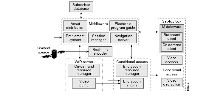
This section describes how the logical components described previously are commonly combined into products that are supplied by current video-component vendors. Figure 2-2 illustrates how the video components presented in Figure 2-1 are "bundled" into application products. This bundling reduces the number of products and vendors that must be integrated to build a complete video system. It also reduces the number of interfaces that must be agreed upon by vendors.
Figure 2-2 Common Video Application Product Architecture
Note
The following classes of video products are needed to build a complete broadband video solution:
•
These are described below.
Middleware
Middleware, as defined, has the role of gluing a number of logical components together into a more comprehensive IPTV/video software system. (Note that there are several different middleware implementations. Thus, the following description is a typical example for illustrative purposes.) Middleware implements the user interface for both broadcast and on-demand services. It is also used as the glue software that integrates products from other vendors into an application level solution. Middleware products are often used to integrate multiple VoD servers, conditional access systems, and set-top boxes from different vendors into the same deployment.
Middleware provides the client and server functionality that implements the user interface for both broadcast and on-demand services. The components that provide the client-side functionality are the broadcast and on-demand client applications on the STB, while the components that provide the server-side functionality are the electronic program guide and the navigation server.
Middleware uses the entitlement system and session manager components to integrate the VoD servers used in an on-demand service. The entitlement system integrates the asset ingest function of a VoD server, while the session manager integrates the session plane of the VoD server into an on-demand service.
Middleware uses the session manager and on-demand client to integrate CAS into an on-demand service. These components may be used to pass decryption keys from the conditional access system to the video decryption component in the STB. These components also determine when to use the services of the CAS based on the encryption requirements of the service and each asset associated with the service. Middleware uses the EPG and the broadcast client to integrate CAS into a broadcast service. The broadcast client determines when to use the services of the CAS based on information it obtains from the EPG on each broadcast channel.
VoD Server
The VoD server (one or several) implements storage and real-time streaming functionality for on-demand services. The VoD server consists of a set of video pumps that are managed by an on-demand resource manager. The VoD server integrates with middleware and may also be integrated with the CAS when preencryption is used.
Conditional Access System
The conditional access system (CAS) provides encryption and decryption services, as well as key generation and distribution functionality, for both broadcast and on-demand services. The CAS consists of the encryption resource manager, the encryption engine, and the video decryption process in the STB.
The CAS interfaces to middleware when session-based encryption is used for on-demand services. The CAS may also interface to middleware for encryption key distribution between the encryption resource manager and the decryption process on the STB. Finally, the CAS interfaces to VoD servers where preencryption is used for on-demand content.
Real-Time Encoder and Set-Top Box
The real-time encoder and STB components described in Real-Time Encoder, and Set-Top Box, respectively, are identical to product classes of the same name shown in Figure 2-2.
Video Transport Architecture and Issues
To meet the end-to-end transport requirements for broadcast VoD services, the wireline video/IPTV transport architecture provides functional requirements and configuration recommendations for each switching node in the path from the VoD servers to the STBs. This section presents the following topics:
•
•
Note
Video Sites
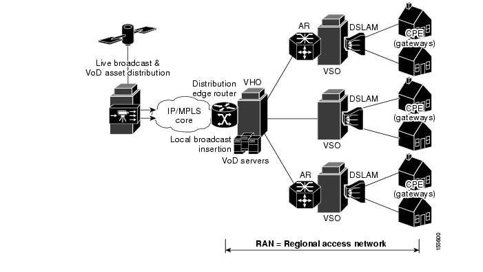
The video sites described in this section are the super headend (SHE), the video headend office (VHO), and the video switching office (VSO). Figure 1-1 shows the location and roles of the sites and components in a typical IPTV/VoBB deployment.
Super Headend
The SHE is where live feeds for the broadcast video service are located. This site contains the real-time encoders used for the broadcast video service, along with the asset distribution systems for on-demand services. This site may also contain back-office systems such as the subscriber database. Most wireline video/IPTV deployments have a single SHE site; this is the source of most of the multicast streams for the broadcast video service. The SHE typically resides in the core of the transport network.
Video Headend Office
The manned VHO is where the video server complex resides (as well as where optional local/PEG content may be inserted). The VHO is where the majority of the video pumps used for on-demand services are typically located. It is also where the real-time encoders for local television stations reside. A VHO typically serves a metropolitan area of between 100,000 and 1,000,000 homes. The VHO is equivalent to (and may be contained in) the same facility as the point of presence (POP) for Internet access services. Transport for video traffic between the VHO and IP/MPLS core network is provided by a distribution edge router (DER). The DER interconnects the core network and the local video sources to a high-bandwidth distribution network that carries both broadcast and on-demand video to VSOs.
Video Switching Office
The VSOs house the aggregation routers that aggregate local or remotely attached GE DSLAMs. The VSO is typically located in the central switching office. The central switching office is the physical termination point for the majority of the copper loops for the residences it serves. Because ADSL and ADSL2+ rely on short loop lengths to obtain maximum training rates and throughput, the copper loops used for DSL service are often terminated at a location closer to the subscriber than the VSO. This means that the DSLAMs that the VSO aggregates may or may not be colocated in the VSO. The switching equipment in the VSO interconnects the aggregation and distribution networks. Traffic to and from the DSLAMs is aggregated by the aggregation router (AR).1 The AR resides in intermediate and terminal VSOs.
In order to minimize the bandwidth requirements between the VSO and the VHO, a VSO may include local video pumps that are used to cache popular on-demand content. While the Release 1.1 transport architecture does not preclude the use of video pumps in the VSO, this configuration is not tested as part of the solution test effort.
Figure 2-3 presents an overview of the solution transport architecture
Figure 2-3 Solution Transport Architecture: Overview
Video Service Requirements
In order to understand better some of the design tradeoffs associated with the transport architecture, it is important to understand common requirements for a video service and how an IP network can be optimized to meet these requirements. This section outlines some common requirements for broadcast video and VoD services. It also describes what design factors in the transport network are relevant to these requirements.
High Bandwidth
The amount of bandwidth that a network must be capable of transporting to support video services is typically an order of magnitude more than what is required to support voice and Internet access services. A standard-definition IP video stream that is carried as an MPEG-2 SPTS stream over RTP uses about 3.75 Mbps of bandwidth. A high-definition IP video stream using the same type of compression and transport uses about 15 Mbps of bandwidth.
These bandwidth requirements mean that a DSL access infrastructure that is designed for real-time video transport must be capable of carrying significantly more bandwidth than what is needed for VoIP and Internet access services. It also means that the DSL line itself is typically constrained to carrying only one or two video streams simultaneously. The result is that video over DSL service offerings must limit the service to one or two simultaneous broadcast channels or on-demand sessions to a household.
Because the video streams associated with on-demand services are unicast while the video streams associated with broadcast services are multicast, the amount of bandwidth required in the aggregation and distribution networks to carry on-demand streams is much greater than what is required for broadcast services. Also, because broadcast video services use multicast, the amount of bandwidth required in the access and distribution networks scales with the number of channels offered. As an example, a broadcast video service that uses MPEG-2 compression and offers 300 channels of standard-definition content requires approximately 1 Gbps/sec of capacity in the distribution network to handle worst-case usage patterns. Because on-demand services use unicast transport, the amount of bandwidth required in the distribution network scales with the number of subscribers and peak on-demand utilization rates the network is designed to carry. For example, a distribution network that is designed to deliver MPEG-2 compressed standard-definition content to 50,000 on-demand subscribers at a 10% peak take rate requires about 19 Gbps of capacity.
Asymmetric Bandwidth
Video traffic is inherently asymmetric, as both broadcast video and VoD flows are unidirectional. The only traffic that is sent in the upstream direction of either service is control traffic that is used to instantiate the video flow. For on-demand services, this control traffic is the session and resource signaling that is described as part of the component descriptions in Video Application Components. For broadcast services, the control traffic is IGMP and PIM signaling that is used to instantiate the multicast flow for the broadcast channel.
Because of this asymmetry, the cost of the distribution network can be reduced by incorporating unidirectional links in the transport path. One of the transport alternatives tested in the previous release of the solution included unidirectional transport in the distribution network.
Note
Quality of Service
When broadcast and on-demand video is carried over an IP network, there is an assumption that the video quality is not degraded when compared to other digital video transport alternatives, such as MPEG-2 directly over a QAM modulation carrier used in both cable and satellite networks today. To ensure that any degradation in video quality due to the IP transport network is negligible from a subscriber's point of view, most carriers allow the transport network to introduce at most one visible degradation in video quality about every two hours.
While this end-user requirement is similar to what is currently accepted for voice over IP (VoIP) services, the resulting allowed drop requirement for an IP transport network designed for video services is much more stringent than the requirement for VoIP. The reason for the difference in drop requirements between VoIP and video can be attributed to how video and voice are processed by video STBs and VoIP phones and gateways. VoIP phones and gateways typically support algorithms that are designed to conceal dropouts in the voice signal caused by lost packets in the IP network. The result is that the IP network can drop a single voice packet without the listener noticing any degradation in voice quality. Because of the compression algorithms used, and the amount of information carried in a single video over IP packet, current-generation STBs do not support concealment algorithms such as those used for VoIP services. The result is that when the IP transport network drops a single video packet, there is a visible degradation of video quality of anywhere from a single frame up to one second, depending on the information that is lost.
Assuming a random loss pattern for video and voice packets, the resulting allowed drop rates for video and voice services are 10-6 and 10-2, respectively. The lower allowed drop rate for video means that both drops caused by congestion and drops caused by bit errors on physical links must be taken into account when one designs a transport network for video services.
The DiffServ architecture defines packet marking and scheduling behaviors that can be used to ensure that video flows meet the required 10-6 drop rate when links are congested. ( QoS Architecture, provides details on the QoS architecture for the solution.)
Packet drops due to bit errors on physical links need to be addressed on a link-by-link basis. Note that the link-layer technologies used in video networks use cyclic redundancy check (CRC) algorithms to ensure that packets with errors are not delivered. This means that a single bit error in a video packet results in that packet being dropped when the CRC is performed. Video over IP is typically carried in packets that are approximately 1400 bytes. If bit errors are assumed to be distributed randomly, the resulting requirement for transport links is to ensure a bit error rate (BER) of less than 10-10.
The BER on optical links can be engineered to 10-14 or less by ensuring a high signal-to-noise ratio (SNR) on those links. Because Release 1.1 of the solution uses optical connectivity in the access and distribution networks, the degradation in video quality resulting from bit errors on these links should not be an issue.
However, packet drops due to bit errors on the DSL line can have a significant effect on video quality. The SNR on a DSL line varies as a result of many factors, including loop length, proximity to noise sources, and so on. In addition, the SNR may vary over time because of factors such as corrosion at connection points, moisture, and so on. Consequently, it may be very difficult to qualify a DSL line to ensure a BER of less than 10-10 at the time of installation.
Multiple technologies are available to deal with bit errors on the DSL line. Some common technologies are DSL-based forward error correction (FEC) interleaving, and real-time retransmission (RTR). While the Release 1.1 of the solution does not include the testing of these technologies, future versions of the solution will include technologies to deal with bit errors on the DSL line.
DSL-based forward error correction (FEC) and interleaving is a standards-based method of improving the bit error characteristics on the DSL line by including additional error correction information in the DSL bit stream. The error correction information and data are interleaved to make the DSL bit stream more resilient to instantaneous line hits. While this technology improves the resilience of the DSL line with respect to bit errors, it significantly increases the transmission delay for packets sent over the line. This increased transmission delay does not affect video services. However, it may have a significant impact on highly interactive services such as network-based gaming applications. Because of the above factors, DSL-based FEC and interleaving may not be the best technology for improving loss characteristics resulting from bit errors on the DSL line.
RTR is an IP transport-layer function that enables the transport stack on an STB to provide feedback to a video transmitter when a video packet is dropped by the network. If the transmitter can resend the dropped packet to the STB before that packet's playout time, then the STB can insert the resent packet into the jitter buffer and continue processing as if the packet were never lost. Because the jitter buffer of most IP STBs is around 200 msec, RTR methods work if the whole retransmission process takes less than 200 msec. An example transport standard that implements RTR is the RTP retransmission standard specified in the AVT Working Group of IETF. RTP retransmission supports the real-time retransmission of both unicast and multicast streams, so it is applicable to both VoD and broadcast video services.
RTR has a couple of advantages over DSL FEC and interleaving for video and other services. Because RTR is a transport layer function, it can be enabled for only the video service where low loss rates are required. RTR also does not cause any additional delay to either video or interactive applications. RTR can be used to make up for loss anywhere in the path between the transmitter and the STB. Finally, RTR does not result in increased bandwidth when the path between the transmitter and the STB are not experiencing loss. The down side of RTR is the fact that it requires application support in both the STB and the transmitter. In addition, RTR schemes experience performance problems as the round trip time (RTT) between the STB and the RTR-enabled transmitter increases and as the number of STBs served by an RTR-enabled multicast transmitter increases.
Service Availability
Service providers deploying video services often have different availability requirements for VoD and broadcast video services, as contrasted below.
Broadcast video services are inherently real time. A subscriber who experiences an outage in the broadcast service cannot come back and continue watching at that point when the outage is over. Because of this and the higher usage rates associated with broadcast services, the availability associated with broadcast services must be very high.
In contrast, the customer disruptions associated with an outage in VoD services are typically much less problematic. A subscriber who experiences an outage in a VoD service can come back at a later time and replay the content—either from the point of disruption or from the beginning. In addition, the peak usage rates associated with VoD are typically between 10 and 20% of the subscriber population. This is much lower than the peak usage rates for broadcast services.
Because of the above factors, service providers have much higher availability requirements for broadcast services than for on-demand services. Consequently, the differing availability requirements between the two services may result in differing transport requirements for each service. For example, the high-availability requirement for broadcast video typically results in the requirement that there be redundant transport paths between the DER and AR nodes of the distribution network. (See Figure 2-3.) Because of the higher bandwidth and lower availability requirements associated with VoD services, the topologies used for these services may not necessarily require redundant transport paths.
The service-mapping architecture documented in Release 1.0 of the solution enables distribution network designs that provide path redundancy for both services, as well as a cost-optimized distribution design that provides path redundancy for broadcast services only. (While Release 1.1 of the solution does not include network designs that offer different levels of path redundancy for different services, Release 1.0 does.) In addition, the quality of service (QoS) architecture includes DiffServ marking for broadcast and on-demand services, allowing the network to drop VoD traffic preferentially over broadcast traffic in the event of a network outage. Finally, the solution supports redundant broadcast video encoders, as well as a method to fail over in a timely manner from one encoder to another. Both of these features are included in the network designs illustrated and tested in this release of the solution.
Broadcast Video Channel-Change Time
An important aspect of a broadcast video service is the amount of time it takes for the system to respond to a channel-change request from a subscriber. While the channel-change time for current analog broadcast services is perceived by the subscriber to be instantaneous, the channel-change time for digital broadcast services is between one and one-and-a-half seconds. The majority of this time is due to the differential encoding and decoding methods used to compress digital video streams.
To reduce the amount of bandwidth required for digital video transmission, compression methods such as MPEG compress the video frames of a digital video stream into three different types of frames. These frames are called I-frames, B-frames, and P-frames. An I-frame is a compressed version of all of the information in one frame of a video stream. An MPEG decompressor can recreate the original frame using just the information in the I-frame. A P-frame is an incrementally encoded video frame that can be decoded with the information in the preceding anchor frame (I-frame or P-frame). A B-frame is an incrementally encoded video frame that can be decoded with the information in the preceding and following anchor frames (I-frame or P-frame).
Because of incremental coding, an important factor in how long it takes to change a channel for a digital video service is the I-frame gap. The I-frame gap defines how often I-frames are included in the MPEG stream. Shorter I-frame gaps result in shorter channel-change times, while longer I-frame gaps result in longer channel-change times.
When a digital broadcast service is run over a DSL access infrastructure, the following additional factors must be added to the delay caused by the I-frame gap:
•
•
•
•
•
•
The goal of this solution is to provide subscribers with a channel-change experience similar to that currently experienced for digital broadcast services. Most of the additional channel-change delay associated with a DSL access infrastructure is due to the amount of time it takes for the network to stop sending the multicast stream for the "tuned from" channel and to begin sending the multicast stream for the "tuned to" channel. Multicast Admission Control, provides a recommendation for a scalable multicast architecture that best meets the channel-change requirements for broadcast video services.
Potential Video Service Architectures
One aspect of a transport architecture for video that must be considered initially is how the service provider sells the video service to the subscriber. This section examines how two potential video service-level agreement (SLA) models affect the requirements of a transport network implemented to deliver the service to the subscriber.
•
•
–
–
–
The services the network provides to deliver a transport-based SLA as opposed to an application-based SLA are very different. Table 2-1 provides an overview of the technologies used to deliver the basic functionality of a transport service as opposed to an application service.
Table 2-1 Service-Delivery Technologies: Transport vs. Application
SLA
Transport parameters:
•
•
•
•
Video application SLA:
•
•
Subscriber authentication/
identificationNetwork based (examples):
•
•
•
•
•
Application based:
•
SLA enforcement
Network based:
•
Application based:
•
QoS
Per subscriber:
•
•
•
Aggregate:
•
1 Dynamic Host Control Protocol
2 Point-to-Point Protocol over Ethernet
The two SLA models are examined in detail in the following sections:
•
•
Network Requirements for Transport Services
Subscriber authentication and identification for a transport service is done at the transport layer. Subscriber authentication technologies rely on shared secrets such as passwords or private/public key pairs to establish a trust relationship between the subscriber and the network. Subscriber identification technologies use a well-known property of a subscriber (such as the DSL line to which the subscriber is attached) to identify all packets coming from or to the subscriber. Transport SLA enforcement requires a subscriber identification technology and may also include a subscriber authentication technology.
Common subscriber-authentication technologies used for a transport service include Challenge Handshake Authentication Protocol (CHAP) used with Point-to-Point Protocol over Ethernet (PPPoE) and Dynamic Host Control Protocol (DHCP)-based authentication used with native IP. These technologies are used to authenticate a subscriber transport session. To enforce a subscriber's transport SLA at the transport layer in PPPoE environments, every packet associated with a subscriber's transport session can be identified with a PPPoE session ID that is specified as part of the PPPoE tunnel encapsulation. In native IP environments, every packet associated with a subscriber's transport session can be identified by using the IP source/MAC address of the packet. Note that both PPPoE-based and native IP-based architectures could also use a VLAN tag to identify the traffic associated with a particular transport session. Either VLAN tags or DHCP option 82 could be used to associate a transport session with an access line such as a DSL line. Note also that an identification technology could be used to enforce a subscriber transport SLA without the use of an explicit subscriber-authentication protocol.
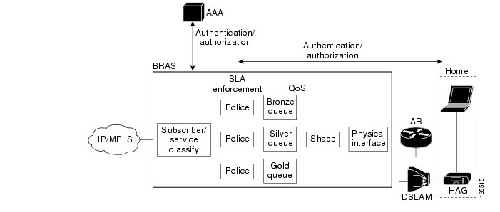
SLA enforcement and the resulting QoS architecture used for transport services rely on per-subscriber shaping, as well as on per-subscriber, per-service classification, policing, queueing, and scheduling. SLA enforcement is typically implemented in the same node that terminates the transport session (PPPoE or DHCP). Packets are classified per subscriber according to the transport session identifiers described above. The downstream traffic for each subscriber is typically shaped to a maximum rate based on the parameters of the transport SLA. If the transport SLA sold to the subscriber includes more than one class of service (gold, silver, or bronze), then additional classification, queuing, and scheduling are done to enforce and guarantee the transport parameters of the SLA associated with each class. For transport services, the node that terminates the transport session and enforces the subscriber SLA is typically the broadband remote-access server (BRAS). Figure 2-4 illustrates the per-subscriber control and data plane functionality used by the network to implement a transport service.
Figure 2-4 Per-Subscriber Control and Data-Plane Functionality Used to Implement a Transport Service
Network Requirements for Managed Application Services
Subscriber authentication for an application service is implemented by means of application-aware components. For example, Electronic Program Guide, describes how subscriber authentication for a video service is typically implemented as part of the electronic program guide (EPG) function. The EPG, a component of video middleware, often authenticates a subscriber's video STB by means of an application-layer challenge such as an HTTP authentication challenge. If the EPG is not able to authenticate the STB, the subscriber cannot use the STB for broadcast video services. SLA enforcement for a managed application service is also performed by application-aware components. As an example, the number of simultaneous video streams that a subscriber may have active for a video application service is limited by a combination of (1) the number of authorized STBs the subscriber has in the home, and (2) the video session limits enforced by the video middleware.
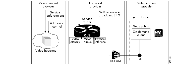
Because SLA enforcement for a managed application service is performed by application-aware components, the QoS architecture required to support an application-aware service can be greatly simplified. Instead of having shapers and queues per subscriber, QoS architectures that use class-based classification and scheduling, such as the DiffServ architecture, can be used for QoS. Figure 2-5 illustrates the application and transport architecture used to implement a video application service.
Figure 2-5 Application and Transport Architecture Used to Implement a Video Application Service
While an Internet access service is typically sold as a transport service, a video service may be sold to a subscriber as ether a transport or an application service. From the discussion above, the transport architecture needed for an application service is significantly different from that needed for an application service.
The Release 1.1 transport architecture is optimized for service providers that sell video as a managed application service. In the solution transport network design, architectural tradeoffs have been made with this assumption in mind.
Service Mapping in a Triple-Play Architecture
An important aspect of the transport network for a triple-play architecture is how much support the network provides in isolating each service. This section addresses the following topics:
•
•
•
Minimally, the network must provide the ability to meet the delay and drop requirements for each service when multiple services share the same physical link. This capability is inherent in the QoS architecture of the solution. (See QoS Architecture.)
In addition, the network may be configured to provide separate forwarding and routing domains for each service. This level of service mapping is very useful when a service provider wants to manage separately the address space, topology, and IP infrastructure associated with each service. The following subsections explain why a service provider may want to have different transport attributes for different sets of services.
Forwarding Architectures
The transport architecture associated with different services may require the use of different encapsulations and therefore different types of packet forwarding. If one creates separate logical topologies for different services, these services can be forwarded by means of different forwarding techniques. The paragraphs below illustrate how the different transport architectures of Internet access and video services require that there be separate logical forwarding planes for the two service categories.
As explained in Potential Video Service Architectures, Internet access service is typically sold as a transport service. In a DSL environment, this typically results in a transport architecture that uses a PPPoE session from a CPE device to a BRAS that authenticates subscriber sessions and enforces the SLA associated with that session. Because PPPoE encapsulation requires an 802.3 header, PPPoE packets must be forwarded by means of Layer 2 switching between the PPPoE client (the CPE device) and the PPPoE server (the BRAS).
Also from Potential Video Service Architectures, the transport architecture in the solution assumes that the SLA for video services is an application SLA. Because authentication and enforcement are application services implemented in application components, there is no need to use a Layer 2 tunneling protocol such as PPPoE or a transport-layer authentication and enforcement component such as a BRAS for video services. Instead, video services can use IP encapsulation between the STB and the video infrastructure components described in Video Application Components. Since IP encapsulation is used, there is no need to forward packets between STBs and the video infrastructure components in the VHO using only Layer 2 switching. The solution transport architecture described in this document uses a combination of Layer 2 and Layer 3 forwarding for broadcast video and VoD services.
Note that the Internet access transport architecture described above requires that the access, aggregation, and distribution networks switch Internet access packets at Layer 2, while the video transport architecture allows these networks to switch video packets at either Layer 2 or Layer 3. To allow Layer 3 switching for video and Layer 2 switching for Internet access, the network must be configured into separate logical topologies that are switched by means of different encapsulations and packet switching functions (Layer 2 vs. Layer 3). In the two configuration models presented in this design and implementation guide (see Release 1.1 Configurations), the transport architecture separates these logical topologies as follows:
•
•
Service-Availability and Bandwidth Requirements
Because different services have different service-availability and bandwidth requirements, a service provider could potentially reduce the cost of the network while maintaining the requirements for each service by creating separate logical topologies for different services.
As an example of different service availability requirements, Service Availability, describes the different availability and bandwidth requirements of broadcast video and VoD services. A service provider could optimize the network for both services by creating separate logical topologies for each service. These topologies could be created by using VRF-based technologies such as MPLS VPN or VRF-lite. [VRF stands for virtual private network (VPN) routing and forwarding, as well as a VRF instance.] In addition, the separate logical topologies could be created by populating the routing table with multiple instances of routing processes running on the different topologies and not exchanging routes between these processes. The differing availability requirements for broadcast video and VoD may lead to a transport requirement that the network must provide redundant paths for broadcast video but not for VoD. To meet this requirement cost-effectively, separate logical topologies can be created for the two services. The logical topology for broadcast video maps the address space associated with real-time encoders and STBs into a topology with redundant physical paths, while the address space associated with VoD servers and STBs maps into a VRF with nonredundant physical paths.
Note
Organizational Structure
A service provider may have an organizational structure in which different services are managed by different organizations. The ability to map different services to different logical topologies allows each organization to manage and debug the transport as well as the IP infrastructure components separately.
IP Infrastructure Components
When different services are managed by different organizations within a service provider, it may be operationally simpler to have separate IP infrastructure components such as Dynamic Host Configuration Protocol (DHCP) servers for different services. Using different DHCP servers for different services allows the IP address spaces for these services to be managed separately. It also allows the DHCP servers to be configured separately for different services without having to use static configuration on the DHCP server to associate different CPE devices with different services.
Service Mapping in the Release 1.1 Architecture
Because of the transport architecture issues described in Forwarding Architectures, it is unlikely that early wireline video/IPTV deployments use a unified transport architecture for all services. Because of this, Release 1.1 uses a service mapping architecture in which traffic associated with each service is forwarded to or received from a separate logical access topology at the CPE device. This service-based logical topology separation is continued through the aggregation and distribution networks.
This transport architecture allows traffic associated with different services to be aggregated or terminated at different sites by means of different infrastructure components. This architecture allows traffic associated with Internet access services to be aggregated at a BRAS, while traffic associated with video services (specifically the managed video application service types) is terminated by means of the video infrastructure components described in Video Transport Architecture and Issues.
Video Forwarding Architecture, describes how service mapping is implemented in the aggregation and distribution networks in Release 1.1, while Edge Transport Architecture, describes alternatives for implementing service mapping at the CPE device and in the access network.
Triple-Play Architecture—Relation to Existing Standards
The DSL Forum publishes specifications for DSL-based access and aggregation transport architectures. The TR-25 and TR-59 specifications currently published by the DSL Forum specify the access and aggregation infrastructure requirements and architectural alternatives for an ATM-based DSL aggregation infrastructure. The DSL Forum is currently finalizing a new specification, labeled WT-101, that specifies the access and aggregation infrastructure requirements and architectural alternatives for an Ethernet-based DSL aggregation infrastructure. The following topics are addressed in this section:
•
•
•
Note
The following discussion presents an overview of the architectural issues in the draft specification. The configurations presented in this design and implementation guide show what was actually tested.WT-101 defines the changes to interfaces and components that are implied by moving from an ATM and Ethernet aggregation infrastructure for DSL. The aggregation architecture described in WT-101 can be translated into other access technologies besides DSL. Examples of such technologies that the architecture described in WT-101 can be leveraged across are Passive Optical Network (PON) [including Broadband PON (BPON) and GigaPON (GPON)] and Metro Ethernet aggregation.
To document the changes from ATM to Ethernet aggregation, WT-101 specifies two architectural interfaces as part of the DSL and Ethernet aggregation network:
•
•
WT-101 also specifies requirements for a set of architecture components used as part of the Ethernet aggregation architecture. The components specified by WT-101 are access nodes, aggregation nodes, and the broadband network gateway (encompassing the functionality of the BRAS in the solution architecture). The access node in WT-101 is the DSLAM, which terminates the DSL line and uses Ethernet uplinks towards the aggregation network. Aggregation nodes in WT-101 perform Layer 2 Ethernet aggregation, while the BRAS terminates subscriber transport sessions and acts as the Layer 3 edge device.
The solution transport architecture is consistent with the requirements and architectural alternatives documented in WT-101. However, while WT-101 defines a framework of architectural alternatives for DSL aggregation based on Ethernet, it does not specify or recommend a particular architectural model for DSL-based triple-play services. This section documents the architectural model recommended to support the solution, using the terminology and context of WT-101.
WT-101 Service Mapping
One of the architectural requirements specified in WT-101 is the ability to map different services in a residential environment to different logical topologies in the access and aggregation infrastructure. When different services are mapped to different logical topologies, these services are terminated in different Layer 3 edge devices (that is, the BRAS). When different services are mapped to different logical topologies, this logical mapping typically originates at the CPE device in the home. Because this mapping originates at the CPE device, the architecture specified in WT-101 must specify architectural alternatives for carrying this mapping as part of the encapsulations used in both the access and aggregation networks.
Service Mapping in the Access Network
WT-101 specifies three architectural choices for carrying this mapping on the DSL access lines. This document refers to these choices as multi-VC access architecture, EtherType architecture, and multi-VLAN architecture.
Multi-VC Access Architecture
In the multi-VC architecture, separate ATM virtual circuits (VCs) are used to distinguish the address spaces for the different services. These VCs are also used to provide the proper QoS characteristics for each service. Figure 2-6 illustrates a multi-VC access architecture where the DSLAM/BPoN optical line terminal (OLT) maps ATM VCs on the DSL line to service VLANs in the GE uplink.
Figure 2-6 Multi-VC Access Architecture
EtherType Access Architecture
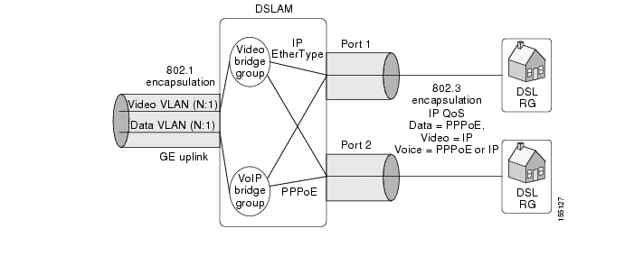
In the EtherType access architecture, the EtherType field of Ethernet packets is used to distinguish between two different address spaces. In this architecture the Internet access service is assumed to use PPPoE encapsulation, while the video service is assumed to use IP encapsulation. When PPP and IP packets are carried over Ethernet, the EtherType field can be used to distinguish between these two types of packets. In the EtherType model the voice service must be carried in one of the two topologies represented by these two values of the EtherType field. Because a single VC is used for all services, the EtherType model assumes that Ethernet- or IP-layer QoS is used to provide the proper quality of service for each of the services. Figure 2-7 illustrates the EtherType access architecture, where the DSLAM maps the Ethertype value on the DSL line to service VLANs in the GE uplink.
Figure 2-7 EtherType Access Architecture
Multi-VLAN Access Architecture
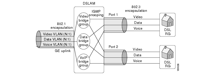
In the multi-VLAN access architecture, 802.1q encapsulation is used on the DSL line, and separate VLAN IDs are used to distinguish the address spaces for the different services. The DSLAM may then map these VLAN IDs on the GE uplink to a separate set of VLAN IDs that identify the address space on that link. Because a single VC is used for all services, the VLAN model assumes that Ethernet or IP-layer QoS is used to provide the proper quality of service for each of the services. Figure 2-8 illustrates the VLAN access architecture, where the DSLAM maps the VLAN ID on the DSL line to service VLANs in the GE uplink.
Figure 2-8 Multi-VLAN Access Architecture
Service Mapping in the Aggregation Network
WT-101 also specifies two alternative VLAN architectures for mapping residential services to VLANs in the Ethernet aggregation network. The alternatives are called the N:1 VLAN architecture and the 1:1 VLAN architecture. The N:1 and 1:1 VLAN architectures are in fact defined in WT-101 as methods of mapping subscriber lines and services to VLANs. The N:1 model maps many subscriber lines and services to a single VLAN, while the 1:1 model maps each subscriber line to a separate VLAN.
N:1 VLAN Model
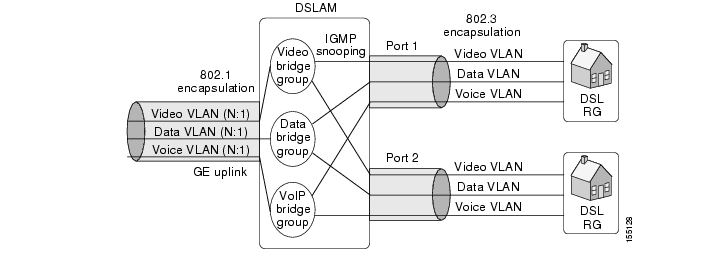
In the N:1 VLAN model, multiple subscribers and services are mapped to the same VLAN in the Ethernet aggregation network. There are many possibilities for mapping groups of subscribers and services to VLANs in this model. For example, each VLAN in the N:1 model may be used to aggregate all the subscribers associated with a particular service. When service mapping is implemented by means of the N:1 model, all the subscribers associated with a particular service and DSLAM are mapped to a single VLAN. The DSLAM performs an Ethernet bridging function between the DSL lines aggregated into a VLAN and the upstream Ethernet VLAN. One of the security issues associated with Ethernet bridging in WT-101 is that one subscriber may be able to snoop another subscriber's Ethernet frames. To alleviate this concern, WT-101 specifies that the DSLAM must support the ability to perform split-horizon forwarding between the DSL lines and the Ethernet uplink.
One of the architectural requirements of WT-101 is that subscriber transport sessions (PPPoE or DHCP sessions) be associated with the DSL line from which the session originated. Because a single VLAN in the N:1 VLAN model can represent many subscriber lines, the VLAN ID itself cannot be used to associate a DSL with a subscriber. WT-101 uses extensions to the transport session protocols themselves to provide subscriber line identification in the N:1 VLAN model. WT-101 specifies the use of PPPoE tags to provide the subscriber line ID function with PPoE sessions, and specifies the use of DHCP option 82 to provide the subscriber line ID function for DHCP sessions.
1:1 VLAN Model
In the 1:1 VLAN model, each subscriber line is identified in the aggregation network by means of a separate VLAN ID. This architecture is very similar to the original ATM-based DSL aggregation architecture, because each subscriber in the ATM architecture is identified at the BRAS by a separate ATM virtual circuit. Because of the number of bits in an 802.1q VLAN tag, Layer 2 aggregation networks that support more than 4096 subscribers must use 802.1ad encapsulation (Q in Q) to support the 1:1 VLAN model. In this model, the DSLAMs must map each DSL line to a separate VLAN tag on the Ethernet uplink. When 802.1q encapsulation is used, the DSLAM must map each DSL line to a separate 802.1q VLAN ID. When 802.1ad encapsulation is used, the DSLAM must map each DSL line to a separate set of inner and outer 802.1ad tags. The DSLAM forwarding model used for 1:1 VLAN aggregation is a simple cross connect model. The DSLAM simply forwards all packets from (or to) a specific DSL line and access service identification tag (VC, VLAN, or EtherType value) to (or from) a specific VLAN ID on the upstream GE port.
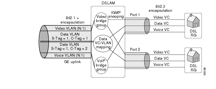
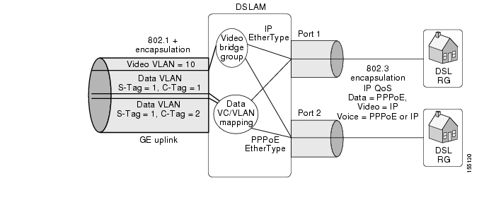
While WT-101 does not specify the mapping between a DSL line and a set of 802.1ad tags, a straightforward mapping that simplifies the requirements of the Layer 2 aggregation network involves mapping a DSL line ID to the inner VLAN ID (C-tag) and a unique DSLAM ID to the outer VLAN ID (S-tag). When this form of mapping is used, a Layer 2 aggregation network that supports only 802.1q encapsulation can be used for aggregation, because service mapping for N:1 services is performed by means of an 802.1q tag and for 1:1 services by means of 802.1ad S-tag. Figure 2-9 illustrates a multi-VC access architecture, where the DSLAM maps voice and video VCs to service (N:1) VLANs, while Internet access VCs are mapped to per-subscriber (1:1) VLANs. Figure 2-10 illustrates a single-VC access architecture, where the DSLAM maps voice and video VCs to service (N:1) VLANs, while Internet access VCs are mapped to per-subscriber (1:1) VLANs.
When service mapping is used in the Layer 2 aggregation network, the 1:1 VLAN model can be used for some services, while the N:1 VLAN model can be used for other services. The solution transport architecture makes use of this functionality to enable the Internet access service to use 1:1 VLANs, while the video service uses N:1 VLANs. When the 1:1 VLAN service is implemented by means of 802.1ad encapsulation, the 1:1 subscriber-line-to-VLAN mapping scheme described in the previous paragraph can be configured to ensure that the S-tag generated by the DSLAM for the Internet access service is different from the 802.1q tag generated for the video service. This configuration enables the Layer 2 aggregation network to separate the logical topologies for Internet access and video by using only the 802.1q VLAN/802.1ad S-tag.
Figure 2-9 1:1 + N:1 Service Mapping in a Multi-VC Access Architecture
Figure 2-10 1:1 + N:1 Service Mapping in an EtherType Access Architecture
WT-101 QoS Architecture
The requirements specified in WT-101 enable either a centralized or distributed QoS architecture to be implemented in the access and aggregation networks.
Centralized QoS Architecture
In the centralized QoS architecture, all QoS functionality is implemented in the BRAS if the Layer 2 aggregation nodes and DSLAMs are not QoS capable. In this architecture, the BRAS essentially models both the aggregation and access networks by using the three-level hierarchical shaping and scheduling algorithms described in DSL Forum TR-59. The centralized QoS model also assumes that all traffic for all downstream services goes through a single BRAS node.
Note
www.dslforum.org/techwork/tr/TR-059.pdfA centralized QoS architecture in which all QoS is implemented in the BRAS implies that all multicast replication is also done centrally in the BRAS. WT-101 Multicast Architecture, provides details of both the centralized and distributed multicast replication architectures associated with the WT-101 specification.
Distributed QoS Architecture
In a distributed QoS architecture, all QoS is implemented by means of schedulers on physical links. In a this architecture, any physical link that can experience congestion requires a packet scheduler that is capable of classifying and scheduling multiple classes of traffic. The IETF DiffServ architecture (RFC 2475) is an example of a distributed QoS architecture.
The transport architecture relies on a distributed QoS architecture. (For details, see QoS Architecture.)
WT-101 Layer 3 Edge Architecture
The requirements specified in WT-101 enable either a single or multiple Layer 3 edge architecture to be implemented.
Single Layer 3 Edge
In a single Layer 3 edge architecture, all services are terminated in a single BRAS node. The single edge architecture is required in networks that use a centralized QoS model.
Multiple Layer 3 Edge
In the multiple Layer 3 edge architecture, different services may be terminated in different Layer 3 edge nodes. This could be done by mapping different services to different VLAN IDs at the DSLAM, or it could be done through ARP resolution to different Layer 3 edge nodes serving different service-specific subnets.
The solution transport architecture uses a multiple Layer 3 edge architecture, where different services are mapped to different VLANs at the DSLAM.
WT-101 Multicast Architecture
The requirements specified in WT-101 support either a centralized or a distributed replication model for multicast replication.
Centralized Replication
In the centralized replication architecture, all multicast replication is performed at the BRAS. This has a fairly significant impact on the bandwidth used for a video broadcast service, because all broadcast video streams are essentially unicast from the BRAS. (For an analysis of the bandwidth usage associated with centralized vs. distributed multicast replication architectures, see Distributed vs. Centralized Replication Bandwidth.)
While not explicitly specified in WT-101, there is an implicit assumption that all multicast replication be performed in the BRAS when the centralized QoS architecture is used. The reason this assumption is implied is because when multicast traffic is replicated at a node downstream of the BRAS, that node essentially injects traffic that has not been modeled in the hierarchical scheduler of the BRAS. The traffic that is injected could then cause congestion at the node performing replication, resulting in video packets being dropped because of that congestion.
Section 6.3.2.2 of WT-101 ("IGMP Correlation at the BNG for HS and User Statistics") describes a method by which the BRAS could potentially change the shaping rate of a shaper dynamically, to avoid congestion from a downstream node that performs multicast replication based on the receipt of IGMP messages. Unfortunately, this scheme has timing issues associated with the IGMP state machine. These timing issues could potentially cause packet drops for the video service during channel-change events. The timing issue with the IGMP state machine is that IGMP is inherently a nonacknowledged asynchronous protocol. A node such as a DSLAM or aggregation switch that uses IGMP snooping to perform multicast replication can start the replication associated with incoming IGMP messages before the BRAS ever modifies the downstream shaping rate based on the receipt of that IGMP message. This timing window could be on the order of hundreds of milliseconds, and could result in video packets being lost because of congestion during this period.
Distributed Replication
In the distributed replication architecture, the Layer 3 edge, aggregation, and access nodes all perform replication. Layer 3 capable nodes perform replication using IP multicast, while Layer 2 capable nodes perform replication using IGMP snooping. When distributed replication is used, there is an implicit assumption that the N:1 VLAN architecture is used for multicast video. A single VLAN is required for multicast video to enable a single copy of the multicast video stream to be replicated to multiple subscribers.
The use of distributed replication also implies that a distributed QoS architecture is used. Distributed replication implies distributed QoS, because there are multiple points in the network that can inject video traffic that needs to be isolated at the QoS layer from other traffic (such as Internet access traffic). With distributed replication, any node that performs multicast replication must also be capable of scheduling multiple QoS classes on the physical link the replication is performed on.
Distributed vs. Centralized Replication Bandwidth
Because broadcast video streams are unicast from the BRAS in the centralized replication model, the amount of bandwidth needed for the broadcast video service in the distribution network scales with the number of subscribers—as opposed to the number of broadcast channels offered. Because there are typically many more subscribers served by single BRAS than the number of broadcast channels offered by a broadcast service, the result is that much more bandwidth is used for the broadcast service than with a distributed replication architecture. The bandwidth savings associated with distributed replication results in more bandwidth being available in the distribution and aggregation networks for nonguaranteed bandwidth services such as Internet access.
Statistical Analysis
The section describes a statistical analysis model that was used to compare the bandwidth used for distributed vs. centralized multicast replication. The analysis uses probability to determine the amount of bandwidth that would be needed to serve a population of subscribers using a broadcast TV service.
In this analysis, each subscriber is modeled as a random process selecting a channel to watch according to a given probability distribution across all possible channels. Given a group of channels, the average bandwidth required by the channels in use is calculated, given the "popularity" probabilities of the channels.
Because we are interested in determining the average number of channels in use, we can consider the channels to be probabilistically independent of each other and consider the channels one at a time.
For a single channel, the probability that this channel is idle is calculated as follows:
Let
p = P{a subscriber will tune to this channel}
N = Number of subscribers subtended by the given AR or DSLAM
so that
P{channel is idle} = (1 - p)N
For multiple channels, we sum the above expression.
Let
C = Number of channels
pk = P{a subscriber will tune to kth channel}
so that the average number of channels in use, CIU, is
Here, bandwidth = CIU.
When centralized replication is used, one channel is being transmitted to every active subscriber, so the same channel can be transmitted multiple times if it is being viewed by multiple subscribers.
Let
r = Total channel take rate or the P{subscriber is active} or sum over all channels of pk, the channel popularity
N = Number of subscribers
Here, bandwidth = Nr.
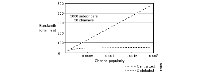
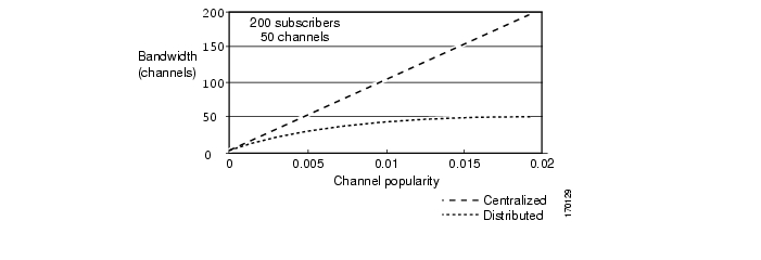
The graphs below chart the results of the statistical analysis described above, which compares bandwidth used in centralized vs. distributed multicast replication. Figure 2-11 shows the bandwidth savings for distributed vs. centralized multicast replication with a population of 5000 subscribers, while Figure 2-12 shows the bandwidth savings for distributed vs. centralized multicast replication with a population of 200 subscribers.
Figure 2-11 Bandwidth for Centralized vs. Distributed Replication with 5000 Subscribers
Figure 2-12 Bandwidth for Centralized vs. Distributed Replication with 200 Subscribers
In the centralized replication model, each channel is sent as a unicast stream from the replication source. Because of this, the bandwidth scales linearly with the number of subscribers, as opposed to the number of channels. In the distributed replication model, only one copy of each channel is sent, independent of the number of subscribers watching it. Consequently, the amount of bandwidth that is sent in the distributed replication model is capped at the bandwidth determined by the number of channels that are broadcast.
As illustrated in Figure 2-11 and Figure 2-12, the amount of bandwidth saved in the distributed replication model increases with the number of subscribers served. This is because the bandwidth scales in the distributed replication model with the number of channels, while the bandwidth scales in the centralized replication model with the number of subscribers.
Bandwidth Provisioning Model
In addition to providing additional bandwidth for services such as Internet access, distributed replication can also save on the amount of bandwidth that needs to be provisioned for the combination of broadcast video and VoD services in the distribution and aggregation networks. When broadcast video and VoD services are deployed to set-top boxes (STBs), each STB is typically capable of consuming a single broadcast or on-demand video stream.
The following presents a variety of useful equations.
Bandwidth Requirement for Aggregation and Distribution Networks for VoD
Because VoD services are delivered as unicast streams from a video headend, the amount of bandwidth that needs to be provisioned in the aggregation and distribution networks for a VoD service can be determined by the following equation:
Bandwidth = Video_Subs * Stream_Bandwidth * (Peak_Take_Rate / 100)
where
Video_Subs = Number of subscribers served by a node
Stream_Bandwidth = Amount of bandwidth per video stream
Peak_Take_Rate = Maximum expected use of the service as a percentage of video subscribers
Bandwidth Requirement for Broadcast Video with Unicast Centralized Replication
If the broadcast video service is delivered from the BRAS as unicast streams through the use of centralized replication, then the amount of bandwidth that needs to be provisioned for the broadcast service can be determined by using the same formula above.
Bandwidth Requirement for Broadcast Video with Distributed Multicast Replication
If the broadcast video service is delivered by means of distributed multicast replication, then the amount of bandwidth required for the broadcast service can be determined by the following equation:
Bandwidth = Min (Video_Subs, Num_Channels) * Stream_Bandwidth
where
Num_Channels = Number of channels delivered by the broadcast service
Bandwidth Requirement for Broadcast and On-Demand Video with Distributed Replication
When a VoD service is combined with a broadcast service that is delivered by means of distributed replication, the bandwidth for the broadcast and VoD services can be added to determine the total bandwidth required for both services. The following equation can be used to determine the amount of bandwidth required when a VoD service is combined with a broadcast service that uses distributed replication.
Bandwidth = Video_Subs * Stream_Bandwidth * (VoD_Peak_Take_Rate / 100) +
Min (Video_Subs, Num_Channels) * Stream_Bandwidthwhere
VoD_Peak_Take_Rate = Maximum expected usage of the VoD service as a percentage
of video subscribersBandwidth Requirement for Broadcast and On-Demand Video with Centralized Replication
When a VoD service is combined with a broadcast service delivered by means of centralized replication, the fact that an STB can consume a single VoD or broadcast stream results in the following equation to determine the required bandwidth for both services:
Bandwidth = Video_Subs * Stream_Bandwidth * Max (VoD_Peak_Take_Rate, Broadcast_Peak_Take_Rate)
where
Broadcast_Peak_Take_Rate = Maximum expected use of the broadcast service as a percentage of video subscribers
Because the peak take rate for the broadcast service is typically much higher than that for the VoD service, the amount of bandwidth that is needed for broadcast and VoD services can be much higher when the broadcast service is delivered as unicast streams rather than by means of distributed replication.
The example below uses the following numbers to determine the amount of bandwidth needed to implement a hypothetical video service that uses both distributed and centralized replication architectures for the broadcast video service.
Video_Subs = Number of video subscribers serviced by BRAS = 30,000
Num_Channels = 200
Stream_Bandwidth = 3.75 Mbps
VoD_Peak_Take_Rate = 10%
Broadcast_Peak_Take_Rate = 40%
In this example, the amount of bandwidth needed for the combined VoD and broadcast service from the BRAS when distributed replication is used is 12.75 Gbps, while the amount of bandwidth needed when centralized replication is used is 45 Gbps.
Solution Transport Recommendations Based on WT-101
The solution transport architecture uses distributed multicast replication (as described in WT-101 Multicast Architecture) to ensure maximum bandwidth efficiency for the broadcast video service. The use of distributed multicast replication means that a per-service (N:1) VLAN must be used for broadcast video traffic.
The solution transport architecture also uses a per-service VLAN for the VoD service. The use of per-service VLANs for both the broadcast video (multicast) and VoD (unicast) services enables the use of an aggregate—as opposed to a per-subscriber—QoS and forwarding model for video services. Potential Video Service Architectures, provides the background for why aggregate forwarding and QoS models are preferred for managed application services such as broadcast video, VoD, and voice.
While the solution transport architecture uses per-service VLANs for managed application services such as voice and video, it supports both per-service and per-subscriber (1:1) VLAN architectures for transport services such as Internet access. Service Mapping in the Aggregation Network, describes how a per-service VLAN architecture for managed application services such as video can be combined with a per-subscriber VLAN architecture for transport services such as Internet access.
As noted in Service Mapping in the Aggregation Network, WT-101 specifies that the access node or DSLAM is responsible for performing all VLAN tagging for both per-service and per-subscriber VLAN architectures. For per-subscriber (1:1) VLAN architectures, this means that the DSLAM must be capable of creating 802.1ad-encapsulated packets. Unfortunately, most DSLAMs do not currently support this capability. For this reason, this document recommends the use of per-service (N:1) VLANs for the Internet access service. Internet Access Forwarding, describes network designs for the Internet access service that include both per-service and per-subscriber VLAN architectures. The per-subscriber VLAN architecture described in that section makes use of DSLAM features that are not available on all DSLAM platforms.
The solution transport architecture uses a multiple Layer 3 edge architecture whereby different services are mapped to different VLANs at the DSLAM.
Service Mapping in the Access Network, describes the models included in WT-101 regarding how to distinguish among multiple service topologies on the DSL line. The solution transport architecture supports both the single-VC and multi-VC models of distinguishing different services on the DSL line. Edge Transport Architecture, describes the solution edge-transport architecture, which includes both the single-VC and multi-VC models in the DSL access network.
Service Mapping in the Aggregation Network, describes the transport session technologies used for services in WT-101. Because the solution transport architecture terminates the video service at a different Layer 3 edge node than does the Internet access service, different transport sessions are used for these services. Also, because the Internet access service is terminated in a BRAS, the solution transport architecture supports the use of both PPPoE and IP/DHCP as the encapsulation/transport session technologies for the Internet access service. The solution transport architecture supports IP/DHCP as the encapsulation/transport session technology for video services. IP/DHCP was chosen for video services because it makes multicast replication much more straightforward in Layer 2 capable nodes such as the DSLAM. These nodes perform replication by means of IGMP snooping. If PPPoE were used for video services, then these nodes would need to perform replication by snooping for IGMP messages inside of a PPPoE session. This is quite a bit more complex than performing native IGMP snooping, because the DSLAM would need to become PPPoE-session-aware as well as IGMP-aware.
The fact that the solution transport architecture uses distributed replication means that it also uses distributed QoS. Distributed replication implies distributed QoS because there are multiple points in the network that can inject video traffic, which must be isolated at the QoS layer from other traffic such as Internet access traffic. With distributed replication, any node that performs multicast replication must also be capable of scheduling multiple QoS classes on the physical link on which the replication is performed. As described in Potential Video Service Architectures, the QoS functionality on the BRAS is used simply to enforce the transport SLA for the Internet access service.
1 The AR is sometimes referred to as the provider-edge aggregation router, or PE-Agg.
![]()
![]()
![]()
![]()
![]()
![]()
![]()
![]()
Posted: Wed Sep 20 10:30:26 PDT 2006
All contents are Copyright © 1992--2006 Cisco Systems, Inc. All rights reserved.
Important Notices and Privacy Statement.