|
|

Table Of Contents
Implementing and Configuring the Solution
Configuring SSM Mapping with DNS Lookup
(Optional) Enabling Option 82 on the ARs
Configuring the 10-GE Ring Topology
Common Task: Configuring MPLS for HSD Service
Configuring the Hub-and-Spoke Topology
Common Task: Configuring QinQ and Spanning Tree
Implementing and Configuring the Solution
This chapter begins with tasks common to the 10-GE ring and hub-and-spoke topologies used in the Cisco Cisco Wireline Video/IPTV Solution:
It then presents the details of configuring each topology:
•
Configuring the 10-GE Ring Topology
•
Note
— Cisco 7600 Series Routers:
http://www.cisco.com/en/US/products/hw/routers/ps368/tsd_products_support_series_home.html
— Cisco Catalyst 6500 Series Switches:
http://www.cisco.com/en/US/products/hw/switches/ps708/tsd_products_support_series_home.html
Common Tasks
The following common tasks have general applicability and should be considered early in the implementation process:
•
•
Configuring SSM Mapping with DNS Lookup
As discussed in Multicast, Source Specific Multicast (SSM) is used simplify the configuration of a multicast network, and is common to both topologies. The solution uses edge devices that do not support IGMPv3. The switches accept IGMPv2 messages and convert these to IGMPv3 by resolving the source IP address of the multicast group by means of either a static mapping or a DNS resource record. This solution uses a DNS lookup method.
Note
http://www.cisco.com/univercd/cc/td/doc/product/software/ios123/123newft/123t/123t_2/gtssmma.htmThe following tasks are presented:
•
•
Configuring DNS Servers
The following steps are general. Refer to your DNS server documentation for details.
Step 1
Step 2
a.
b.
c.
d.
Configuring SSM Mapping on All Switches
Configure the following on all switches (the DER and the ARs) in both topologies.
Step 1
ip multicast routingStep 2
ip igmp ssm-map enable
Note
Step 3
Note
Configuring the Edge Switches for DNS Queries
On the edge switches that perform the DNS queries, you must configure the domain and IP addresses of the domain name servers. The domain for the multicast video in the following example is coronado.net. (Domain names will vary.) The switches send queries to the first DNS listed in the running configuration. If the first query fails, the next query is sent to the second DNS.
Step 1
ip domain multicast coronado.netStep 2
ip name-server 10.1.10.10Step 3
ip name-server 10.1.11.10(Optional) Enabling Option 82 on the ARs
The DHCP relay agent information option (option 82) enables a Dynamic Host Configuration Protocol (DHCP) relay agent to include information about itself when forwarding client-originated DHCP packets to a DHCP server. The DHCP server can use this information to implement IP address or other parameter-assignment policies.
Note
http://www.cisco.com/en/US/products/sw/iosswrel/ps1839/products_white_paper09186a0080087ad8.shtmlThe default behavior on the switches used in the solution is to reset the option 82 field in DHCP packets. If the gateway address is set to all zeros in the DHCP packet and the relay information option is already present in the packet, the DHCP relay agent discards the packet. Consequently, where DSLAMs are configured to insert option 82 in the DHCP packets from the set-top box (STB), this default behavior must be overridden. This is done on each aggregation router (AR) connected to a DSLAM that is configured to support option 82, with the following global command:
ip dhcp relay information trust-all
This configures all interfaces on the router as trusted sources of the DHCP relay information option.
Configuring the 10-GE Ring Topology
This section presents the following major topics:
•
Introduction
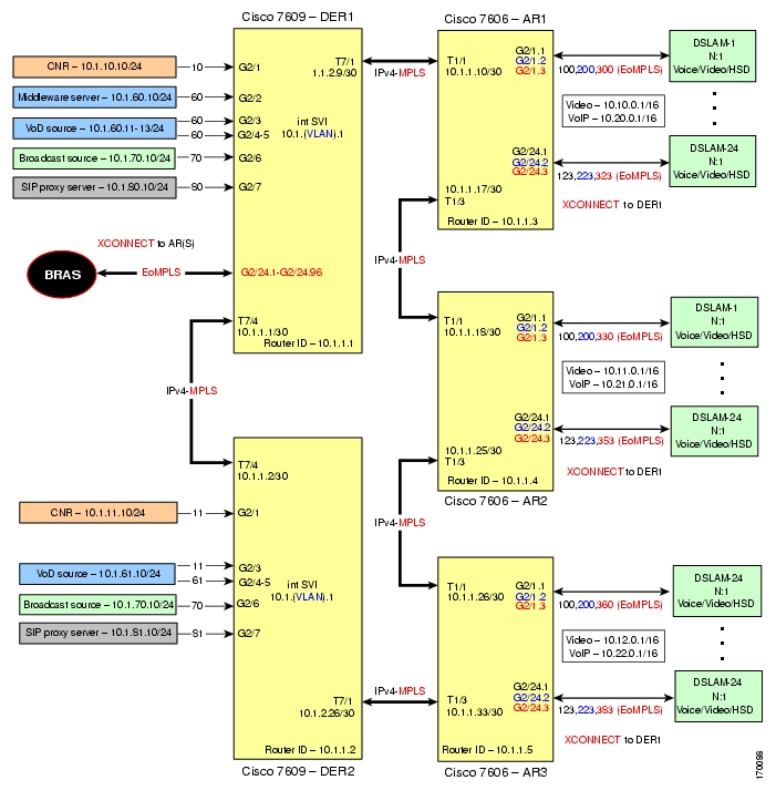
Figure 4-1 illustrates the 10-GE ring topology used in the solution. (See Configuration 1: 10-GE Layer 3 Ring.) All video sources and VoIP servers are connected to ports on the distribution edge routers (DERs). With two DERs in the topology, we can provide source, node, and network redundancy for each of the aggregation routers (ARs). Policy maps are applied to the DER ingress ports in order to mark the DSCP values of the different service types. In this example, only DER1 is connected to a middleware server.
Traffic is routed among DERs and ARs through 10-GE bidirectional transport links. Transport links are Layer 3 ports, and carry both IPv4 and Multiprotocol Label Switching (MPLS) packets. Video and VoIP traffic is routed over the transport links as native IPv4 packets. HSD is routed over the same transport links, but is encapsulated in MPLS through Ethernet over MPLS (EoMPLS) point-to-point connections. A single OSPF process is needed for the routing protocol.
The topology assumes that each DSLAM is configured to use the N:1 model for the three services—video, VoIP, and high-speed data (HSD). Therefore, each DSLAM is assigned three unique VLANs, one VLAN per service. (Note that VLANs have local significance, and are not bridged between DSLAMs attached to a common AR.)
The residential gateways (RGs) used in the test bed provided service mapping based on physical ports, as described in Physical Port-Based Traffic Mapping for the Multi-VC and VLAN Access Models.
Figure 4-1 10-GE Ring Topology
The switches in Figure 4-1 use the line cards, hardware versions, and IOS versions listed in Table 4-1.
Table 4-1 Hardware and IOS Versions for the 10-GE Ring Topology
DER1,
DER21
WS-X6724-SFP1
2.3
12.2(18)SXF2
WS-F6700-DFC3BXL
5.2
2
5
WS-SUP720-BASE
3.1
WS-F6K-PFC3BXL
1.2
WS-SUP720 (MFSC)
2.1
7
WS-X6704-10-GE
2.2
WS-F6700-DFC3BXL
4.0
AR1
1
WS-X6704-10GE
2.2
WS-F6700-DFC3BXL
4.0
2
WS-X6724-SFP
2.3
WS-F6K-DFC3BXL
5.2
5
WS-SUP720-3BXL
4.3
WS-F6K-PFC3BXL
1.6
WS-SUP720 (MFSC)
2.3
AR2
1
WS-X6704-10GE
2.2
WS-F6700-DFC3BXL
4.0
2
WS-X6724-SFP
2.3
WS-F6700-DFC3BXL
5.2
5
WS-SUP720-3BXL
4.3
WS-F6K-PFC3BXL
1.6
WS-SUP720 (MFSC)
2.3
AR3
1
WS-X6704-10GE
2.2
WS-F6700-DFC3BXL
4.0
2
WS-X6724-SFP
2.3
WS-F6700-DFC3BXL
5.2
5
WS-SUP720-3BXL
4.3
WS-F6K-PFC3BXL
1.6
WS-SUP720 (MFSC)
2.3
1 WS-X6748-GE-TX line cards, version 2.2, were also tested. To simplify the configuration details, they are not shown here.
Table 4-2 lists VLANs, their descriptions (service types), and IP addresses, for the DER and ARs in Figure 4-1. A range of VLANs is required for each AR, with one VLAN per DSLAM required to support EoMPLS for HSD.
Note
Table 4-3 lists the parameters used to configure the residential gateway (RG) tested in this topology.
Note
Table 4-3 RG Configuration Parameters
HSD
90
0
1
8
35
LLC
UBR
—
—
—
VoIP
1x07
1
4
0
51
CBR
—
300
—
Video
1x1
2, 3
7
8
59
VBR-RT
1200
600
10
1 Permanent virtual connection
2 Virtual path identifier
3 Virtual connection identifier
4 Peak cell rate
5 Sustained cell rate
6 Maximum burst size
7 The x corresponds to the AR number 1, 2, or 3 in the corresponding VLAN
Common Task: Configuring MPLS for HSD Service
Because EoMPLS is used on the trunk to the BRAS (as well as between the ARs and the DSLAMs), MPLS is required to support high-speed data (HSD) on the transport links between the DER and AR nodes.
Note
http://www.cisco.com/univercd/cc/td/doc/product/software/ios121/121newft/121limit/121ex/121ex8a/eompls9.htmTable 4-4 lists the loopback addresses used for MPLS. Loopback3 is used throughout for this purpose.
Table 4-4 Loopback Addresses for MPLS
DER1
10.1.254.1/32
DER2
10.1.254.2/32
AR1
10.1.254.3/32
AR2
10.1.254.4/32
AR3
10.1.254.5/32
Do the following in global configuration mode to enable MPLS on all nodes. (Loopback interfaces are later established on each node for MPLS in interface configuration mode.)
Step 1
mpls label protocol ldpStep 2
tag-switching advertise-tags for LOOPBACKtag-switching tdp router-id Loopback3 forceStep 3
no tag-switching advertise-tagsip access-list standard LOOPBACKpermit 10.1.254.0 0.0.0.255Step 4
Configuring DER1
This section addresses the configuration required on the switch labeled DER1 in Figure 4-1, to route multiple services from that switch to the ARs.
Note
This section addresses the following:
•
•
Note
Configuring QoS on DER1
This section presents the following topics:
•
•
Overview of QoS on a Cisco 7600 Series and Cisco Catalyst 6500 Series
This section addresses the configuration of quality of service (QoS) on the DER, through marking, classification, mapping, and queueing, to provide different degrees of quality of service for the different types of services supported by the solution architecture. For example, it is important to ensure the expeditious delivery of video and VoIP traffic, while providing only best-effort delivery for high-speed data (HSD).
By default, the Cisco 7600 series router and Cisco Catalyst 6500 series switch do not trust the incoming QoS markings, and therefore rewrite these bits with zeros. In this solution, packets at the network ingress ports are identified, classified, and marked according to type of traffic. The packets are marked with one of 64 possible Differentiated Services Code Point (DSCP) values at the ingress ports. These in turn are internally mapped to one of eight possible Class of Service (CoS) values, because CoS is used to determine the appropriate transmit queue for each packet. Queueing is configured on the individual 10-GE interfaces.
Note
http://www.cisco.com/warp/public/cc/pd/iosw/iore/tech/osfea_wp.htmConfiguring Marking and Classification on DER1
Do the following to enable marking and classification on DER1.
Step 1
mls qosStep 2
mls ip multicast replication-mode ingress
Note
Step 3
ip access-list extended acl_VoD_and_SIP_signalingpermit tcp 10.1.60.0 0.0.0.255 anypermit tcp 10.1.61.0 0.0.0.255 anypermit tcp 10.1.80.0 0.0.0.255 anypermit tcp 10.1.81.0 0.0.0.255 anyip access-list extended acl_video_VoDpermit udp 10.1.60.0 0.0.0.255 any20 permit udp 10.1.61.0 0.0.0.255 anyip access-list extended acl_video_broadcastpermit udp 10.1.70.0 0.0.0.255 232.0.0.0 0.255.255.255Step 4
class-map match-all class_VoIPmatch access-group name acl_VoIPclass-map match-all class_VoD_and_SIP_signalingmatch access-group name acl_VoD_and_SIP_signalingclass-map match-all class_video_broadcastmatch access-group name acl_video_broadcastclass-map match-all class_video_VoDmatch access-group name acl_video_VoDStep 5
policy-map setDSCPdescription Mark DSCP values for ingress trafficclass class_VoD_and_SIP_signalingset dscp cs3class class_video_broadcastset dscp af41class class_video_VoDset dscp af42class class_VoIPset dscp efStep 6
service-policy input setDSCP
Note
Step 7
mls qos trust dscpConfiguring Mapping on DER1
For background, see the following:
•
•
http://www.cisco.com/univercd/cc/td/doc/product/lan/cat4000/12_18a/config/qos.htm#59874
Do the following to configure mapping on DER1.
Step 1
Note
Note
DER1# show mls qos maps dscp-cos
Dscp-cos map: (dscp= d1d2)d1 : d2 0 1 2 3 4 5 6 7 8 90 : 00 00 00 00 00 00 00 00 01 011 : 01 01 01 01 01 01 02 02 02 022 : 02 02 02 02 03 03 03 03 03 033 : 03 03 04 04 04 04 04 04 04 044 : 05 05 05 05 05 05 05 05 06 065 : 06 06 06 06 06 06 07 07 07 076 : 07 07 07 07This table shows the following default mapping (36 corresponds to DSCP AF41):
Step 2
The solution specifies the following DSCP-to-CoS mapping:
a.
mls qos map dscp-cos 36 to 2b.
DER1# show mls qos maps dscp-cosDSCP-CoS Mapping Table (dscp = d1d2)d1 : d2 0 1 2 3 4 5 6 7 8 90 : 00 00 00 00 00 00 00 00 01 011 : 01 01 01 01 01 01 02 02 02 022 : 02 02 02 02 03 03 03 03 03 033 : 03 03 04 04 04 04 02 04 04 044 : 05 05 05 05 05 05 05 05 06 065 : 06 06 06 06 06 06 07 07 07 076 : 07 07 07 07Establishing and Configuring Interfaces on DER1
Refer to Figure 4-1.
This section addresses the following:
•
•
•
•
Establishing VLANs for Services on DER1
Before the 1-GE interfaces can be configured, VLANs for the various services must be created. (See Table 4-2.)
Tip
Step 1
a.
vlan 10name VLAN_10_Managementb.
interface Vlan10description Management VLAN (Middleware, DNS, DHCP, etc)ip address 10.1.10.1 255.255.255.0no ip redirectsno ip unreachablesc.
load-interval 30d.
Unicast Video Aggregation
vlan 60name VLAN_60_Unicast_Videointerface Vlan60description VoD server VLAN (Unicast Video)ip address 10.1.60.1 255.255.255.0no ip redirectsno ip unreachablesload-interval 30VoIP
vlan 80name VLAN_80_VoIPinterface Vlan80description VoIP gateway VLANip address 10.1.80.1 1 255.255.255.0no ip redirectsno ip unreachablesload-interval 30Step 2
a.
vlan 70name VLAN_70_Multicast_Videob.
interface Vlan70description Broadcast video source VLAN (Multicast Video)ip address 10.1.70.1 255.255.255.0no ip redirectsno ip unreachablesc.
ip pim sparse-moded.
load-interval 30Establishing an EoMPLS Interface to the BRAS
Do the following to establish an Ethernet over Multiprotocol Label Switching (EoMPLS) interface to the broadband remote access server (BRAS).
Note
Step 1
interface GigabitEthernet2/24description To/From BRAS for 10GE Ring EoMPLSno ip addressStep 2
carrier-delay msec 0dampeningStep 3
load-interval 30Step 4
Note
wrr-queue bandwidth 64 255 0wrr-queue queue-limit 40 50 0wrr-queue threshold 2 80 100 100 100 100 100 100 100wrr-queue random-detect min-threshold 1 75 100 100 100 100 100 100 100wrr-queue random-detect max-threshold 1 100 100 100 100 100 100 100 100no wrr-queue random-detect 2wrr-queue cos-map 1 1 0 1wrr-queue cos-map 2 2 3 4 6 7Step 5
a.
interface GigabitEthernet2/24.1description HSD to/from DSLAM1 on AR1encapsulation dot1Q 300
Note
b.
xconnect 10.1.254.3 300 encapsulation mplsc.
interface GigabitEthernet2/24.2description HSD to/from DSLAM1 on AR2encapsulation dot1Q 330xconnect 10.1.254.4 330 encapsulation mpls!interface GigabitEthernet2/24.3description HSD to/from DSLAM1 on AR3encapsulation dot1Q 360xconnect 10.1.254.5 360 encapsulation mplsd.
Establishing 1-GE Interfaces for Servers and Management on DER1
VoD servers, high-speed data sources, and management resources connect to Layer 2 interfaces on DER, and their traffic is aggregated into the appropriate service VLANs.
The following is configured on DER1.
Step 1
a.
interface GigabitEthernet2/1description CNR ingress/egress (DHCP, DNS, TFTP, SysLog)no ip addressb.
switchportswitchport mode accessswitchport access vlan 10c.
carrier-delay msec 0dampeningd.
load-interval 30e.
no cdp enablef.
Note
spanning-tree portfastg.
spanning-tree bpduguard enable
Note
h.
service-policy input setDSCPStep 2
Kasenna Middeware Server
interface GigabitEthernet2/2description Kasenna Middleware Server ingress/egressswitchportswitchport access vlan 10Kasenna VoD Pump Management Port (Eth0)
interface GigabitEthernet2/3description VoD Pump ingress/egressswitchportswitchport access vlan 60Kasenna VoD Pump (HPN0)
interface GigabitEthernet2/3description VoD Pump (HPN0) ingress/egressswitchportswitchport access vlan 60Kasenna VoD Pump (HPN1)
interface GigabitEthernet2/3description VoD Pump (HPN1) ingress/egressswitchportswitchport access vlan 60Broadcast Server (Multicast)
interface GigabitEthernet2/6description Broadcast Video ingress/egressswitchportswitchport access vlan 70VoIP—SIP Proxy Server
interface GigabitEthernet2/7description SIP Proxy Server ingress/egressswitchportswitchport access vlan 80
Note
Establishing 10-GE Interfaces for Transport on DER1
The 10-GE trunk interfaces create the ring topology from DER1 through the ARs and back to the DER2. The following is configured on DER1.
Step 1
a.
interface TenGigabitEthernet7/4description Transport to/from Ring AR1 (TenGig1/1)ip address 10.1.1.1 255.255.255.252b.
Note
carrier-delay msec 0dampening 5 1000 2000 20 restart 16000c.
load-interval 30d.
ip pim query-interval 100 msec
Note
http://www.cisco.com/univercd/cc/td/doc/product/software/ios123/123tcr/123tip3r/ip3_i2gt.htm#wp1069550e.
ip pim sparse-modef.
ip ospf network point-to-pointip ospf hello-interval 1
Note
Step 2
Note
http://www.cisco.com/warp/public/cc/pd/si/casi/ca6000/prodlit/buffe_wp.htma.
queue thresh cos-map---------------------------------------1 1 01 2 12 1 22 2 3 43 1 6 78 1 5b.
wrr-queue cos-map 1 1 0 1wrr-queue cos-map 2 2 3 4 6 7
Note
c.
queue thresh cos-map---------------------------------------1 1 0 12 1 22 2 3 4 6 78 1 5d.
TxQueue1 uses Weighted Random Early Drop (WRED) for queue-congestion management. Only HSD is queued in this queue, and when the amount of HSD in the queue reaches 75%, random packets are dropped in an attempt to keep the queue from reaching 100% utilization.
wrr-queue random-detect min-threshold 1 75 100 100 100 100 100 100 100wrr-queue random-detect max-threshold 1 100 100 100 100 100 100 100 100TxQueue2 uses tail drop for queue congestion management. VoD is assigned to the threshold 1 and is dropped once the queue reaches 80% utilization. VoD signaling, network signaling, and broadcast video are assigned to the third threshold 2 and are dropped once the queue reaches 100% utilization.
wrr-queue threshold 2 80 100 100 100 100 100 100 100no wrr-queue random-detect 2e.
The weighted queues need to be modified to handle our modified TxQueue mappings. The ratio between TxQueue2 and TxQueue1 is 255/64 = 4, so TxQueue2 needs four times as much bandwidth as TxQueue1. Therefore, TxQueue1 is allocated 20% of the bandwidth on the interface, and TxQueue2 is allocated 80% of the bandwidth.
wrr-queue bandwidth 64 255 0 0 0 0 0f.
Each line card has a limited amount of buffer for the transmit queues. For this interface, 40% of the buffer is allocated for TxQueue1, and 50% of the buffer is allocated for TxQueue2.
wrr-queue queue-limit 40 50 0 0 0 0 0g.
mls qos trust dscpStep 3
h.
interface TenGigabitEthernet7/1description Transport to/from Ring AR1 (TenGig1/1)i.
Step 4
Note
a.
interface loopback 3description Loopback interface for MPLSip address 10.1.254.1 255.255.255.255b.
tag-switching ipc.
mtu 9216Configuring OSPF Routing for Video and Voice Traffic on DER1
Routing advertisements are enabled on the transport VLANs, but are turned off on the aggregation VLANs by means of the passive-interface command.
Step 1
router ospf 100router-id 10.1.1.1log-adjacency-changesa.
timers throttle spf 10 100 1000b.
timers throttle lsa all 1 10 1000c.
timers lsa arrival 100If an instance of the same LSA arrives sooner than the interval that is set, the LSA is dropped.
d.
ispfe.
passive-interface Vlan10passive-interface Vlan60passive-interface Vlan70passive-interface Vlan80f.
network 10.1.1.0 0.0.0.3 area 0network 10.1.1.8 0.0.0.3 area 0network 10.1.10.0 0.0.1.255 area 0network 10.1.60.0 0.0.0.255 area 0network 10.1.70.0 0.0.0.255 area 0network 10.1.70.0 0.0.0.255 area 0network 10.1.80.0 0.0.0.255 area 0g.
maximum-paths 8Configuring DER2
The configuration on DER2 is essentially the same as that on DER1, except that IP addresses and VLAN IDs differ, and no connection is made to a BRAS. The topics are summarized, with references, below.
•
•
Configuring QoS on DER2
Proceed as in Configuring QoS on DER1.
Establishing and Configuring Interfaces on DER2
Proceed as in Establishing and Configuring Interfaces on DER1.
For IP addresses and VLAN IDs, see Table 4-2.
For MPLS on transport interfaces, see Common Task: Configuring MPLS for HSD Service.
Configuring OSPF Routing for Video and Voice Traffic on DER2
Proceed as in Configuring OSPF Routing for Video and Voice Traffic on DER1
Configuring AR1
This section addresses the configuration required on the switch labeled AR1 in Figure 4-1, to route multiple services from AR1 to DER1 and AR2.
Note
This section addresses the following:
•
•
Note
Configuring QoS on AR1
See Overview of QoS on a Cisco 7600 Series and Cisco Catalyst 6500 Series. This section presents the following topics:
•
Configuring Marking and Classification on AR1
Do the following to enable marking and classification on AR1.
Step 1
mls qosStep 2
ip access-list extended acl_VoD_and_SIP_signalingpermit ip any host 10.1.10.10permit ip any host 10.1.60.0 0.0.0.255permit ip any host 10.1.61.10 0.0.0.255permit ip any host 10.1.80.10 0.0.0.255permit ip any host 10.1.81.10 0.0.0.255ip access-list extended acl_VoIPpermit udp any any range 16384 32767permit udp any range 16384 32767 anyStep 3
class-map match-all class_VoIPmatch access-group name acl_VoIPclass-map match-all class_VoD_and_SIP_signalingmatch access-group name acl_VoD_and_SIP_signalingStep 4
policy-map setDSCPdescription Mark DSCP values for ingress trafficclass class_VoIPset dscp efclass class_VoD_and_SIP_signalingset dscp cs3Step 5
service-policy input setDSCP
Note
Step 6
mls qos trust dscpConfiguring Mapping on AR1
To configure mapping on AR1, proceed as in Configuring Mapping on DER1.
Establishing and Configuring Interfaces on AR1
Refer to Figure 4-1.
This section addresses the following:
•
•
•
•
Establishing VLANs for Services on AR1
Proceed as in Establishing VLANs for Services and Transport on DER1, but make changes to IP addresses and VLAN IDs as indicated in Table 4-2.
Establishing 10-GE Interfaces for Transport on AR1
The 10-GE trunk interfaces provide the transport between AR1 and DER1 and AR2.
Note
Step 1
a.
interface TenGigabitEthernet1/1description Transport to/from DER1 (TenGig7/1)dampening 5 1000 2000 20 restart 16000ip address 10.1.1.10 255.255.255.252ip pim query-interval 100 msecip pim sparse-modeip ospf network point-to-pointip ospf hello-interval 1load-interval 30carrier-delay msec 0b.
wrr-queue bandwidth 64 255 0 0 0 0 0wrr-queue queue-limit 40 50 0 0 0 0 0wrr-queue threshold 2 80 100 100 100 100 100 100 100wrr-queue random-detect min-threshold 1 75 100 100 100 100 100 100 100wrr-queue random-detect max-threshold 1 100 100 100 100 100 100 100 100no wrr-queue random-detect 2wrr-queue cos-map 1 1 0 1wrr-queue cos-map 2 2 3 4 6 7mls qos trust dscpStep 2
interface TenGigabitEthernet1/3description Transport to/from AR2 (TenGig1/1)dampening 5 1000 2000 20 restart 16000ip address 10.1.1.17 255.255.255.252ip pim query-interval 100 msecip pim sparse-modeip ospf network point-to-pointip ospf hello-interval 1load-interval 30carrier-delay msec 0wrr-queue bandwidth 64 255 0 0 0 0 0wrr-queue queue-limit 40 50 0 0 0 0 0wrr-queue threshold 2 80 100 100 100 100 100 100 100wrr-queue random-detect min-threshold 1 75 100 100 100 100 100 100 100wrr-queue random-detect max-threshold 1 100 100 100 100 100 100 100 100no wrr-queue random-detect 2wrr-queue cos-map 1 1 0 1wrr-queue cos-map 2 2 3 4 6 7mls qos trust dscpConfigure Service Mapping for Video and VoIP Services on AR1
Service mapping on each DSLAM is achieved by using VLANs, with a single set of VLANs allocated to each DSLAM. There is a single VLAN per DSLAM, meaning that a VLAN defined on an AR will not span multiple DSLAMs on the AR. One VLAN is for video service, a second VLAN is for VoIP services, and a third VLAN is for high-speed data (HSD) services. (See Table 4-2.)
IP unnumbered is used to reduce the operational overhead associated with assigning unique IP subnets per VLAN. With IP unnumbered we can reduce operational overhead on the AR by assigning one /16 subnet to a service for all DSLAMs aggregated by the AR. With the exception of HSD, all interfaces are Layer 3 subinterfaces. HSD subinterfaces use EoMPLS at Layer 2 to bridge traffic across an MPLS transport link to a BRAS.
Note
Do the following to configure service mapping for video and VoIP services on AR1.
Step 1
a.
interface Loopback0description Address block for Video Services on AR1ip address 1.10.0.1 255.255.0.0ip ospf network point-to-pointload-interval 30interface Loopback1description Address block for VoIP services on AR1ip address 1.20.0.1 255.255.0.0ip ospf network point-to-pointload-interval 30b.
ip dhcp route connectedEstablishing 1-GE Subinterfaces to DSLAMs on AR1
Do the following to establish 1-GE subinterfaces to DSLAMs on AR1.
Step 1
a.
interface GigabitEthernet2/1description 802.1q Interface To DSLAM-1no ip addressb.
no cdp enablec.
load-interval 30d.
wrr-queue bandwidth 64 255 0wrr-queue queue-limit 40 50 0wrr-queue threshold 2 80 100 100 100 100 100 100 100wrr-queue random-detect min-threshold 1 75 100 100 100 100 100 100 100wrr-queue random-detect max-threshold 1 100 100 100 100 100 100 100 100no wrr-queue random-detect 2wrr-queue cos-map 1 1 0 1wrr-queue cos-map 2 2 3 4 6 7
Note
e.
interface GigabitEthernet2/1.1description Video edge VLANencapsulation dot1Q 100ip unnumbered Loopback0ip helper-address 10.1.10.10f.
service-policy input setDSCPg.
ip pim sparse-modeh.
ip ospf network point-to-pointip ospf hello-interval 1i.
ip igmp static-group 232.1.1.1 source ssm-mapip igmp static-group 232.1.1.2 source ssm-mapip igmp static-group 232.1.1.3 source ssm-mapip igmp static-group 232.1.1.4 source ssm-mapip igmp static-group 232.1.1.5 source ssm-mapip igmp static-group 232.1.1.6 source ssm-mapip igmp static-group 232.1.1.7 source ssm-mapip igmp static-group 232.1.1.8 source ssm-mapip igmp static-group 232.1.1.9 source ssm-mapip igmp static-group 232.1.1.10 source ssm-map
Note
http://www.cisco.com/univercd/cc/td/doc/product/software/ios123/123newft/123t/123t_2/gtssmma.htmj.
arp timeout 250
Note
k.
interface GigabitEthernet2/1.2description Voice edge VLANencapsulation dot1Q 200ip unnumbered Loopback1ip helper-address 10.1.10.10l.
service-policy input setDSCPm.
interface GigabitEthernet2/1.3description HSD edge VLANencapsulation dot1Q 300
Note
n.
xconnect 10.1.254.3 300 encapsulation mpls
Note
Step 2
Note
a.
interface loopback 3description Loopback interface for MPLSip address 10.1.254.2 255.255.255.255b.
tag-switching ipc.
mtu 9216Configuring OSPF Routing for Video and Voice Traffic on AR1
For background and details, refer to Configuring OSPF Routing for Video and Voice Traffic on DER1.
Do the following to configure OSPF routing for video and voice traffic on AR1.
Step 1
router ospf 100router-id 10.1.1.3ispflog-adjacency-changestimers throttle spf 10 100 1000timers throttle lsa all 1 10 1000timers lsa arrival 100network 10.1.1.8 0.0.0.3 area 0network 10.1.1.16 0.0.0.3 area 0network 10.1.254.3 0.0.0.0 area 0network 10.10.0.1 0.0.255.255 area 0network 10.20.0.1 0.0.255.255 area 0Configuring AR2
The configuration on AR2 is essentially the same as that on AR1, except that IP addresses differ. The topics are summarized, with references, below.
•
•
Configuring QoS on AR2
Proceed as in Configuring QoS on DER1.
Establishing and Configuring Interfaces on AR2
Proceed as in Establishing and Configuring Interfaces on DER1.
For IP addresses and VLAN IDs, see Table 4-2.
For MPLS on transport interfaces, see Common Task: Configuring MPLS for HSD Service.
Configuring OSPF Routing for Video and Voice Traffic on AR2
Proceed as in Configuring OSPF Routing for Video and Voice Traffic on DER1
Configuring AR3
The configuration on AR3 is essentially the same as that on AR1 and AR2, except that IP addresses differ. The topics are summarized, with references, below.
•
•
Configuring QoS on AR3
Proceed as in Configuring QoS on DER1.
Establishing and Configuring Interfaces on AR3
Proceed as in Establishing and Configuring Interfaces on DER1.
For IP addresses and VLAN IDs, see Table 4-2.
For MPLS on transport interfaces, see Common Task: Configuring MPLS for HSD Service.
Configuring OSPF Routing for Video and Voice Traffic on AR3
Proceed as in Configuring OSPF Routing for Video and Voice Traffic on DER1
Configuring the Hub-and-Spoke Topology
This section presents the following major topics:
•
Introduction
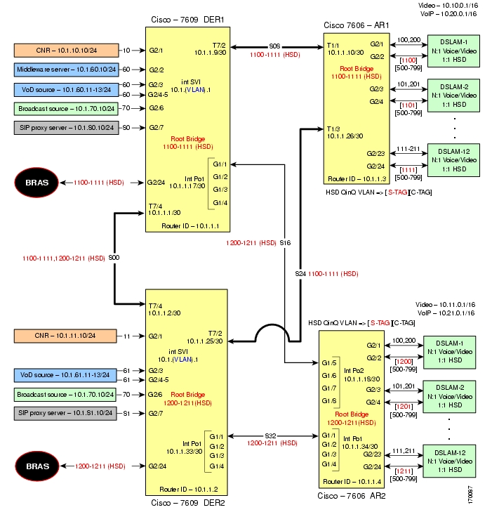
Figure 4-2 illustrates the hub-and-spoke topology used in the solution. (See Configuration 2: 1-GE plus 10-GE Hub and Spoke.) All video sources and VoIP servers are connected to ports on the distribution edge routers (DERs). With two DERs in the topology we are able to provide source, node, and network redundancy for each of the aggregation routers (ARs). Policy maps are applied to the DER ingress ports in order to mark the DSCP values of the different service types. In this example, only DER1 is connected to a middleware server.
Traffic is routed among DERs and ARs over 10-GE bidirectional and Nx1-GE transport links. Transport links are Layer 2 switchports that are defined as IEEE 802.1q trunks. Each transport link or trunk carries two VLANs; video and VoIP traffic is in one VLAN, and HSD or Internet traffic is in the second VLAN. IEEE 802.1q is needed, because HSD traffic is bridged on the transport links.
The hub-and-spoke topology assumes that each DSLAM uses the N:1 model for video and voice services, (one VLAN per service), and uses the 1:1 model for HSD services (one VLAN per subscriber). (Note that VLANs have local significance, and are not be bridged between DSLAMs attached to a common AR.)
The 1:1 model for HSD traffic does not scale, because of the number of service provider VLANs required to implement this model. Dot1q tunneling (QinQ) is used to reduce the number of VLANs required in the service provider network for HSD.
The residential gateways (RGs) used in the test bed provided service mapping based on physical ports, as described in Physical Port-Based Traffic Mapping for the Multi-VC and VLAN Access Models.
Figure 4-2 Hub-and-Spoke Topology
The switches in Figure 4-2 use the line cards, hardware versions, and IOS versions listed in Table 4-6.
Table 4-2 lists VLANs, their descriptions (service types), and IP addresses, for the DER and ARs in Figure 4-2.
Table 4-3 lists the parameters used to configure the residential gateway (RG). They are the same as those for the 10-GE symmetric topology.
Note
Common Task: Configuring QinQ and Spanning Tree
QinQ is used to connect HSD subscribers to a BRAS on one of the DER nodes, where dot1q tunnels terminate on the BRAS. This supports the requirement to have 1:1 VLANs on the DSLAM, where one VLAN is assigned to each subscriber for HSD. Assuming there are 300 subscribers per DSLAM, this would require 300 VLANs per DSLAM—making VLAN scalability an issue for the service provider. The AR port connecting the DSLAM to the service provider network adds an outer S-TAG to inner C-TAG, meaning one service provider VLAN is required per DSLAM.
HSD VLANs are bridged on the service provider network. In a hub-and-spoke network, each AR creates a Layer 2 loop that forces the provider to run spanning tree. Disable MAC address learning on the DER to conserve on MAC forwarding entries. MAC address learning is not needed when a logical topology consists of only two physical ports, because each MAC frame that arrives at one port is always sent on the other port. To create a two-port topology on the DER, configure each AR as the spanning tree root for its HSD VLANs. This causes Spanning Tree Protocol (STP) to block at the transport link between DER1 and DER2, creating point-to-point Layer 2 links between DER and AR. To improve STP time, the four switches are configured for IEEE 802.1w Rapid Spanning Tree Protocol (RSTP).
VLANs defined on AR1 are used for HSD traffic, with one service provider VLAN per DSLAMs. Each AR supports a maximum of 30 DSLAMs. Table 4-7 lists the VLAN ranges for the ARs.
Configuring DER1
This section addresses the configuration required on the switch labeled DER1 in Figure 4-2, to route multiple services from that switch to the ARs.
Note
This section addresses the following:
•
•
•
Note
Configuring QoS on DER1
This section presents the following topics:
•
•
Note
Overview of QoS on a Cisco 7600 Series and Cisco Catalyst 6500 Series
This section addresses the configuration of quality of service (QoS) on the DER, through marking, classification, mapping, and queueing, to provide different degrees of quality of service for the different types of services supported by the solution architecture. For example, it is important to ensure the expeditious delivery of video and VoIP traffic, while providing only best-effort delivery for high-speed data (HSD).
By default, the Cisco 7600 series router and Cisco Catalyst 6500 series switch do not trust the incoming QoS markings, and therefore rewrite these bits with zeros. In this solution, packets at the network ingress ports are identified, classified, and marked according to type of traffic. The packets are marked with one of 64 possible Differentiated Services Code Point (DSCP) values at the ingress ports. These in turn are internally mapped to one of eight possible Class of Service (CoS) values, because CoS is used to determine the appropriate transmit queue for each packet. Queueing is configured on the individual 10-GE interfaces.
Note
http://www.cisco.com/warp/public/cc/pd/iosw/iore/tech/osfea_wp.htmConfiguring Marking and Classification on DER1
Do the following to enable marking and classification on DER1.
Step 1
mls qosStep 2
mls ip multicast replication-mode ingress
Note
http://www.cisco.com/en/US/products/hw/routers/ps368/products_configuration_guide_chapter09186a0080435d12.htmlStep 3
ip access-list extended acl_VoD_and_SIP_signalingpermit tcp 10.1.60.0 0.0.0.255 anypermit tcp 10.1.61.0 0.0.0.255 anypermit tcp 10.1.80.0 0.0.0.255 anypermit tcp 10.1.81.0 0.0.0.255 anyip access-list extended acl_video_VoDpermit udp 10.1.60.0 0.0.0.255 anypermit udp 10.1.61.0 0.0.0.255 anyip access-list extended acl_video_broadcastpermit udp 10.1.70.0 0.0.0.255 232.0.0.0 0.255.255.255Step 4
class-map match-all class_VoIPmatch access-group name acl_VoIPclass-map match-all class_VoD_and_SIP_signalingmatch access-group name acl_VoD_and_SIP_signalingclass-map match-all class_video_broadcastmatch access-group name acl_video_broadcastclass-map match-all class_video_VoDmatch access-group name acl_video_VoDStep 5
policy-map setDSCPdescription Mark DSCP values for ingress trafficclass class_VoD_and_SIP_signalingset dscp cs3class class_video_broadcastset dscp af41class class_video_VoDset dscp af42class class_VoIPset dscp efStep 6
service-policy input setDSCP
Note
Step 7
mls qos trust dscpConfiguring Mapping on DER1
Do the following to configure mapping on DER1.
Step 1
Note
Note
DER# show mls qos maps dscp-cosDscp-cos map: (dscp= d1d2)d1 : d2 0 1 2 3 4 5 6 7 8 9-------------------------------------0 : 00 00 00 00 00 00 00 00 01 011 : 01 01 01 01 01 01 02 02 02 022 : 02 02 02 02 03 03 03 03 03 033 : 03 03 04 04 04 04 04 04 04 044 : 05 05 05 05 05 05 05 05 06 065 : 06 06 06 06 06 06 07 07 07 076 : 07 07 07 07This table shows the following mapping (36 corresponds to AF41):
Step 2
The solution specifies the following DSCP-to CoS-mappings:
a.
mls qos map dscp-cos 36 to 2b.
DER1# show mls qos maps dscp-cosDSCP-CoS Mapping Table (dscp = d1d2)d1 : d2 0 1 2 3 4 5 6 7 8 9-------------------------------------0 : 00 00 00 00 00 00 00 00 01 011 : 01 01 01 01 01 01 02 02 02 022 : 02 02 02 02 03 03 03 03 03 033 : 03 03 04 04 04 04 02 04 01 044 : 05 05 05 05 05 05 05 05 06 065 : 06 06 06 06 06 06 07 07 07 076 : 07 07 07 07Establishing and Configuring Interfaces on DER1
Refer to Figure 4-2.
This section addresses the following:
•
•
•
•
•
Establishing VLANs for Services and Transport on DER1
Before the 1-GE and 10-GE interfaces can be configured, VLANs for the various services must be created. With the exception of the VLAN range for high-speed data (HSD), these are all Layer 3 VLANs. (See Table 4-6.)
Do the following to establish VLANs for services and transport on DER1.
Tip
Step 1
a.
vlan 10name VLAN_10_Managementb.
interface Vlan10description Management VLAN (Middleware, DNS, DHCP, etc)ip address 10.1.10.1 255.255.255.0no ip redirectsno ip unreachablesc.
load-interval 30d.
vlan 60name VLAN_60_Unicast_Videointerface Vlan60description VoD server VLAN (Unicast Video)ip address 10.1.60.1 255.255.255.0no ip redirectsno ip unreachablesload-interval 30e.
vlan 80name VLAN_80_VoIPinterface Vlan80description VoIP gateway VLANip address 10.1.80.1 1 255.255.255.0no ip redirectsno ip unreachablesload-interval 30Step 2
a.
vlan 70name VLAN_70_Multicast_Videob.
interface Vlan70description Broadcast video source VLAN (Multicast Video)ip address 10.1.70.1 255.255.255.0no ip redirectsno ip unreachablesc.
ip pim query-interval 100 msec
Note
http://www.cisco.com/univercd/cc/td/doc/product/software/ios123/123tcr/123tip3r/ip3_i2gt.htm#wp1069550d.
ip pim sparse-modee.
load-interval 30Step 3
vlan 1100-1111,1200-1211Step 4
a.
vlan 800name Video/Voice_To/From_DER2b.
interface Vlan800description Transport VLAN to/from DER2ip address 10.1.1.1 255.255.255.252c.
ip pim query-interval 100 msecd.
ip pim sparse-modee.
ip ospf network point-to-pointip ospf hello-interval 1
Note
f.
load-interval 30Step 5
Voice/Video to/From AR1
vlan 808name Video/Voice_To/From_AR1interface Vlan808description Transport VLAN to/from AR1ip address 10.1.1.9 255.255.255.252ip pim query-interval 100 msecip pim sparse-modeip ospf network point-to-pointip ospf hello-interval 1load-interval 30Voice/Video to/From AR2
vlan 816name Video/Voice_To/From_AR2interface Vlan816description Transport VLAN to/from AR2ip address 10.1.1.17 255.255.255.252ip pim query-interval 100 msecip pim sparse-modeip ospf network point-to-pointip ospf hello-interval 1load-interval 30g.
no spanning-tree vlan 800,808,816Establishing a Tunnel to the BRAS
Do the following to establish a dot1q tunnel interface to the broadband remote-access server (BRAS). (See Common Task: Configuring QinQ and Spanning Tree.)
Note
Step 1
interface GigabitEthernet2/24description BRAS for HSD (Dot1q-Tunnel)switchportswitchport mode trunkno ip addressh.
switchport trunk encapsulation dot1qi.
switchport trunk allowed vlan 1100-111,1200-1211j.
load-interval 30k.
Step 2
Establishing 1-GE Interfaces for Servers and Management on DER1
VoD servers, high-speed data sources, and management resources connect to Layer 2 interfaces on DER1, and their traffic is aggregated into the appropriate service VLANs.
The following is configured on DER1.
Step 1
a.
interface GigabitEthernet2/1description CNR ingress/egress (DHCP, DNS, TFTP, SysLog)no ip addressb.
switchportswitchport mode accessswitchport access vlan 10c.
load-interval 30d.
no cdp enablee.
spanning-tree portfastf.
spanning-tree bpduguard enable
Note
g.
service-policy input setDSCPStep 2
Cisco Network Registrar (CNR)—Primary Server
interface GigabitEthernet2/1description CNR ingress/egress (DHCP, DNS, TFTP, SysLog)switchportswitchport access vlan 10Kasenna Middeware Server
interface GigabitEthernet2/2description Kasenna Middleware Server ingress/egressswitchportswitchport access vlan 60Kasenna VoD Pump Management Port (Eth0)
interface GigabitEthernet2/3description VoD Pump ingress/egressswitchportswitchport access vlan 60Kasenna VoD Pump (HPN0)
interface GigabitEthernet2/4description VoD Pump (HPN0) ingress/egressswitchportswitchport access vlan 60Kasenna VoD Pump (HPN1)
interface GigabitEthernet2/5description VoD Pump (HPN1) ingress/egressswitchportswitchport access vlan 60Broadcast Server (multicast)
interface GigabitEthernet2/6description Broadcast Video ingress/egressswitchportswitchport access vlan 70VoIP—SIP Proxy Server
interface GigabitEthernet2/7description SIP Proxy Server ingress/egressswitchportswitchport access vlan 80
Note
Establishing 10-GE Interfaces for Transport on DER1
The 10-GE trunk interfaces create the hub-and-spoke topology from DER1 to AR1 and DER2. Both bidirectional and unidirectional trunking interfaces and VoD unidirectional transport are established.
Do the following to establish 10-GE transport interfaces on DER1.
Step 1
a.
interface TenGigabitEthernet7/1description Transport to/from AR1 (TenGig7/1)no ip addressb.
switchport trunk encapsulation dot1qc.
switchportswitchport mode trunkd.
switchport trunk allowed vlan 808,1100-1111e.
Note
carrier-delay msec 0dampening 5 1000 2000 20 restart 16000
Note
f.
load-interval 30Step 2
Note
a.
queue thresh cos-map---------------------------------------1 1 01 2 12 1 22 2 3 43 1 6 78 1 5b.
wrr-queue cos-map 1 1 0 1wrr-queue cos-map 2 2 3 4 6 7
Note
c.
queue thresh cos-map---------------------------------------1 1 0 12 1 22 2 3 4 6 78 1 5
d.
TxQueue1 uses Weighted Random Early Drop (WRED) for queue-congestion management. Only HSD is queued in this queue, and when the amount of HSD in the queue reaches 75%, random packets are dropped in an attempt to keep the queue from reaching 100% utilization.
wrr-queue random-detect min-threshold 1 75 100 100 100 100 100 100 100wrr-queue random-detect max-threshold 1 100 100 100 100 100 100 100 100TxQueue2 uses tail drop for queue congestion management. VoD is assigned to threshold 1 and is dropped once the queue reaches 80% utilization. VoD signaling, network signaling, and broadcast video are assigned to the third threshold 2 and are dropped once the queue reaches 100% utilization.
wrr-queue threshold 2 80 100 100 100 100 100 100 100no wrr-queue random-detect 2e.
The weighted queues need to be modified to handle our modified TxQueue mappings. The ratio between TxQueue2 and TxQueue1 is 255/64 = 4, so TxQueue2 needs four times as much bandwidth as TxQueue1. Therefore, TxQueue1 is allocated 20% of the bandwidth on the interface, and TxQueue2 is allocated 80% of the bandwidth.
wrr-queue bandwidth 64 255 0 0 0 0 0f.
Each line card has a limited amount of buffer for the transmit queues. For this interface, 40% of the buffer is allocated for TxQueue1, and 50% of the buffer is allocated for TxQueue2.
wrr-queue queue-limit 40 50 0 0 0 0 0g.
mls qos trust dscpStep 3
interface TenGigabitEthernet7/4description Transport to/from DER2 (TenGig7/4)switchport trunk allowed vlan 800,1100-1111,1200-1211Establishing Nx1-GE Interfaces for Transport on DER1
The Nx1-GE trunk interfaces create the hub-and-spoke topology. A single 1-GE interface is illustrated below, but up to eight such interfaces can be used to establish eight equal-cost paths that use Cisco Express Forwarding (CEF) load balancing. (See Table 4-6.)
Do the following to configure a single 1-GE interface on DER1.
Step 1
a.
interface GigabitEthernet1/1description Transport to/from AR2 (Gig1/5)switchportswitchport mode trunkno ip addressb.
switchport trunk encapsulation dot1qc.
switchport trunk allowed vlan 816,1200-1211d.
load-interval 30e.
Note
carrier-delay msec 0dampening 5 1000 2000 20 restart 16000Step 2
Step 3
Note
a.
queue thresh cos-map---------------------------------------1 1 01 2 12 1 22 2 3 43 1 6 74 1 5b.
wrr-queue cos-map 1 1 0 1wrr-queue cos-map 2 2 3 4 6 7TxQueue1 and TxQueue8 use the default mappings. TxQueue2 has three thresholds: Threshold 1 = CoS 1, Threshold 2 = CoS 2, and Threshold 3 = CoS 3, 4, 6, and 7.
c.
queue thresh cos-map---------------------------------------1 1 0 12 1 22 2 3 4 6 74 1 5d.
TxQueue1 uses Weighted Random Early Drop (WRED) for queue-congestion management. Only HSD is queued in this queue, and when the amount of HSD in the queue reaches 75%, random packets are dropped in an attempt to keep the queue from reaching 100% utilization.
wrr-queue random-detect min-threshold 1 75 100 100 100 100 100 100 100wrr-queue random-detect max-threshold 1 100 100 100 100 100 100 100 100TxQueue2 uses tail drop for queue congestion management. VoD is assigned to the threshold 1 and is dropped once the queue reaches 80% utilization. VoD signaling, network signaling, and broadcast video are assigned to the third threshold 2 and are dropped once the queue reaches 100% utilization.
wrr-queue threshold 2 80 100 100 100 100 100 100 100no wrr-queue random-detect 2e.
The weighted queues need to be modified to handle our modified TxQueue mappings. The ratio between TxQueue2 and TxQueue1 is 255/64 = 4, so TxQueue2 needs four times as much bandwidth as TxQueue1. Therefore, TxQueue1 is allocated 20% of the bandwidth on the interface, and TxQueue2 is allocated 80% of the bandwidth.
wrr-queue bandwidth 64 255 0 0 0 0 0f.
Each line card has a limited amount of buffer for the transmit queues. For this interface, 40% of the buffer is allocated for TxQueue1, and 50% of the buffer is allocated for TxQueue2.
wrr-queue queue-limit 40 50 0 0 0 0 0g.
mls qos trust dscpStep 4
Configuring OSPF Routing for Video and Voice Traffic on DER1
Routing advertisements are enabled on the transport VLANs, but they are turned off on the aggregation VLANs by means of the passive-interface command.
Do the following to configure OSPF for video and voice traffic on DER1.
Step 1
router ospf 100router-id 10.1.1.1log-adjacency-changesStep 2
a.
timers throttle spf 10 100 1000b.
timers throttle lsa all 1 10 1000c.
timers lsa arrival 100If an instance of the same LSA arrives sooner than the interval that is set, the LSA is dropped.
Step 3
ispfStep 4
passive-interface Vlan10passive-interface Vlan60passive-interface Vlan70passive-interface Vlan80Step 5
network 10.1.1.0 0.0.0.3 area 0network 10.1.1.8 0.0.0.3 area 0network 10.1.10.0 0.0.1.255 area 0network 10.1.60.0 0.0.0.255 area 0network 10.1.70.0 0.0.0.255 area 0network 10.1.80.0 0.0.0.255 area 0Step 6
maximum-paths 8Configuring QinQ and Spanning Tree on DER1
Do the following in global configuration mode to configure QinQ and spanning tree parameters on DER1. (See Common Task: Configuring QinQ and Spanning Tree.)
Step 1
vlan 1100-1111,1200-1211Step 2
vlan dot1q tag nativeStep 3
no mac-address-table learning vlan 1100-1111,1200-1211Step 4
spanning-tree vlan 1100-1111 root primary diameter 2Step 5
spanning-tree mode rapid-pvstConfiguring DER2
This section addresses the configuration required on the switch labeled DER2 in Figure 4-2, to route multiple services from that switch to the ARs. The configuration of DER2 is identical to that of DER1, with the exceptions noted below.
Note
This section addresses the following:
•
•
•
Note
Configuring QoS on DER2
Proceed as in Configuring QoS on DER1. The configurations are identical on both DERs.
Establishing and Configuring Interfaces on DER2
Proceed as in Establishing and Configuring Interfaces on DER1, but with the changes noted below:
•
•
Establishing VLANs for Services and Transport on DER2
Before the 1-GE interfaces can be configured, VLANs for the various services must be created. With the exception of the VLAN range for high-speed data (HSD), these are all Layer 3 VLANs. (See Table 4-6.)
Do the following to establish VLANs for services and transport on DER2.
Tip
Step 1
a.
vlan 11name VLAN_11_Managementb.
interface Vlan11description Management VLAN (CNR - DNS, DHCP, etc)ip address 10.1.11.1 255.255.255.0no ip redirectsno ip unreachablesc.
load-interval 30d.
vlan 61name VLAN_61_Unicast_Videointerface Vlan61description VoD server VLAN (Unicast Video)ip address 10.1.61.1 255.255.255.0no ip redirectsno ip unreachablesload-interval 30e.
vlan 81name VLAN_80_VoIPinterface Vlan81description VoIP gateway VLANip address 10.1.81.1 1 255.255.255.0no ip redirectsno ip unreachablesload-interval 30Step 2
a.
vlan 70name VLAN_70_Multicast_Videob.
interface Vlan70description Broadcast video source VLAN (Multicast Video)ip address 10.1.70.1 255.255.255.0no ip redirectsno ip unreachablesc.
ip pim query-interval 100 msec
Note
http://www.cisco.com/univercd/cc/td/doc/product/software/ios123/123tcr/123tip3r/ip3_i2gt.htm#wp1069550d.
ip pim sparse-modee.
load-interval 30Step 3
vlan 1100-1111,1200-1211Step 4
a.
Voice/Video to/From DER1
vlan 800name Video/Voice_To/From_DER1interface Vlan800description Transport VLAN to/from DER2ip address 10.1.1.2 255.255.255.252ip pim query-interval 100 msecip pim sparse-modeip ospf network point-to-pointip ospf hello-interval 1load-interval 30Voice/Video to/From AR1
vlan 824name Video/Voice_To/From_AR1interface Vlan824description Transport VLAN to/from AR1ip address 10.1.1.25 255.255.255.252ip pim query-interval 100 msecip pim sparse-modeip ospf network point-to-pointip ospf hello-interval 1load-interval 30Voice/Video to/From AR2
vlan 832name Video/Voice_To/From_AR2interface Vlan832description Transport VLAN to/from AR2ip address 10.1.1.33 255.255.255.252ip pim query-interval 100 msecip pim sparse-modeip ospf network point-to-pointip ospf hello-interval 1load-interval 30b.
no spanning-tree vlan 800,824,832Step 5
vlan 1100-1111,1200-1211Establishing 10-GE Interfaces for Transport on DER2
Do the following to establish 10-GE interfaces for transport on DER2.
Step 1
Step 2
Video/VoIP Transport to/from DER1
interface TenGigabitEthernet7/4description Transport to/from DER1 (TenGig7/4)ip address 10.1.1.2 255.255.255.252ip ospf network point-to-pointip ospf hello-interval 1load-interval 30Video/VoIP Transport to/from AR2
interface TenGigabitEthernet7/1description Transport VLAN to/from AR2 (TenGig1/1)ip address 10.1.1.34 255.255.255.252ip pim sparse-modeip pim query-interval 100 msecip ospf network point-to-pointip ospf hello-interval 1load-interval 30carrier-delay msec 0dampening 5 1000 2000 20 restart 16000Establishing 1-GE Interfaces for Servers and Management on DER2
Step 1
CNR Server
interface GigabitEthernet2/1description CNR ingress/egress (DHCP, DNS, TFTP, SysLog)no ip addressswitchportswitchport mode accessswitchport access vlan 11load-interval 30no cdp enablespanning-tree portfastspanning-tree bpduguard enableservice-policy input setDSCPCisco Network Registrar (CNR)—Primary Server
interface GigabitEthernet2/1description CNR ingress/egress (DHCP, DNS, TFTP, SysLog)switchportswitchport access vlan 11Kasenna VoD Pump Management Port (Eth0)
interface GigabitEthernet2/3description VoD Pump ingress/egressswitchportswitchport access vlan 61Kasenna VoD Pump (HPN0)
interface GigabitEthernet2/4description VoD Pump (HPN0) ingress/egressswitchportswitchport access vlan 61Kasenna VoD Pump (HPN1)
interface GigabitEthernet2/5description VoD Pump (HPN1) ingress/egressswitchportswitchport access vlan 61Broadcast Server (Multicast)
interface GigabitEthernet2/6description Broadcast Video ingress/egressswitchportswitchport access vlan 70VoIP—SIP Proxy Server
interface GigabitEthernet2/7description SIP Proxy Server ingress/egressswitchportswitchport access vlan 81Establishing 10-GE Interfaces for Transport on DER2
Step 1
10-GE Interface to/from AR1
interface TenGigabitEthernet7/4description Transport to/from AR1 (TenGig7/4)ip address 10.1.1.2 255.255.255.252load-interval 30carrier-delay msec 0dampening 5 1000 2000 20 restart 16000ip pim sparse-modeip pim query-interval 100 msecip ospf network point-to-pointip ospf hello-interval 110-GE Interface to/from AR2
interface TenGigabitEthernet7/1description Transport to/from AR2 (TenGig1/3)dampening 5 1000 2000 20 restart 16000ip address 10.1.1.34 255.255.255.252ip pim query-interval 100 msecip pim sparse-modeip ospf network point-to-pointip ospf hello-interval 1load-interval 30carrier-delay msec 0wrr-queue bandwidth 64 255 0 0 0 0 0wrr-queue queue-limit 40 50 0 0 0 0 0wrr-queue threshold 2 80 100 100 100 100 100 100 100wrr-queue random-detect min-threshold 1 75 100 100 100 100 100 100 100wrr-queue random-detect max-threshold 1 100 100 100 100 100 100 100 100no wrr-queue random-detect 2wrr-queue cos-map 1 1 0 1wrr-queue cos-map 2 2 3 4 6 7mls qos trust dscpEstablishing Nx1-GE Interfaces for Transport on DER2
Proceed as in Establishing Nx1-GE Interfaces for Transport on DER1.
Configuring OSPF Routing for Video and Voice Traffic on DER2
Do the following to configure OSPF routing for video and voice traffic on DER2.
Step 1
Step 2
router ospf 100router-id 10.1.1.2log-adjacency-changesStep 3
passive-interface Vlan11passive-interface Vlan61passive-interface Vlan70passive-interface Vlan81Step 4
network 10.1.1.0 0.0.0.3 area 0network 10.1.1.32 0.0.0.3 area 0network 10.1.11.0 0.0.1.255 area 0network 10.1.61.0 0.0.0.255 area 0network 10.1.70.0 0.0.0.255 area 0network 10.1.81.0 0.0.0.255 area 0Step 5
maximum-paths 8Configuring QinQ and Spanning Tree on DER2
Refer to Configuring QinQ and Spanning Tree on DER1.
Do the following to in global configuration mode to configure QinQ and spanning tree on DER2. Configuring DER2 is essentially the symmetrical opposite of what was done on DER1.
Step 1
vlan 1100-1111,1200-1211Step 2
vlan dot1q tag nativeStep 3
no mac-address-table learning vlan 1100,1200-1211Step 4
spanning-tree mode rapid-pvstConfiguring AR1
This section addresses the configuration required on the switch labeled AR1 in Figure 4-2, to route multiple services from AR1 to DER1 and DER2.
Note
This section addresses the following:
•
•
•
Note
Configuring QoS on AR1
See Overview of QoS on a Cisco 7600 Series and Cisco Catalyst 6500 Series. This section presents the following topics:
•
Configuring Marking and Classification on AR1
Do the following to enable marking and classification on AR1.
Step 1
mls qosStep 2
ip access-list extended acl_VoD_and_SIP_signalingpermit ip any host 10.1.10.10permit ip any 10.1.60.0 0.0.0.255permit ip any 10.1.61.0 0.0.0.255permit ip any 10.1.80.0 0.0.0.255permit ip any 10.1.81.0 0.0.0.255ip access-list extended acl_VoIPpermit udp any any range 16384 32767permit udp any range 16384 32767 anyStep 3
class-map match-all class_VoIPmatch access-group name acl_VoIPclass-map match-all class_VoD_and_SIP_signalingmatch access-group name acl_VoD_and_SIP_signalingStep 4
policy-map setDSCPdescription Mark DSCP values for ingress trafficclass class_VoIPset dscp efclass class_VoD_and_SIP_signalingset dscp cs3Step 5
service-policy input setDSCP
Note
Step 6
mls qos trust dscpConfiguring Mapping on AR1
To configure mapping on AR1, proceed as in Configuring Mapping on DER1.
Establishing and Configuring Interfaces on AR1
Refer to Figure 4-2.
This section addresses the following:
•
•
•
•
Note
Configuring IP Unnumbered for Video and VoIP Services on AR1
Service mapping on each DSLAM is achieved by using VLANs, with a single VLAN allocated to video and VoIP services represented as N:1. High-speed data (HSD) traffic requires a single VLAN per subscriber, notated as 1:1. VLANs are not bridged on the AR; in other words, a VLAN defined on the AR does not span multiple DSLAMs on that AR. Consequently, IP unnumbered is used to reduce the operational overhead associated with assigning unique IP subnets per DSLAM. With IP unnumbered we can reduce operational overhead on the AR by assigning one /16 subnet to a service for all DSLAMs aggregated by an AR. With the exception of HSD, all interfaces are Layer 3 subinterfaces. The 1:1 requirement for HSD service increases the number of VLANs required in the services provider's network. To reduce the number of required VLANs, QinQ is used. (See Table 4-6.)
Note
Step 1
interface Loopback0description Address block for Video Services on AR1ip address 10.10.0.1 255.255.0.0ip ospf network point-to-pointload-interval 30interface Loopback1description Address block for VoIP services on AR1ip address 10.20.0.1 255.255.0.0ip ospf network point-to-pointload-interval 30Step 2
ip dhcp route connectedEstablishing VLANs for Services on AR1
Before 1-GE interfaces and 10-GE trunks can be configured, VLANs for the various services must be created. With the exception of the VLAN range for high-speed data (HSD), these are all Layer 3 VLANs. (Refer to Table 4-6.)
Do the following to establish VLANs for services on AR1.
Step 1
vlan 1100-1111Step 2
a.
vlan 100-111b.
interface range Vlan100-111description Video edge VLAN on DSLAMno ip redirectsno ip unreachablesc.
ip pim sparse-moded.
ip igmp static-group 232.1.1.1 source ssm-mapip igmp static-group 232.1.1.2 source ssm-mapip igmp static-group 232.1.1.3 source ssm-mapip igmp static-group 232.1.1.4 source ssm-mapip igmp static-group 232.1.1.5 source ssm-mapip igmp static-group 232.1.1.6 source ssm-mapip igmp static-group 232.1.1.7 source ssm-mapip igmp static-group 232.1.1.8 source ssm-mapip igmp static-group 232.1.1.9 source ssm-mapip igmp static-group 232.1.1.10 source ssm-mape.
arp timeout 250Step 3
a.
vlan 200-211b.
interface range Vlan200-211description VoIP edge VLAN on DSLAMno ip redirectsno ip unreachablesc.
load-interval 30Step 4
a.
vlan 808name VLAN_808_Video_VoIP_to/from_DER1b.
interface Vlan808description Transport to/from DER1 (TenGig7/1)ip address 10.1.1.10 255.255.255.252c.
ip pim sparse-moded.
ip ospf network point-to-pointip ospf hello-interval 1e.
load-interval 30f.
vlan 824name VLAN_824_Video_VoIP_to/from_DER2interface Vlan824description Transport to/from DER2 (TenGig7/1)ip address 10.1.1.26 255.255.255.252ip pim query-interval 100 msecip pim sparse-modeip ospf network point-to-pointip ospf hello-interval 1load-interval 30Establishing 10-GE Interfaces for Transport on AR1
The 10-GE trunk interfaces provide the transport from AR1 to DER1 and DER2.
Note
Do the following to establish 10-GE interfaces for transport on AR1.
Step 1
a.
interface TenGigabitEthernet1/1description Transport to/from DER1 (TenGig7/1)switchportswitchport trunk encapsulation dot1qswitchport trunk allowed vlan 808, 1100-1111switchport mode trunkdampening 5 1000 2000 20 restart 16000no ip addressload-interval 30carrier-delay msec 0b.
wrr-queue bandwidth 64 255 0 0 0 0 0wrr-queue queue-limit 40 50 0 0 0 0 0wrr-queue threshold 2 80 100 100 100 100 100 100 100wrr-queue random-detect min-threshold 1 75 100 100 100 100 100 100 100wrr-queue random-detect max-threshold 1 100 100 100 100 100 100 100 100no wrr-queue random-detect 2wrr-queue cos-map 1 1 0 1wrr-queue cos-map 2 2 3 4 6 7mls qos trust dscpStep 2
a.
interface TenGigabitEthernet1/3description Transport to/from DER2 (TenGig7/1)switchportswitchport trunk encapsulation dot1qswitchport trunk allowed vlan 824, 1100-1111switchport mode trunkdampening 5 1000 2000 20 restart 16000no ip addressload-interval 30carrier-delay msec 0b.
wrr-queue bandwidth 64 255 0 0 0 0 0wrr-queue queue-limit 40 50 0 0 0 0 0wrr-queue threshold 2 80 100 100 100 100 100 100 100wrr-queue random-detect min-threshold 1 75 100 100 100 100 100 100 100wrr-queue random-detect max-threshold 1 100 100 100 100 100 100 100 100no wrr-queue random-detect 2wrr-queue cos-map 1 1 0 1wrr-queue cos-map 2 2 3 4 6 7mls qos trust dscpEstablishing 1-GE Interfaces to a DSLAM on AR1
Two 1-GE interfaces are connected to and from each DSLAM. DSLAMs have two uplinks that are configured as IEEE 802.1q trunks. The first DSLAM uplink carries two VLANs, one video VLAN and one VoIP VLAN. The second DSLAM uplink carries one HSD VLAN per subscriber. QinQ is used with HSD to reduce the number of VLANs required in the service provider's network. (See Common Task: Configuring QinQ and Spanning Tree.) Each QinQ tunnel (one per DSLAM) is terminated upstream on a BRAS that is connected to a DER (in our case, DER1).
Do the following to establish 1-GE interfaces to a DSLAM on AR1.
Step 1
a.
interface GigabitEthernet2/1description GigE trunk for video and VoIP to/from DSLAM uplink GigEswitchportswitchport trunk encapsulation dot1qswitchport trunk allowed vlan 100,200switchport mode trunkno ip addresswrr-queue bandwidth 64 255 0wrr-queue queue-limit 40 50 0wrr-queue threshold 2 80 100 100 100 100 100 100 100wrr-queue random-detect min-threshold 1 75 100 100 100 100 100 100 100wrr-queue random-detect max-threshold 1 100 100 100 100 100 100 100 100no wrr-queue random-detect 2wrr-queue cos-map 1 1 0 1wrr-queue cos-map 2 2 3 4 6 7b.
load-interval 30c.
arp timeout 250
Note
d.
no cdp enablee.
spanning-tree portfastf.
spanning-tree bpduguard enable
Note
g.
service-policy input setDSCPStep 2
a.
interface GigabitEthernet2/2description GigE QinQ port for HSD to/from DSLAM uplink GigEswitchportno ip addresswrr-queue bandwidth 64 255 0wrr-queue queue-limit 40 50 0wrr-queue threshold 2 80 100 100 100 100 100 100 100wrr-queue random-detect min-threshold 1 75 100 100 100 100 100 100 100wrr-queue random-detect max-threshold 1 100 100 100 100 100 100 100 100no wrr-queue random-detect 2wrr-queue cos-map 1 1 0 1wrr-queue cos-map 2 2 3 4 6 7
Note
b.
load-interval 30c.
d.
no cdp enablee.
switchport access vlan 1100f.
switchport mode dot1q-tunnelConfiguring OSPF Routing for Video and Voice Traffic on AR1
Do the following to configure OSPF for video and voice traffic on AR1.
Step 1
router ospf 100router-id 10.1.1.3log-adjacency-changesStep 2
a.
timers throttle spf 10 100 1000b.
timers throttle lsa all 1 10 1000c.
timers lsa arrival 100If an instance of the same LSA arrives sooner than the interval that is set, the LSA is dropped.
Step 3
ispfStep 4
network 10.1.1.8 0.0.0.3 area 0network 10.1.1.24 0.0.0.3 area 0network 10.10.0.0 0.0.255.255 area 0network 10.20.0.0 0.0.255.255 area 0Step 5
maximum-paths 8Configuring QinQ and Spanning Tree on AR1
See Common Task: Configuring QinQ and Spanning Tree.
Do the following in global configuration mode to configure QinQ and spanning tree parameters on AR1.
Step 1
vlan 1100-1111,1200-1211Step 2
vlan dot1q tag nativeStep 3
spanning-tree mode rapid-pvstConfiguring AR2
This section addresses the configuration required on the switch labeled AR2 in Figure 4-2, to route multiple services from AR2 to DER1 and DER2.
Note
This section addresses the following:
•
•
•
Note
Configuring QoS on AR2
See Overview of QoS on a Cisco 7600 Series and Cisco Catalyst 6500 Series. This section presents the following topics:
•
Configuring Marking and Classification on AR2
Do the following to enable marking and classification on AR2.
Step 1
mls qosStep 2
ip access-list extended acl_VoD_and_SIP_signalingpermit tcp 10.1.60.0 0.0.0.255 anypermit tcp 10.1.61.0 0.0.0.255 anypermit tcp 10.1.80.0 0.0.0.255 anypermit tcp 10.1.81.0 0.0.0.255 anyip access-list extended acl_VoIPpermit udp any any range 16384 32767permit udp any range 16384 32767 anyStep 3
class-map match-all class_VoIPmatch access-group name acl_VoIPclass-map match-all class_VoD_and_SIP_signalingmatch access-group name acl_VoD_and_SIP_signalingStep 4
policy-map setDSCPdescription Mark DSCP values for ingress trafficclass class_VoIPset dscp efclass class_VoD_and_SIP_signalingset dscp cs3Step 5
service-policy input setDSCP
Note
Step 6
mls qos trust dscpConfiguring Mapping on AR2
To configure mapping on AR2, proceed as in Configuring Mapping on AR1.
Establishing and Configuring Interfaces on AR2
Refer to Figure 4-2.
This section addresses the following:
•
•
•
•
Note
Configuring IP Unnumbered for Video and VoIP Services on AR2
For background, see Configuring IP Unnumbered for Video and VoIP Services on AR1.
Do the following to configure IP unnumbered for video and VoIP services on AR2.
Step 1
interface Loopback0description Address block for Video Services on AR2ip address 10.11.0.1 255.255.0.0ip ospf network point-to-pointload-interval 30interface Loopback1description Address block for VoIP services on AR2ip address 10.21.0.1 255.255.0.0ip ospf network point-to-pointload-interval 30Step 2
ip dhcp route connectedEstablishing VLANs for Services on AR2
Before 1-GE interfaces and 10-GE trunks can be configured, VLANs for the various services must be created. With the exception of the high-speed data (HSD) VLAN range, these are all Layer 3 VLANs. (Refer to Table 4-6.)
Do the following to establish VLANs for services on AR2.
Step 1
vlan 1200-1211Step 2
a.
vlan 100-111b.
interface range Vlan100-111description Video edge VLAN on DSLAMno ip redirectsno ip unreachablesc.
ip pim sparse-moded.
ip igmp static-group 232.1.1.1 source ssm-mapip igmp static-group 232.1.1.2 source ssm-mapip igmp static-group 232.1.1.3 source ssm-mapip igmp static-group 232.1.1.4 source ssm-mapip igmp static-group 232.1.1.5 source ssm-mapip igmp static-group 232.1.1.6 source ssm-mapip igmp static-group 232.1.1.7 source ssm-mapip igmp static-group 232.1.1.8 source ssm-mapip igmp static-group 232.1.1.9 source ssm-mapip igmp static-group 232.1.1.10 source ssm-mape.
arp timeout 250Step 3
a.
vlan 200-211b.
interface range Vlan200-211description VoIP edge VLAN on DSLAMno ip redirectsno ip unreachablesc.
load-interval 30Step 4
a.
vlan 816name VLAN_816_Video_VoIP_to/from_DER1b.
interface Vlan816description Transport to/from DER1 (TenGig7/1)ip address 10.1.1.18 255.255.255.252ip pim query-interval 100 msecip pim sparse-modeip ospf network point-to-pointip ospf hello-interval 1load-interval 30c.
ip ospf network point-to-pointip ospf hello-interval 1d.
load-interval 30e.
vlan 832name VLAN_832_Video_VoIP_to/from_DER2interface Vlan832description Transport to/from DER2 (TenGig7/1)ip address 10.1.1.34 255.255.255.252ip pim query-interval 100 msecip pim sparse-modeip ospf network point-to-pointip ospf hello-interval 1load-interval 30Establishing Nx1-GE Interfaces for Transport on AR2
Do the following to establish Nx1-GE interfaces on AR2. (See Table 4-6.)
Step 1
Step 2
a.
interface GigabitEthernet1/5description Transport to/from DER1 (GigE1/1)switchportswitchport mode trunkno ip addressno keepaliveb.
switchport trunk encapsulation dot1qc.
switchport trunk allowed vlan 816,1200-1211d.
load-interval 30e.
Note
carrier-delay msec 0dampening 5 1000 2000 20 restart 16000Step 3
a.
interface GigabitEthernet1/5description Transport to/from DER2 (GigE1/1)switchportswitchport mode trunkno ip addressno keepaliveb.
switchport trunk encapsulation dot1qc.
switchport trunk allowed vlan 832,1200-1211d.
load-interval 30e.
Note
carrier-delay msec 0dampening 5 1000 2000 20 restart 16000Step 4
Step 5
Note
a.
queue thresh cos-map---------------------------------------1 1 01 2 12 1 22 2 3 43 1 6 74 1 5b.
wrr-queue cos-map 1 1 0 1wrr-queue cos-map 2 2 3 4 6 7
Note
c.
queue thresh cos-map---------------------------------------1 1 0 12 1 22 2 3 4 6 74 1 5d.
TxQueue1 uses Weighted Random Early Drop (WRED) for queue-congestion management. Only HSD is queued in this queue, and when the amount of HSD in the queue reaches 75%, random packets are dropped in an attempt to keep the queue from reaching 100% utilization.
wrr-queue random-detect min-threshold 1 75 100 100 100 100 100 100 100wrr-queue random-detect max-threshold 1 100 100 100 100 100 100 100 100TxQueue2 uses tail drop for queue congestion management. VoD is assigned to threshold 1 and is dropped once the queue reaches 80% utilization. VoD signaling, network signaling, and broadcast video are assigned to threshold 2 and are dropped once the queue reaches 100% utilization.
wrr-queue threshold 2 80 100 100 100 100 100 100 100no wrr-queue random-detect 2e.
The weighted queues need to be modified to handle our modified TxQueue mappings. The ratio between TxQueue2 and TxQueue1 is 255/64 = 4, so TxQueue2 needs four times as much bandwidth as TxQueue1. Therefore, TxQueue1 is allocated 20% of the bandwidth on the interface, and TxQueue2 is allocated 80% of the bandwidth.
wrr-queue bandwidth 64 255 0f.
Each line card has a limited amount of buffer for the transmit queues. For this interface, 40% of the buffer is allocated for TxQueue1, and 50% of the buffer is allocated for TxQueue2.
wrr-queue queue-limit 40 50 0g.
mls qos trust dscpStep 6
Establishing 1-GE Interfaces to a DSLAM on AR2
Two 1-GE interfaces are connected to and from each DSLAM. DSLAMs have two uplinks that are configured as IEEE 802.1q trunks. The first DSLAM uplink carries two VLANs, one video VLAN and one VoIP VLAN. The second DSLAM uplink carries one HSD VLAN per subscriber. QinQ is used for HSD to reduce the number of VLANs required in the service provider's network. Each QinQ tunnel (one per DSLAM) is terminated upstream on a BRAS that is connected to a DER (in our case, to DER1).
Do the following to establish 1-GE interfaces to a DSLAM on AR2.
Step 1
a.
interface GigabitEthernet2/1description GigE trunk for video and VoIP to/from DSLAM uplink GigEswitchportswitchport trunk encapsulation dot1qswitchport trunk allowed vlan 100,200switchport mode trunkno ip addressb.
service-policy input setDSCPc.
load-interval 30d.
wrr-queue bandwidth 64 255 0wrr-queue queue-limit 40 50 0wrr-queue threshold 2 80 100 100 100 100 100 100 100wrr-queue random-detect min-threshold 1 75 100 100 100 100 100 100 100wrr-queue random-detect max-threshold 1 100 100 100 100 100 100 100 100no wrr-queue random-detect 2wrr-queue cos-map 1 1 0 1wrr-queue cos-map 2 2 3 4 6 7e.
no cdp enablef.
spanning-tree portfastg.
spanning-tree bpduguard enable
Note
h.
service-policy input setDSCPStep 2
a.
interface GigabitEthernet2/2description GigE QinQ port for HSD to/from DSLAM uplink GigEswitchportno ip address
Note
b.
switchport access vlan 1200c.
switchport mode dot1q-tunneld.
load-interval 30e.
wrr-queue bandwidth 64 255 0wrr-queue queue-limit 40 50 0wrr-queue threshold 2 80 100 100 100 100 100 100 100wrr-queue random-detect min-threshold 1 75 100 100 100 100 100 100 100wrr-queue random-detect max-threshold 1 100 100 100 100 100 100 100 100no wrr-queue random-detect 2wrr-queue cos-map 1 1 0 1wrr-queue cos-map 2 2 3 4 6 7f.
no cdp enableConfiguring OSPF Routing for Video and Voice Traffic on AR2
Do the following to configure OSPF for video and voice traffic on AR2.
Step 1
router ospf 100router-id 10.1.1.4log-adjacency-changesStep 2
a.
timers throttle spf 10 100 1000b.
timers throttle lsa all 1 10 1000c.
timers lsa arrival 100If an instance of the same LSA arrives sooner than the interval that is set, the LSA is dropped.
Step 3
ispfStep 4
network 10.1.1.16 0.0.0.3 area 0network 10.1.1.32 0.0.0.3 area 0network 10.11.0.0 0.0.255.255 area 0network 10.21.0.0 0.0.255.255 area 0Step 5
maximum-paths 8Configuring QinQ and Spanning Tree on AR2
See Common Task: Configuring QinQ and Spanning Tree.
Do the following in global configuration mode to configure QinQ and spanning tree parameters on AR2.
Step 1
vlan 1100-1111,1200-1211Step 2
vlan dot1q tag nativeStep 3
spanning-tree mode rapid-pvst
![]()
![]()
![]()
![]()
![]()
![]()
![]()
![]()
Posted: Mon Jun 26 09:21:14 PDT 2006
All contents are Copyright © 1992--2006 Cisco Systems, Inc. All rights reserved.
Important Notices and Privacy Statement.