|
|

Table Of Contents
Configuring Ericsson DSL Equipment
Hardware and Software Versions
Configuring Ericsson Components
Creating Services and Profiles
Creating User Profiles and Adding Services
Configuring Ericsson DSL Equipment
This chapter presents key details of configuring the Ericsson DSL equipment as used in the solution, and presents the following topics:
•
Hardware and Software Versions
•
Note
Note
Network Diagram
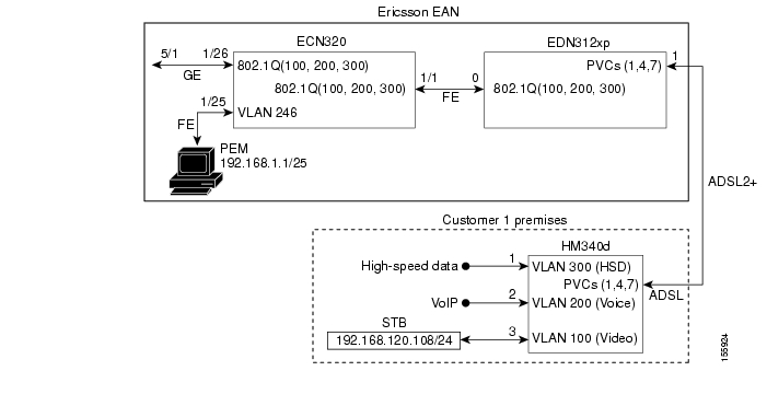
Figure C-1 illustrates an example network of Ericsson DSL equipment. A Public Ethernet Manager (PEM) terminal communicates with an Ethernet Controller Node (here an ECN320), which in turn aggregates traffic from one or more Ethernet DSLAM Nodes (here an EDN312xp DSLAM). The DSLAM, in turn, communicates with an HM340d home access gateway (HAG).
Table C-1 lists the VLANs, their descriptions, and addresses for the ECN320 and EDN312xp DSLAM. Table C-2 lists the configuration parameters for the HM340d.
Figure C-1 Example Ericsson Network
Table C-2 HM340d Configuration Parameters
HSD
300
0
1
8
35
LLC
UBR
—
—
—
VoIP
200
1
4
0
51
CBR
—
300
—
Video
100
2
7
8
59
VBR-RT
1200
600
10
1 Permanent virtual connection
2 Virtual path identifier
3 Virtual connection identifier
4 Peak cell rate
5 Sustained cell rate
6 Maximum burst size
Hardware and Software Versions
Table C-3 lists the hardware and software versions for the Ericsson equipment.
Configuring Ericsson Components
The following tasks are presented in the general order in which they should occur:
•
•
•
Configuring the Switch
To configure the Ericsson ECN320 switch, use Hyperterminal or a similar application to set parameters as follows:
To save the completed configuration, use the following command:
config save-configuration
Configuring the DSLAM
To configure the access network on the EDN312xp DSLAM, use Ericsson's Network Configuration Manager Application and set parameters as follows:
Network > Line Terminations and Regions
Region
Region Name = Root
Network Elements >
DHCP Server
Name = DHCPServer
Region = (root)
Lease Time = 11520
Domain File Server
IP addr = 192.168.1.1
FTP User = ftpuser
FTP PW = ericsson
Remote Storage Login = eda-mp
Remote Storage PW = ericsson
Region = (root)
NTP Server
IP addr = 192.168.1.1
PEM1 Domain Service
IP addr = 192.168.1.1
Region = (root)
Networks >
IP Network
ID = 192.168.1.0
Mask = 255.255.255.0
GW = 192.168.1.20
Max Ethernet Frame Size = 1526
Domain Subnets
Name = Subnet1
DHCP Server = DHCPServer
Domain File Server = 192.168.1.1
PEM Domain Service = DomainService
NTP Server = 192.168.1.1
IP Ranges
Network ID = 192.168.1.0
Network Mask = 255.255.255.0
Lower Limit = 192.168.1.50
Upper Limit = 192.168.1.100
1 Public Ethernet Manager, Ericsson's DSLAM configuration application.
Note
Configuring the HAG
Two files are used to configure the Ericsson HM340d HAG:
•
•
Note
Because the HAG configuration files used in the solution are not the Ericsson defaults, you must edit the default files to configure the HAG to forward the three VLANs and services. This information is part of the DSLAM service configurations, and must also be included in the HAG configuration.
Note
Edit the default files to conform to the following.
atm.conf
The following shows the atm.conf file used for both user profiles.
# atm.conf -- ATM PVC configuration# Each line in this file will result in a ATM PVC being configured, and on this PVC ethernet frames will be bridged (RFC 2684).# ATM PVC Interface number 0 (zero) is the management PVC.PVC VPI VCI Encap Service Class Parms----------------------------------------------------------0 12 35 llc nrtvbr 300 150 101 8 35 llc ubr2 0 35 llc ubr3 0 43 llc ubr_pcr 6004 0 51 llc cbr 3005 8 51 llc nrtvbr 600 300 106 8 43 llc rtvbr 600 300 107 8 59 llc rtvbr 1200 600 10bridge.conf
The following shows the bridge.conf file used for Profile1.
# bridge.conf -- virtual/software ethernet bridge configuration# The information in this file determines which logical ethernet bridges should be present.# Each line is a bridge with the members as a space-separated list, were each member is either a PVC or a tagged or untagged ethernet port. A PVC member is listed as "pvcN" where N is the ATM PVC identifier from the /etc/atm.conf configuration file. An untagged port member is listed as "portN", and a tagged port as "tagged-portN", were N is the port number (0-3, inclusive).Each logical port (PVC, tagged or untagged ethernet port) may only be a member of one bridge. If one untagged port (for example "port2") is used, the corresponding tagged port ("tagged-port2") may not be used, and vice versa.# VLAN id Members300 port0 pvc1100 port2 pvc7200 port1 pvc4The following shows the bridge.conf file used for Profile2. Note the addition of port 3.
# bridge.conf -- virtual/software ethernet bridge configuration# The information in this file determines which logical ethernet bridges should be present.# Each line is a bridge with the members as a space-separated list, were each member is either a PVC or a tagged or untagged ethernet port. A PVC member is listed as "pvcN" where N is the ATM PVC identifier from the /etc/atm.conf configuration file. A untagged port member is listed as "portN", and an tagged port as "tagged-portN", were N is the port number (0-3, inclusive).Each logical port (PVC, tagged or untagged ethernet port) may only be a member of one bridge. If one untagged port (for example "port2") is used, the corresponding tagged port ("tagged-port2") may not be used, and vice versa.# VLAN id Members300 port0 pvc1100 port2 port3 pvc7200 port1 pvc4Creating Line Configurations
Line configurations are required to establish communication between the DSLAM and the HAG. A separate line configuration is used be each profile.
Using the Ericsson PEM configuration application, choose Service Configuration > DSL Line, and set (or confirm) parameters are as follows:
Creating Services and Profiles
Using the PEM configuration application, create services and user profiles for video, voice, and data. These services create the bridge between the Ethernet VLAN services for video, voice and data and the ATM PVC (VPI/VCI pairs).
Creating Services and Profiles for Video
Creating a Video Service
To create a video service using the Ericsson PEM configuration application, choose Service Configuration > Action > Create New, and set (or confirm) parameters as follows:
Creating Video Bandwidth Profiles
Create two different bandwidth configurations (profiles) for video. These can be applied to the video service configuration depending on the profile the user is using.
To create video bandwidth profiles using the Ericsson PEM configuration application, choose Service Configuration > Video > Bandwidth > Create, and set parameters as follows:
1
Name
VideoLowBW
PCR Down/Up
6016/512
SCR Down/Up
5014/128
MBS Down/Up
30/30
2
Name
VideoBW
PCR Down/Up
10016/512
SCR Down/Up
10016/128
MBS Down/Up
30/30
Creating Services and Profiles for Voice
Creating a Voice Service
To create a voice service using the Ericsson PEM configuration application, choose Service Configuration > Action > Create New, and set (or confirm) parameters as follows:
Creating a Voice Bandwidth Profile
Create a single bandwidth configuration (profile) for voice. This can be applied to the voice service configuration for both Profile 1 and Profile 2.
To create video bandwidth profiles using the Ericsson PEM configuration application, choose Service Configuration > Voice > Bandwidth > Create, and set parameters as follows:
Creating Services and Profiles for Data
Creating a Data Service
To create a data service using the Ericsson PEM configuration application, choose Service Configuration > Action > Create New, and set (or confirm) parameters as follows:
Note
Creating Data Bandwidth Profiles
Create two different bandwidth configurations (profiles) for data. These can be applied to the data service configuration depending on the profile the user is using.
To create video bandwidth profiles using the Ericsson PEM configuration application, choose Service Configuration > Data > Bandwidth > Create, and set parameters as follows:
1
Name
DataLowBW
PCR Down/Up
1152/512
SCR Down/Up
N/A
MBS Down/Up
N/A
2
Name
DataBW
PCR Down/Up
1728/512
SCR Down/Up
N/A
MBS Down/Up
N/A
Creating User Profiles and Adding Services
Line and service configurations must be completed before you can user profiles.
The following tasks use the Ericsson PEM configuration application to create two user profiles and add video, voice, and data services.
Creating Profile 1
Do the following to create Profile 1 and add services.
Step 1
a.
b.
c.
d.
Step 2
a.
b.
c.
d.
e.
Note
Step 3
a.
b.
c.
d.
e.
Step 4
a.
b.
c.
Note
d.
EAN Name: ECN320-192-168-1-100
MDF Position: 1.0.1
e.
Note
Creating Profile 2
Do the following to create Profile 2 and add services.
Step 1
a.
b.
c.
d.
Step 2
a.
b.
c.
d.
e.
Step 3
a.
b.
c.
d.
e.
Step 4
a.
b.
c.
Note
d.
EDN Name: ECN320-192-168-1-100
MDF Position: 1.0.2
e.
Note
Creating an IP Filter
If a static IP address is used as part of a video, voice, or data service configuration, an IP filter must be applied for the static IP address to work. Ericsson does not provide a default filter that allows all addresses in the downstream direction to be passed through to the HAG. At least one IP address must be entered into the filter, with that IP address to be marked as "allow" or "deny." Because the range command is not supported in the filter configuration in the downstream direction, each address through which traffic is allowed to pass must be entered individually into the filter.
A workaround is to create a filter that denies only one IP address in the downstream direction. The IP address to deny can be any IP address that will not be used to send to, or receive from, the HAG attached to the DSLAM line port for this service configuration. This solution is easier than attempting to add all the IP addresses of all devices that will be sending to, or receiving from, the device attached to the port of the HAG.
Do the following to create an IP filter.
Step 1
Step 2
Step 3
Step 4
a.
b.
c.
d.
Step 5
a.
b.
c.
d.
Step 6
Special Issues
Note the following special issues:
1.
2.
![]()
![]()
![]()
![]()
![]()
![]()
![]()
![]()
Posted: Mon Jun 12 11:25:16 PDT 2006
All contents are Copyright © 1992--2006 Cisco Systems, Inc. All rights reserved.
Important Notices and Privacy Statement.