|
|

This chapter describes SESM deployment options. It includes the following topics:
This section provides an overview of an SESM deployment and how it fits into a network access provider (NAP) or Internet service provider (ISP) communication network.
Subscribers can access the Cisco SESM portal over any access technology, including wireless LAN, fixed wireless, leased line, DSL, and GPRS, with any Web browser on a variety of devices, including Wireless Access Protocol (WAP) phones, personal digital assistants (PDAs), and desktops.
A default network is an IP address or subnet that TCP packets can access without authentication. The SESM web applications and their associated J2EE web servers run in the default network. The default network is configured on the Service Selection Gateway (SSG).
An SESM solution works with the Cisco Service Selection Gateway (SSG), a feature set embedded in the Cisco IOS broadband release train. Some of the devices on which the SSG can run include the Cisco 7200 Series high-performance multifunction router, the Cisco 7400 Series router, and the Cisco 6400 Universal Access Concentrator.
Figure 2-1 is a general network diagram showing SESM components, SSGs, and a default network.
Although the figure shows all of the access technologies and three different SSG devices all using the same default network, such a deployment would not be typical. A more typical deployment might consist of several routers of the same type, each one with its own default network. SESM would be deployed on each of the default networks.
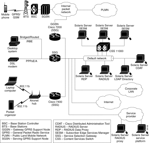
Regardless of the type of modem or connection layer protocol a subscriber uses, all TCP packets are routed by the SSG when the SSG is enabled. Physically, the TCP traffic passes through the SSG on its way to SESM. Logically the HTTP traffic flows directly to an SESM portal application running on a default network.
An SESM web portal application is highly scalable. You can start and stop instances of SESM portal applications without affecting subscribers. This is because an SESM portal application is completely stateless. It does not store any subscriber session information. Rather, the portal application queries SSG for session state information.
Production deployments might include multiple instances of J2EE web servers and associated SESM portals on the default network. For production deployments, we recommend using enterprise-class server systems with hot-swappable components and load-balancing across the multiple servers. The Domain Name System (DNS) resolves host names for any of the SESM portal applications to the IP address of the load balancer. The Cisco Content Services Switch 11000 (CSS 11000) is preferred for load balancing.
This section provides some examples of how a subscriber gains access to an SESM portal application.
1. The subscriber launches the PPP client.
2. The TCP packet travels to a Cisco router device which has SSG enabled.
3. The SSG authenticates the PPP user.
4. The subscriber launches a web browser and sends an HTTP message.
5. The TCP packet containing the first HTTP request travels through the SSG to the SSG's default network, and then to the J2EE web server and the SESM portal application.
6. If the SESM single sign-on feature for PPP subscribers is enabled, the user is already authenticated and SESM does not request an additional authentication. Rather, SESM queries the SSG for the subscriber's cached profile. A session is established, and SESM returns the subscriber's home page with a list of authorized services.
7. If the SESM single sign-on feature is disabled, SESM returns the SESM logon page. When this request reaches an SESM web application, the application requests authentication services from the SSG. After the subscriber is authenticated, an SESM session is established.
This example describes the connection sequence for routed access to SESM. For example, consider a subscriber using a WAP-enabled phone configured for access through a WLAN access point.
1. The subscriber launches a web browser and sends an HTTP message.
2. The TCP packet containing the first HTTP request travels through the SSG, to the SSG's default network, and then to the J2EE web server and the SESM portal application.
3. The SESM portal application returns the SESM logon page.
4. When the SESM portal application receives the subscriber's logon information, it requests authentication services from the SSG. After the subscriber is authenticated, an SESM session is established.
This section describes an SESM deployment in RADIUS mode. It includes the following topics:
Figure 2-2 shows a simplified view of the SESM deployed in RADIUS mode and the communication mechanisms used between the various software components.
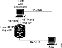
SSG and the SESM portal application work together to process subscriber requests.
1. SSG authenticates a subscriber based on a subscriber profile stored in the AAA server.
2. The SESM portal application obtains the list of authorized services for a subscriber from the subscriber profile in the AAA server.
3. After the subscriber selects a service, SSG makes the connection to the service based on information in service profiles stored in the AAA server.
4. If the subscriber profile indicates automatic connections for some services, SSG makes the connection to those services immediately after authentication, rather than waiting for the subscriber to select the service from the SESM portal.
Table 2-1 describes the roles of an SESM portal application and SSG in processing typical subscriber actions in a RADIUS deployment.
| Subscriber Action | Software Activity | Components Involved |
|---|---|---|
Subscriber logs on | Authenticate the subscriber in the system. | The SESM portal initiates authentication by sending a message to SSG, using the RADIUS protocol. SSG forwards the RADIUS message to the RADIUS server. The RADIUS server authenticates the subscriber and returns a message containing information from the subscriber profile. SSG creates an internal host object that represents the subscriber in the current session and forwards the message to the SESM portal. |
Display web interface containing customized content appropriate for the logged on subscriber. | The RADIUS message contains the subscriber profile as stored in the RADIUS database. The SESM portal can analyze the subscriber profile and send appropriate content accordingly. | |
Display the list of services that the subscriber is currently authorized to access. | The RADIUS message contains the list of services from the subscriber profile. Authorization is implied for all services in the list. The SESM portal obtains a service profile directly from the RADIUS server for each service in the list. | |
Subscriber selects a service | The SESM portal sends a connection request to SSG. SSG creates a connection object, connecting the host object to the service. When the service is connected, SSG creates a service object. SSG then switches traffic from that subscriber to the requested service. | |
Subscriber selects a second service | Access a second service, without reauthentication. | The SESM portal sends the request to the SSG. SSG creates a second connection object and service object. Both services are concurrently accessed. |
Subscriber deselects a service | The SESM portal sends the request to the SSG. SSG destroys the appropriate connection object. |
Table 2-2 summarizes the steps required to deploy the SESM in RADIUS mode.
| Deployment Step | References |
|---|---|
1. Install and configure a RADIUS AAA server. | "Configuring RADIUS" and documentation from the RADIUS server vendor |
2. Ensure that the SSG host device is running an appropriate Cisco IOS software release. For SESM Release 3.1(3), this is Cisco IOS Release 12.2(4)B or later. | SSG documentation1 |
3. Configure SSG. Use Cisco IOS commands on the SSG host device to: |
SSG documentation1 |
4. Install and configure the SESM portal application and J2EE-compliant web server. | |
5. Create user and service profiles in the RADIUS database. | "Configuring RADIUS" and documentation from the RADIUS server vendor |
| 1See the "Related Documentation" section for a link to the online version of SSG documentation. |
This section describes an SESM deployment in LDAP mode. It includes the following sections:
Figure 2-3 shows a simplified view of the SESM deployed in LDAP mode and the communication mechanisms used between the various software components.
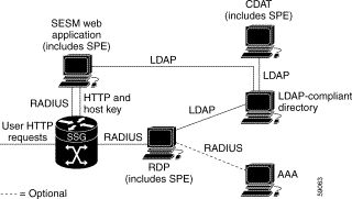
The optional AAA server might provide the following services:
In an LDAP mode deployment, the Cisco Subscriber Policy Engine (SPE) Version 1.01 provides services to the SESM portal application, CDAT, and RDP. To install SPE services, install the LDAP component from the SESM installation package. This guide describes how to install and configure SPE to work with SESM components.
For more information about SPE, including its logical relationship to SESM components, see the "Introduction to Cisco SPE" section.
Table 2-3 describes the role of the SESM applications and SSG in processing typical subscriber actions in an LDAP deployment.
| Subscriber Action | Software Activity | Components Involved |
|---|---|---|
Subscriber logs on | Authenticate the user in the system. | The SESM portal application initiates authentication by sending a RADIUS message to SSG. SSG forwards the RADIUS message to the RDP. The RDP can authenticate using RADIUS or the LDAP directory, depending on how the RDP is configured:
The response is returned to the SESM portal application following the same path as described above. SSG creates an internal host object that represents the subscriber in the current session. |
Display appropriate web pages to user. | After the subscriber is authenticated, the SESM portal application uses the SPE API to retrieve a subscriber profile from the LDAP directory. The SESM portal can analyze the profile and display appropriate web pages. | |
Display the list of services in the subscriber's profile. | The SESM portal application uses the SPE API to retrieve service profiles from the LDAP directory for each service in the list. | |
Subscriber selects a service | SSG sends an authorization request to RDP. Regardless of the RDP mode, RDP always uses the SPE API to send service authorization requests to the LDAP directory. If the service is authorized, SSG creates an internal connection object, connecting the host object to the service. When the service is connected, SSG creates a service object. SSG then switches traffic from that subscriber to the requested service. | |
Subscriber selects a second service | Access a second service without reauthentication. | SSG sends another authorization request to RDP. Regardless of its mode, RDP always uses the SPE API to send service authorization requests to the LDAP directory. If the service is authorized, SSG creates a second connection object and service object. Both services are concurrently accessed. |
Subscriber updates an e-mail address | Update the LDAP directory. | The SESM portal application sends the update to the directory using the SPE API. |
Subscriber creates a subaccount | Update the LDAP directory. | The SESM portal application sends the update to the directory using the SPE API. |
Subscriber deselects a service | Terminate access to the service. | The SESM portal application sends the request to the SSG. SSG destroys the appropriate connection object. |
Table 2-4 summarizes the installation and configuration activities for SESM in LDAP mode.
| Activity | Reference |
|---|---|
1. (Optional) Install and configure a RADIUS server if: | "Configuring RADIUS" and documentation from the RADIUS server vendor |
2. Ensure that the SSG host device is running an appropriate Cisco IOS software release. For SESM Release 3.1(3), this is Cisco IOS Release 12.2(4)B or later. | SSG documentation1 |
3. Configure SSG. Use Cisco IOS commands on the SSG host device to: |
SSG documentation1 |
4. Install and configure an LDAP directory. | LDAP Directory Configuration Requirements Documentation from the directory vendor |
5. Install and configure the SESM software components, which include: the SESM portal application, a J2EE-compliant web server, RDP, SPE, and CDAT. | |
6. Load sample data and create roles, groups, and user and service profiles in the LDAP directory. | Cisco Distributed Administration Tool Guide |
| 1See the "Related Documentation" section for a link to the online version of SSG documents. |
![]()
![]()
![]()
![]()
![]()
![]()
![]()
![]()
Posted: Mon Aug 26 08:41:12 PDT 2002
All contents are Copyright © 1992--2002 Cisco Systems, Inc. All rights reserved.
Important Notices and Privacy Statement.