|
|

Table Of Contents
Checking the Network Summary Page
Adding a Cisco Wireless LAN Controller to Cisco WCS
Creating an RF Calibration Model
Adding a Campus Map to the Cisco WCS Database
Adding a Standalone Building to the Cisco WCS Database
Adding an Outdoor Area to a Campus
Adding Floor Plans to a Campus Building
Adding Floor Plans to a Standalone Building
Adding Access Points to Floor Plan and Outdoor Area Maps
Monitoring WLANs with Cisco WCS
Detecting and Locating Rogue Access Points
Acknowledging Rogue Access Points
Pinging a Network Device from a Controller
Viewing Current Controller Status and Configurations
Viewing Cisco WCS Statistics Reports
Using Cisco WCS to Update System Software
Managing Cisco WCS and the Cisco WCS Database
Updating the Cisco WCS for Windows
Reinitializing the Cisco WCS for Windows Database
Reinitializing the Cisco WCS for Linux Database
Administering Cisco WCS Users and Passwords
Using Cisco WCS
This chapter describes how to use the Cisco Wireless Control System (WCS). This chapter contains these sections:
•
Checking the Network Summary Page
•
•
•
•
•
Checking the Network Summary Page
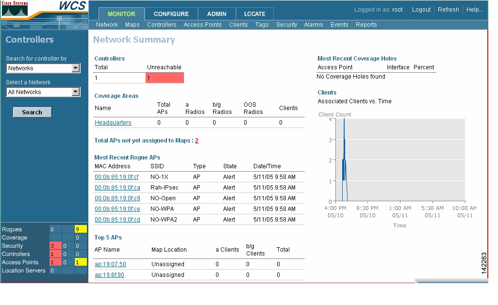
When you use Cisco WCS for the first time, the Network Summary page shows that the Cisco Wireless LAN Controllers, Coverage Areas, Most Recent Rogue Access Points, Top Five Cisco 1000 Series lightweight access points, and the Most Recent Coverage Holes database is empty. It also shows that no client devices are connected to the system. After you configure the Cisco WCS database with one or more controllers, the Network Summary page shows that the controllers, Coverage Areas, Most Recent Rogue Access Points, the Top Five lightweight access points, and the Top Five Coverage Holes databases are updated. Figure 9-1 shows a typical Network Summary page.
Figure 9-1 Network Summary Page
Adding a Cisco Wireless LAN Controller to Cisco WCS
When you know the IP address of controller service port or controller name, follow the steps in this section to add the controller to the Cisco WCS database.
Note
Step 1
Step 2
Step 3
Step 4
Step 5
If Cisco WCS does not find a controller at the IP address that you entered for the controller, the Discovery Status dialog displays this message: No response from device, check SNMP. Check these settings to correct the problem:
•
•
•
Step 6
Creating an RF Calibration Model
When you use Cisco WCS with Location Services and you need to improve client and rogue access point location accuracy across one or more floors of a building, you can create an RF Calibration Model that uses manually-collected RF measurements to calibrate the location algorithm.
When you have multiple floors in a building with the same physical layout as the calibrated floor, you can save time calibrating the remaining floors by applying the same RF Calibration Model to the remaining floors.
Follow the RF Calibration procedures included in the Cisco WCS Web Interface Online Help to create an RF Prediction Model.
Using Maps
This section describes how to add, change, and use maps in the Cisco WCS database. These sections explain how to work with maps in Cisco WCS:
•
•
•
•
•
•
•
•
Adding a Campus Map to the Cisco WCS Database
When you add maps to Cisco WCS, you can view your managed system on realistic campus, building, and floor plan maps. This section describes how to add a single campus map to the Cisco WCS database.
Step 1
Step 2
Step 3
Step 4
Step 5
Step 6
Step 7
Step 8
Step 9
Step 10
Adding a Building to a Campus
You can add buildings to the Cisco WCS database whether or not you have added maps or campuses to the database.
Follow these steps to add a building to a campus in the Cisco WCS database:
Step 1
Step 2
Step 3
Step 4
Step 5
a.
b.
c.
d.
Tip
e.
f.
g.
Adding a Standalone Building to the Cisco WCS Database
Follow these steps to add a standalone building to the Cisco WCS database:
Step 1
Step 2
Step 3
Step 4
a.
b.
c.
d.
e.
Adding an Outdoor Area to a Campus
You can add outdoor areas to a campus in the Cisco WCS database whether or not you have added outdoor area maps to the database. Follow these steps to add an outdoor area to a campus:
Step 1
Step 2
Step 3
Step 4
Step 5
Step 6
Step 7
Step 8
Step 9
a.
b.
c.
d.
Tip
e.
f.
g.
Adding Floor Plans to a Campus Building
After you add a building to a campus you can add individual floor plan and basement maps to the building. Follow these steps to add floor plans to a building:
Step 1
Note
Step 2
Step 3
Step 4
Step 5
Step 6
Step 7
Step 8
Step 9
a.
b.
c.
d.
e.
f.
g.
Tip
h.
Step 10
Using the Map Editor
You use the Cisco WCS Map Editor to define, draw, and enhance floor plan information. The map editor allows you to create obstacles so that they can be taken into consideration while computing RF prediction heatmaps for access points. You can also add coverage areas for location appliances that locate clients and tags in that particular area. Follow these steps to use the map editor:
Step 1
Step 2
Step 3
Step 4
Step 5
Adding Floor Plans to a Standalone Building
After you have added a standalone building to the Cisco WCS database you can add individual floor plan maps to the building. Follow these steps to add floor plan maps to a building:
Step 1
Note
Step 2
Step 3
Step 4
Step 5
Step 6
Step 7
Step 8
a.
b.
c.
d.
e.
f.
g.
h.
Tip
i.
Step 9
Adding Access Points to Floor Plan and Outdoor Area Maps
After you add the .FPE and/or .PNG, .JPG, or .GIF format floor plan and outdoor area (coverage area) maps and controllers to the Cisco WCS database, you can position lightweight access point icons on the maps to show where they are installed in the buildings. Follow these steps to add access points to maps:
Step 1
Step 2
Step 3
Step 4
Step 5
Step 6
Step 7
Step 8
Note
Figure 9-2 shows a first-order RF prediction map. In this example, AP1 and AP3 are set to 90 degrees and AP2 is set to 0 degrees, so the three access points provide maximum coverage for the inside of the building and not the loading dock.
Also note that this display is only an approximation of the actual RF signal intensity, because it does not take into account the attenuation of various building materials, such as drywall or metal objects, nor does it display the effects of RF signals bouncing off obstructions.
Figure 9-2 First-Order RF Prediction Map
Step 9
Step 10
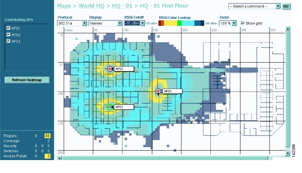
Figure 9-3 shows a second-order RF prediction. In this example, AP1 is set to 0 degrees, and AP2 and AP3 are set to 90 degrees, so the three access points provide maximum coverage for the right wing of the building. The access points in this prediction cover a smaller area because of the wall attenuation factored in by the RF prediction algorithm.
Figure 9-3 Second-order RF Prediction
Note
Monitoring Maps
These sections describe how to use maps to monitor your WLANs:
Monitoring Predicted Coverage (RSSI)
Follow these steps to monitor the predicted WLAN coverage on a map:
Step 1
Step 2
Step 3
Step 4
•
•
•
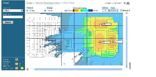
Figure 9-4 shows a typical RF prediction heat map with access points covering one end of a building.
Figure 9-4 RF Prediction Heat Map
Monitoring Channels on a Floor Map
Follow these steps to monitor channels on a floor map:
Step 1
Step 2
Step 3
Step 4
Monitoring Transmit Power Levels on a Floor Map
Follow these steps to monitor transmit power levels on a floor map:
Step 1
Step 2
Step 3
Step 4
•
•
•
•
•
The power levels and available channels are defined by the country code setting and are regulated on a country by country basis. Refer to the Country Code appendix for the maximum transmit power levels for each country.
Monitoring Coverage Holes on a Floor Map
Coverage holes are areas where clients cannot receive a signal from the wireless network. When deploying wireless networks, there is a trade-off between the cost of the initial network deployment and the percentage of coverage hole areas. A reasonable coverage hole criterion for launch is between 2 and 10 percent. This means that between two and ten test locations out of 100 random test locations might receive marginal service. After launch, the Cisco WLAN Solution Radio Resource Management (RRM) identifies these coverage areas and reports them to the IT manager, allowing the IT manager to fill holes based on user demand.
Follow these steps to monitor coverage holes on a floor map:
Step 1
Step 2
Step 3
Step 4
Step 5
Monitoring Users on a Floor Map
Follow these steps to monitor client devices on a floor map:
Step 1
Step 2
Step 3
Step 4
Monitoring WLANs with Cisco WCS
The se sections describe how to use Cisco WCS to monitor your WLANs:
•
•
Detecting and Locating Rogue Access Points
When the lightweight access points on your WLAN are powered up and associated with controllers, Cisco WCS immediately starts listening for rogue access points. When a controller detects a rogue access point, it immediately notifies Cisco WCS, which creates a rogue access point alarm.
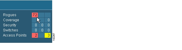
When Cisco WCS receives a rogue access point message from controller, an alarm indicator appears in the lower left corner of all Cisco WCS user interface pages. The alarm indicator in Figure 9-5 shows 72 rogue access point alarms.
Figure 9-5 Alarm Indicator for Rogue Access Points
Click the Rogues indicator to display the Rogue AP Alarms page. The Rogue AP Alarms page lists the severity of the alarms, the rogue access point MAC addresses, the rogue access point types, the owners (WCS operators), the date and time when the rogue access points were first detected, the channel numbers they are broadcasting on, and their SSIDs.
Also on this page, you can highlight one or more entries by checking the desired check boxes and apply the following commands to all selected rogue access point alarms: Assign to me, Unassign, Delete, Clear, or configure Email Notification.
To see more rogue access point information, click any Rogue MAC Address link to display the associated Alarms > Rogue AP MAC address page.
The Alarms > Rogue AP MAC address page shows detailed information about the rogue access point alarm, and allows you to modify the rogue access point alarm with these commands:
•
•
•
•
•
•
•
•
•
On the Alarms > Rogue AP MAC address page, select Map to display the current calculated rogue access point location on the Maps > Building name > Floor name page. If you are using Cisco WCS with Location, Cisco WCS compares RSSI signal strength from two or more access points to find the most probable location of the rogue access point, and places a small skull-and-crossbones indicator at its most likely location. The Cisco WCS Base (that is, without Location) function relies on RSSI signal strength from the rogue access point, and places a small skull-and-crossbones indicator next to the access point receiving the strongest RSSI signal from the rogue unit. Figure 9-6 shows a map that indicates a rogue unit's location.
Figure 9-6 Map Indicating Location of Rogue Unit
Acknowledging Rogue Access Points
To acknowledge known rogue access points, navigate to the Rogue AP Alarms page. Right-click the rogue access point (red, unknown) to be acknowledged, and select Set State to `Known Internal' or Set State to `Known External'. In either case, Cisco WCS removes the red rogue access point entry from the Alarms page.
Locating Clients
You can use Cisco WCS to locate clients on your WLAN. Follow these steps to locate clients:
Step 1
Step 2
Step 3
Step 4
•
•
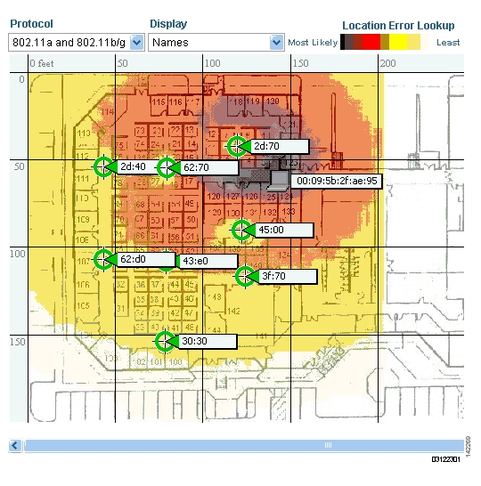
If you are using Cisco WCS with Location, Cisco WCS compares RSSI signal strength from two or more access points to find the most probable location of the client, and places a small laptop icon at its most likely location. The Cisco WCS Base (that is, without Location) function relies on RSSI signal strength from the client, and places a small laptop icon next to the access point that receives the strongest RSSI signal from the client. Figure 9-7 shows a heat map that includes client locations.
Figure 9-7 Map With Client Locations
Finding Coverage Holes
Coverage holes are areas where clients cannot receive a signal from the wireless network. The Operating System Radio Resource Management (RRM) identifies these coverage hole areas and reports them to Cisco WCS, allowing the IT manager to fill holes based on user demand. Follow these steps to find coverage holes on your WLANs:
Step 1
Step 2
Step 3
Step 4
Pinging a Network Device from a Controller
Follow these steps to ping other devices from a controller:
Step 1
Step 2
Step 3
Step 4
Step 5
Cisco WCS displays the Ping Results window showing the packets sent and received. Click Restart to ping the network device again, or click Close to stop pinging the network device and close the Ping Results window.
Viewing Current Controller Status and Configurations
After you add controllers and lightweight access points to the Cisco WCS database you can view the Cisco WLAN Solution status. To view the system status, click the Monitor tab and select Network to display the Network Summary page. Figure 9-8 shows the Network Summary page.
Figure 9-8 Network Summary Page
Viewing Cisco WCS Statistics Reports
Cisco WCS periodically collects statistics such as RSSI, SNR, profile failures, client counts, rogue access point trend, and busy clients, and organizes them into reports. To view these reports, use the Monitor > Reports pages.
Using Cisco WCS to Update System Software
Follow the steps in this section to update controller (and access point) software using Cisco WCS.
Note
Step 1
When you are downloading through a 2000, 4100, or 4400 controller DS (Distribution System) network port, the TFTP server can be on the same or a different subnet, because the DS port is routable.
Step 2
Step 3
Step 4
Step 5
Step 6
Be sure you have to correct software file for your controller:
•
•
•
Step 7
Managing Cisco WCS and the Cisco WCS Database
This section describes how to manage Cisco WCS and its database. This section contains these sections:
•
•
•
•
•
Installing Cisco WCS
Refer to the Windows Cisco WCS Quick Start Guide or the Linux Cisco WCS Quick Start Guide for instructions on installing Cisco WCS on a server.
Updating the Cisco WCS for Windows
Follow these steps to upgrade Cisco WCS for Windows:
Step 1
Step 2
Step 3
Step 4
Step 5
Step 6
Backup Succeeded. You may restart the Cisco WCS Server now.Step 7
Step 8
Step 9
Note
Step 10
Step 11
Step 12
Step 13
Restore Succeeded. You may restart the Cisco WCS Server now.If you receive an error message, scroll down the page to find the error. Normally, the only error that will halt a backup is if an incorrect directory is specified; if this is the case, repeat this procedure with the correct directory to complete the backup.
Updating Cisco WCS for Linux
Follow these steps to upgrade Cisco WCS for Linux:
Step 1
Step 2
Step 3
Step 4
Step 5
Step 6
Step 7
Step 8
Step 9
Backup Succeeded. You may restart the Cisco WCS Server now.Step 10
Step 11
Step 12
Step 13
Step 14
Step 15
Step 16
You may restart the Cisco WCS Server now.Step 17
Step 18
Wireless Control System Server is up. Please connect your clients (Cisco WCS User
Interfaces) using Http Port: 80 or Https Port: 433.
Reinitializing the Cisco WCS for Windows Database
You only have to reinitialize the Cisco WCS for Windows database when the Cisco WCS database becomes corrupted.
Note
Follow these steps to reinitialize the Cisco WCS for Windows database:
Step 1
Step 2
Step 3
Step 4
Step 5
Do you want to Reinitialize Web NMS?The startdb.bat window displays many accomplished messages. When the Cisco WCS database is reinitialized, the Reinitialize Web NMS Database window reappears.
Step 6
Successfully reinitialized the Database.The Reinitialize Web NMS Database window closes, and the startdb.bat window displays this message:
Press any key to continue.Step 7
Reinitializing the Cisco WCS for Linux Database
You only have to reinitialize the Cisco WCS for Linux database when the Cisco WCS database becomes corrupted.
Note
Step 1
Step 2
Step 3
Administering Cisco WCS Users and Passwords
This section describes how to add user accounts and assign them to a user group, change passwords, and delete user accounts using the Cisco WCS administration function. Cisco WCS supports four user groups:
•
•
•
•
Adding WCS User Accounts
Follow these steps to add user accounts to WCS:
Step 1
Note
Step 2
Step 3
Step 4
Step 5
Step 6
Step 7
Step 8
Step 9
Changing Passwords
Follow these steps to change the password on a user account:
Step 1
Step 2
Step 3
Step 4
Step 5
Step 6
Step 7
Deleting User Accounts
Follow these steps to delete a user account:
Step 1
Step 2
Step 3
Step 4
Warning! On deleting this user you would no longer be able to log on with this user name,
are you sure you want to do this?
Step 5
Step 6
Step 7
![]()
![]()
![]()
![]()
![]()
![]()
![]()
![]()
Posted: Thu Sep 15 08:50:43 PDT 2005
All contents are Copyright © 1992--2005 Cisco Systems, Inc. All rights reserved.
Important Notices and Privacy Statement.