|
|

Table Of Contents
Configuration and Ordering Guide
Mounting Bracket Kit for Power Feed Panel
Customer-Provided Components and Accessories
Wireless Transverters and Duplexers
Manufacturers or Suppliers for Accessories
Configuration and Ordering Guide
Introduction
After site planning has been completed, use the information in this section to determine exactly what equipment and accessories you need to order.
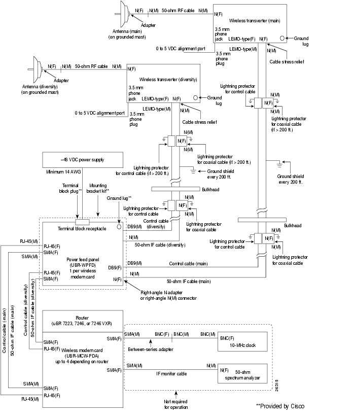
Figure A-1 shows all major components and accessories needed to install your broadband fixed wireless system. Refer to this diagram to determine which items are required for your installation. Some of the items are included with the major components and some must be ordered from Cisco or a third-party vendor.
Ordering Notes
These are basic configuration facts that should be taken into consideration when determining the equipment to order:
•
Each combination of one wireless modem card and one power feed panel will support one end
of only one point-to-point link. Each end of a link may consist of one wireless transverter and
one antenna, or two wireless transverters and two antennas. When there are two transverters
and two antennas, the first transverter-antenna set supports the main signal, and the second transverter-antenna set supports the diversity signal.•
•
•
Note
Figure A-1 Wireless Broadband Router System
Cisco-Provided Accessories
Cisco provides the accessories described in this section to help in the installation of your wireless broadband router system. These items can be found in the equipment and accessory cartons.
Mounting Bracket Kit for Power Feed Panel
This kit contains brackets for installing the power feed panel in a 19-inch rack or attaching it to a wall. It contains the fasteners necessary for attaching the brackets to the unit. Instructions for attaching these brackets and installing the power feed panel can be found in the Cisco uBR7200 Series Wireless Modem Card and Subsystem Installation and Configuration document.
Pluggable Terminal Block
This terminal block is used to wire the DC power supply to the power feed panel, and is inserted into a receptacle in the rear panel of the power feed panel. Instructions for wiring the DC power can be found in the Cisco uBR7200 Series Wireless Modem Card and Subsystem Installation and Configuration document.
Ground Lug Kit
A ground lug kit is provided for the power feed panel chassis. Instructions for using the ground lug kit can be found in the Cisco uBR7200 Series Wireless Modem Card and Subsystem Installation and Configuration document or Cisco Broadband Fixed Wireless System Power Feed Panel Replacement Instructions.
Customer-Provided Components and Accessories
The following additional items are required to install your wireless broadband router system. For each type of component or accessory required or suggested, types are listed.
Wireless Transverters and Duplexers
A wireless transverter (often referred to as the outdoor unit or ODU) is the control and data interface to the indoor router subsystems. It provides up/down conversion for IF-to-RF frequencies and power amplification. A duplexer is a fixed cavity waveguide module that fits in the transverter and provides channel plan-specific capability.
A wireless transverter and duplexer set is required for transmission for each wireless modem card. Two sets are required when using diversity.
Antennas
Antenna selection depends on your application. Refer to Chapter 2, "Site Planning Considerations," for information regarding antenna selection.
Power Supplies
A -48 VDC, 7A power supply is required to power each wireless transverter. If the wireless transverters are used for diversity, the power supply must be capable of delivering at least 14A at -48 VDC. The power supply must be wired to the power feed panel using 10 AWG (5.26 mm2) or larger wires, as required by local and national electrical codes.
Warning
Coaxial Cables
Use coaxial cables for the IF cable connections, the RF cable, and the monitor cable. If your installation includes 10-MHz clock, use a coaxial cable for this connection also.
Current Handling Capacity
The IF coaxial cables connecting the power feed panel to the transverter must be large enough to carry 12A short-circuit current at -48 VDC on the inner and outer conductors, as required by local and national electrical codes.
DC and RF Losses
DC resistance (sum of center conductor and outer conductor): 1.6 ohms maximum
RF loss at 420 MHz (the receive IF): 12 dB maximum
RF loss at 324 MHz (the transmit IF): 12 dB maximum
Table A-1 lists some of the coaxial cabling options with the maximum distance to the wireless transverter for each option.
* Assuming 1 dB total loss in connectors, power feed panel, and coaxial cable between line card and power feed panel
Connectors
Use the following connectors for coaxial cable:
•
•
•
Cisco strongly recommends that you use some type of cable-connection weatherproofing on all outdoor RF and IF cable connections to protect them against long-term degradation from weather effects. This is typically done by applying a suitable seal to the N-type connectors after they have been connected and verified. Do not use common electrical tape or similar types of tape because the resulting seal is not adequate, these types of tape do not withstand sunlight well, and they leave a gummy residue when removal becomes necessary.
There are several available products for this purpose. Some of the manufacturers/suppliers of these products are listed in Table A-2.
Control Cables
The control cables provide a physical connection for the RF subsystem control channel.
Use plenum-rated, shielded, CAT-5, indoor cable to connect the control channel port on the wireless modem card to the power feed panel. For the connection between the power feed panel and the transverter, use weatherized, plenum-rated, shielded CAT-5 cable.
Connectors
Use the following connectors for the control cables:
•
•
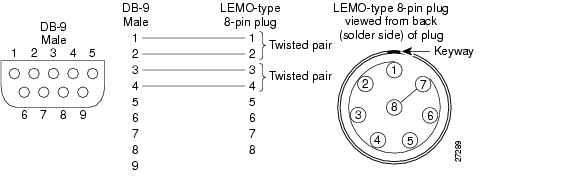
Figure A-2 DB-9 to 8-Pin LEMO-Type Wiring
Note
Lightning Protectors
Lightning protectors should be used on both cables, coaxial and control, connecting to the wireless transverter. They should be installed both before the bulkhead and near the transverter. Refer to Chapter 2, "Site Planning Considerations," for information regarding lightning protection.
Spare Equipment Planning
Cisco provides some of the parts and accessories for a typical wireless installation; however, many parts and accessories are obtained from other companies. The Cisco-provided parts and accessories include:
•
•
•
•
•
•
The Cisco-provided parts and accessories are normally available via standard Cisco return merchandise authorization (RMA) processes.
The non-Cisco-provided products must be obtained from other supplier(s). The replacement times for the non-Cisco-provided products will depend on the RMA procedures of the other supplier(s).
Cisco recommends that you design and maintain a spares inventory based on your network availability requirements.
Manufacturers or Suppliers for Accessories
Table A-2 provides information on some of the manufacturers or suppliers, including their web sites, of product offerings required to install a wireless system.
Note
![]()
![]()
![]()
![]()
![]()
![]()
![]()
![]()
Posted: Tue Aug 17 13:10:50 PDT 2004
All contents are Copyright © 1992--2004 Cisco Systems, Inc. All rights reserved.
Important Notices and Privacy Statement.