|
|

Product Number: UBR-WMF4A=
This document explains how to remove and replace the power feed panel component of a Cisco broadband fixed wireless multipoint headend system. The document includes instructions for powering down the system, removing an installed power feed panel, and
installing a new power feed panel.
 |
Note Use this document in conjunction with the Cisco uBR7200 Series Universal Broadband Router Hardware Installation Guide and Cisco uBR7200 Series Universal Broadband Router Software Configuration Guide, both of which shipped with your Cisco uBR7200 series router, and the Cisco uBR7200 Series Multipoint Wireless Modem Card and Subsystem Installation document that shipped with your point-to-multipoint wireless modem card. |
This document includes the following sections:
The Cisco IOS software running on your router contains extensive features and functionality. The effective use of many of these features is easier if you have more information. For additional information on configuring and maintaining the Cisco uBR7200 series router, the following documentation resources are available:
 |
Note You can access Cisco IOS software configuration documentation on the World Wide Web at http://www.cisco.com, http://www-china.cisco.com, or http://www-europe.cisco.com. |
The headend multipoint power feed panel provides as many as four multipoint wireless transverters with DC power, IF transmission signals, frequency reference, and control signals. The unit supplies the headend multipoint wireless modem card with IF reception signals. It contains four power/breaker switches for the power connections to four wireless transverters. (See Figure 1.)

The power feed panel consists of the following components:
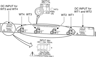
Figure 2 shows the front panel and Figure 3 shows the rear panel of the power feed panel. Table 1 describes the functions of the LEDs. Table 2 describes the functions of the connectors.

| LED | Function |
|---|---|
Power/breaker switch PWR ON | When on, indicates that power is available in that circuit. |
Wireless transverter PWR ON | When on, indicates that power is going to that transverter. |
| Connector | Type | Input/Output | Function |
|---|---|---|---|
MCW (4 on front panel) | SMA (female) | Input and Output | IF transmission signal, RF subsystem control signal, and 24-MHz reference signal from the wireless modem card. IF reception signal to the wireless modem card. |
INPUT (2 on rear panel) | Pluggable terminal block | Input | DC power source for the wireless transverters. (2 wireless transverters per DC power source) |
WT (4 on rear panel) | N-type (female) | Input and Output | IF transmission signal, -48V DC power, RF subsystem control signal, and 24-MHz reference signal to the transverter. IF reception signal from the transverter. |
This section provides a list of parts and tools that you need to remove and replace a multipoint headend power feed panel. This section also includes safety and ESD-prevention guidelines to help you avoid injury to yourself and damage to the equipment.
To remove and replace the multipoint headend power feed panel, you need the following parts and tools. If you need additional equipment, contact a service representative for ordering information.
 |
Note Some N-type connectors require specific tools. Obtain this information from your cable vendor. |
The following are safety guidelines that you should observe when working with any equipment that connects to electrical power or telephone wiring.
| |||
Waarschuwing | Dit waarschuwingssymbool betekent gevaar. U verkeert in een situatie die lichamelijk letsel kan veroorzaken. Voordat u aan enige apparatuur gaat werken, dient u zich bewust te zijn van de bij elektrische schakelingen betrokken risico's en dient u op de hoogte te zijn van standaard maatregelen om ongelukken te voorkomen. Voor vertalingen van de waarschuwingen die in deze publicatie verschijnen, kunt u het gedeelte Regulatory Compliance and Safety Information (Informatie over naleving van veiligheids- en andere voorschriften) raadplegen in dit document. | ||
Varoitus | Tämä varoitusmerkki merkitsee vaaraa. Olet tilanteessa, joka voi johtaa ruumiinvammaan. Ennen kuin työskentelet minkään laitteiston parissa, ota selvää sähkökytkentöihin liittyvistä vaaroista ja tavanomaisista onnettomuuksien ehkäisykeinoista. Tässä julkaisussa esiintyvien varoitusten käännökset löydät tämän asiakirjan Regulatory Compliance and Safety Information -osasta (määräysten noudattaminen ja tietoa turvallisuudesta). | ||
Attention | Ce symbole d'avertissement indique un danger. Vous vous trouvez dans une situation pouvant causer des blessures ou des dommages corporels. Avant de travailler sur un équipement, soyez conscient des dangers posés par les circuits électriques et familiarisez-vous avec les procédures couramment utilisées pour éviter les accidents. Pour prendre connaissance des traductions d'avertissements figurant dans cette publication, consultez la section Regulatory Compliance and Safety Information (Conformité aux règlements et consignes de sécurité) de ce document. | ||
Warnung | Dieses Warnsymbol bedeutet Gefahr. Sie befinden sich in einer Situation, die zu einer Körperverletzung führen könnte. Bevor Sie mit der Arbeit an irgendeinem Gerät beginnen, seien Sie sich der mit elektrischen Stromkreisen verbundenen Gefahren und der Standardpraktiken zur Vermeidung von Unfällen bewußt. Übersetzungen der in dieser Veröffentlichung enthaltenen Warnhinweise finden Sie im Abschnitt "Regulatory Compliance and Safety Information" (Informationen zu behördlichen Vorschriften und Sicherheit) in diesem Dokument. | ||
Avvertenza | Questo simbolo di avvertenza indica un pericolo. La situazione potrebbe causare infortuni alle persone. Prima di lavorare su qualsiasi apparecchiatura, occorre conoscere i pericoli relativi ai circuiti elettrici ed essere al corrente delle pratiche standard per la prevenzione di incidenti. La traduzione delle avvertenze riportate in questa pubblicazione si trova nella documento Regulatory Compliance and Safety Information (Conformità alle norme e informazioni sulla sicurezza) nel presente documento. | ||
Advarsel | Dette varselsymbolet betyr fare. Du befinner deg i en situasjon som kan føre til personskade. Før du utfører arbeid på utstyr, må du vare oppmerksom på de faremomentene som elektriske kretser innebærer, samt gjøre deg kjent med vanlig praksis når det gjelder å unngå ulykker. Hvis du vil se oversettelser av de advarslene som finnes i denne publikasjonen, kan du se i avsnittet Regulatory Compliance and Safety Information (Overholdelse av forskrifter og sikkerhetsinformasjon) i dette dokumentet. | ||
Aviso | Este símbolo de aviso indica perigo. Encontra-se numa situação que lhe poderá causar danos físicos. Antes de começar a trabalhar com qualquer equipamento, familiarize-se com os perigos relacionados com circuitos eléctricos, e com quaisquer práticas comuns que possam prevenir possíveis acidentes. Para ver as traduções dos avisos que constam desta publicação, consulte a secção Regulatory Compliance and Safety Information (Informação de Segurança e Disposições Reguladoras) neste documento. | ||
¡Advertencia! | Este símbolo de aviso significa peligro. Existe riesgo para su integridad física. Antes de manipular cualquier equipo, considerar los riesgos que entraña la corriente eléctrica y familiarizarse con los procedimientos estándar de prevención de accidentes. Para ver una traducción de las advertencias que aparecen en esta publicación, consultar la sección titulada Regulatory Compliance and Safety Information (Información sobre seguridad y conformidad con las disposiciones reglamentarias) que aparece en este documento. | ||
Varning! | Denna varningssymbol signalerar fara. Du befinner dig i en situation som kan leda till personskada. Innan du utför arbete på någon utrustning måste du vara medveten om farorna med elkretsar och känna till vanligt förfarande för att förebygga skador. Om du vill se översättningar av de varningar som visas i denna publikation, se avsnittet "Efterrättelse av föreskrifter och säkerhetsinformation" i detta dokument. | ||
Follow these basic guidelines when working with any electrical equipment.
Use the following procedures to remove and replace the multipoint headend power feed panel.
 |
Warning Do not work on the system or connect or disconnect cables during periods of lightning activity. To see translations of the warnings that appear in this publication, refer to the "Regulatory Compliance and Safety Information" in this document. |
To remove the multipoint headend power feed panel, complete the following procedures:
The multipoint headend power feed panel is a required component of the multipoint wireless system. The unit should be removed only when the transverters supported by the power feed panel are not transmitting a signal. Use the procedures established at your installation, and the shut command, to shut down the wireless link.
To disconnect the DC power from the power feed panel, complete the following steps:
 |
Warning Before performing any of the following procedures, ensure that power is removed from the DC circuit. To ensure that all power is OFF, locate the circuit breaker on the panel board that services the DC circuit, switch the circuit breaker to the OFF position, and tape the switch handle of the circuit breaker in the OFF position. To see translations of the warnings that appear in this publication, refer to the "Regulatory Compliance and Safety Information" section in this document. |

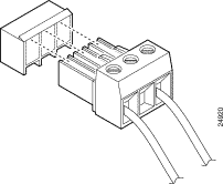
Step 2 Remove the terminal blocks from the receptacles on the rear of the power feed panel (see Figure 5).
To remove the cables from the power feed panel, complete the following steps:
 |
TimeSaver To make replacement easier, be sure that all cables are labeled. |

Step 2 Remove the cables (as many as four) from the N-type connectors on the rear of the power feed panel (see Figure 7).
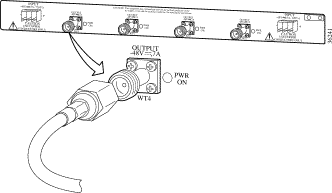
Step 3 Remove the screws from the ground lug (see Figure 8).

When removing the power feed panel from an equipment rack, refer to the following subsection, "Removing the Power Feed Panel from an Equipment Rack." When removing the power feed panel from a wall, refer to the "Removing the Power Feed Panel from a Wall" later in this section.
To remove the power feed panel from an equipment rack, complete the following steps:

Step 2 Lift the power feed panel out of the rack and place it on a work surface.
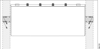
To remove the power feed panel from a wall or plywood backboard, remove the mounting screws
from both brackets while supporting the power feed panel (see Figure 10). After removing the mounting screws, move the power feed panel to a work surface.
Remove the brackets attached to each side of the power feed panel. Refer to Figure 11 when the unit is mounted with the front panel forward. Refer to Figure 12 when the unit is mounted with the rear panel forward. Refer to Figure 13 when the unit is mounted with the Telco center-mount brackets.


After you have removed the brackets, move the power feed panel to another location for shipment
or disposal.
To replace the multipoint headend power feed panel, complete the following procedures:
When installing the multipoint headend power feed panel in an equipment rack, refer to "Installing the Power Feed Panel in an Equipment Rack" in the following subsection. When installing the power feed panel on a wall or plywood backboard, refer to "Installing the Power Feed Panel on a Wall" later in this section.
To install the power feed panel in an equipment rack, complete the following steps:
Step 2 Attach the mounting brackets to both sides of the unit. Refer to Figure 14 when mounting the
power feed panel with the front panel forward. Refer to Figure 15 when mounting the power feed panel with the rear panel forward. Refer to Figure 16 when mounting the power feed panel in
a telco center-mount rack.


Step 3 Slide the unit into the rack.
Step 4 Attach the brackets on both sides of the power feed panel to the equipment rack (see Figure 17).

To install the power feed panel on a wall or plywood backboard, complete the following steps:
Step 2 Attach the wall-mounting brackets to both sides of the unit (see Figure 18).

 |
Note To allow the proper air flow through the unit when it is attached to a wall, the power feed panel must be installed with the rear panel connectors pointing up. |
Step 3 While supporting the power feed panel, attach the brackets on both sides of the unit to the wall or plywood backboard (see Figure 19).

To attach the cables to the new power feed panel, complete the following steps:

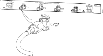
Step 2 Attach the cables (as many as four) to the N-type connectors on the rear of the power feed panel
(see Figure 21).
 |
Note Recommended torque for attaching the cables to the N-type ports is 35 to 40 inch-pounds. |
Step 3 Attach the cables (as many as four) to the SMA connectors on the front of the power feed panel
(see Figure 22).

 |
Note Recommended torque for attaching connectors to SMA ports is 7 to 9 inch-pounds. |
After replacing the power feed panel and attaching the cables, you must reinstate the power. To reinstate the power to the unit, complete the following steps:

Step 2 Plug the terminal blocks into the receptacles on the rear panel of the power feed panel (see Figure 24).

 |
Caution Never reinstate the power to the multipoint headend power feed panel before the terminal blocks are plugged in, or when any of the four power/breaker switches on the front of the unit are in the ON position. |
Step 3 Remove the tape from the circuit breaker switch handle, and reinstate power by moving the handle of the circuit breaker to the ON position.
Step 4 Switch to the ON position the power/breaker switches on the front of the unit that will be on active circuits (see Figure 23).
Using the procedures established at your installation, reinstate the wireless link with the no shut command.
This completes the procedure for removing and replacing the power feed panel in a Cisco broadband fixed wireless multipoint system headend.
This section provides international agency compliance, safety, and statutory information regarding the removal and replacement of the Cisco broadband fixed wireless multipoint system headend power feed panel.
The following paragraphs describe requirements and information based on FCC rules.
This Cisco product has been tested and complies with the limits for a Class A digital device, pursuant to Part 15 of the FCC Rules. These limits are designed to provide reasonable protection against harmful interference when the equipment is operated in a commercial environment. This equipment generates, uses, and can radiate radio-frequency energy and, if not installed and used in accordance with the instruction manual, can cause harmful interference to radio transmissions.
This section repeats in multiple languages the warnings found in this document.
| |||
Waarschuwing | Tijdens onweer dat gepaard gaat met bliksem, dient u niet aan het systeem te werken of kabels aan te sluiten of te ontkoppelen. | ||
Varoitus | Älä työskentele järjestelmän parissa äläkä yhdistä tai irrota kaapeleita ukkosilmalla. | ||
Attention | Ne pas travailler sur le système ni brancher ou débrancher les câbles pendant un orage. | ||
Warnung | Arbeiten Sie nicht am System und schließen Sie keine Kabel an bzw. trennen Sie keine ab, wenn es gewittert. | ||
Avvertenza | Non lavorare sul sistema o collegare oppure scollegare i cavi durante un temporale con fulmini. | ||
Advarsel | Utfør aldri arbeid på systemet, eller koble kabler til eller fra systemet når det tordner eller lyner. | ||
Aviso | Não trabalhe no sistema ou ligue e desligue cabos durante períodos de mau tempo (trovoada). | ||
¡Advertencia! | No operar el sistema ni conectar o desconectar cables durante el transcurso de descargas eléctricas en la atmósfera. | ||
Varning! | Vid åska skall du aldrig utföra arbete på systemet eller ansluta eller koppla loss kablar. | ||
| |||
Waarschuwing | Voordat u een van de onderstaande procedures uitvoert, dient u te controleren of de stroom naar het gelijkstroom circuit uitgeschakeld is. Om u ervan te verzekeren dat alle stroom UIT is geschakeld, kiest u op het schakelbord de stroomverbreker die het gelijkstroom circuit bedient, draait de stroomverbreker naar de UIT positie en plakt de schakelaarhendel van de stroomverbreker met plakband in de UIT positie vast. | ||
Varoitus | Varmista, että tasavirtapiirissä ei ole virtaa ennen seuraavien toimenpiteiden suorittamista. Varmistaaksesi, että virta on KATKAISTU täysin, paikanna tasavirrasta huolehtivassa kojetaulussa sijaitseva suojakytkin, käännä suojakytkin KATKAISTU-asentoon ja teippaa suojakytkimen varsi niin, että se pysyy KATKAISTU-asennossa. | ||
Attention | Avant de pratiquer l'une quelconque des procédures ci-dessous, vérifier que le circuit en courant continu n'est plus sous tension. Pour en être sûr, localiser le disjoncteur situé sur le panneau de service du circuit en courant continu, placer le disjoncteur en position fermée (OFF) et, à l'aide d'un ruban adhésif, bloquer la poignée du disjoncteur en position OFF. | ||
Warnung | Vor Ausführung der folgenden Vorgänge ist sicherzustellen, daß die Gleichstromschaltung keinen Strom erhält. Um sicherzustellen, daß sämtlicher Strom abgestellt ist, machen Sie auf der Schalttafel den Unterbrecher für die Gleichstromschaltung ausfindig, stellen Sie den Unterbrecher auf AUS, und kleben Sie den Schaltergriff des Unterbrechers mit Klebeband in der AUS-Stellung fest. | ||
Avvertenza | Prima di svolgere una qualsiasi delle procedure seguenti, verificare che il circuito CC non sia alimentato. Per verificare che tutta l'alimentazione sia scollegata (OFF), individuare l'interruttore automatico sul quadro strumenti che alimenta il circuito CC, mettere l'interruttore in posizione OFF e fissarlo con nastro adesivo in tale posizione. | ||
Advarsel | Før noen av disse prosedyrene utføres, kontroller at strømmen er frakoblet likestrømkretsen. Sørg for at all strøm er slått AV. Dette gjøres ved å lokalisere strømbryteren på brytertavlen som betjener likestrømkretsen, slå strømbryteren AV og teipe bryterhåndtaket på strømbryteren i AV-stilling. | ||
Aviso | Antes de executar um dos seguintes procedimentos, certifique-se que desligou a fonte de alimentação de energia do circuito de corrente contínua. Para se assegurar que toda a corrente foi DESLIGADA, localize o disjuntor no painel que serve o circuito de corrente contínua e coloque-o na posição OFF (Desligado), segurando nessa posição a manivela do interruptor do disjuntor com fita isoladora. | ||
¡Advertencia! | Antes de proceder con los siguientes pasos, comprobar que la alimentación del circuito de corriente continua (CC) esté cortada (OFF). Para asegurarse de que toda la alimentación esté cortada (OFF), localizar el interruptor automático en el panel que alimenta al circuito de corriente continua, cambiar el interruptor automático a la posición de Apagado (OFF), y sujetar con cinta la palanca del interruptor automático en posición de Apagado (OFF). | ||
Varning! | Innan du utför någon av följande procedurer måste du kontrollera att strömförsörjningen till likströmskretsen är bruten. Kontrollera att all strömförsörjning är BRUTEN genom att slå AV det överspänningsskydd som skyddar likströmskretsen och tejpa fast överspänningsskyddets omkopplare i FRÅN-läget. | ||
The following sections provide sources for obtaining documentation from Cisco Systems.
You can access the most current Cisco documentation on the World Wide Web at the following sites:
Cisco documentation and additional literature are available in a CD-ROM package, which ships with your product. The Documentation CD-ROM is updated monthly and may be more current than printed documentation. The CD-ROM package is available as a single unit or as an annual subscription.
Cisco documentation is available in the following ways:
If you are reading Cisco product documentation on the World Wide Web, you can submit technical comments electronically. Click Feedback in the toolbar and select Documentation. After you complete the form, click Submit to send it to Cisco.
You can e-mail your comments to bug-doc@cisco.com.
To submit your comments by mail, for your convenience many documents contain a response card behind the front cover. Otherwise, you can mail your comments to the following address:
Cisco Systems, Inc.
Document Resource Connection
170 West Tasman Drive
San Jose, CA 95134-9883
We appreciate your comments.
Cisco provides Cisco.com as a starting point for all technical assistance. Customers and partners can obtain documentation, troubleshooting tips, and sample configurations from online tools. For Cisco.com registered users, additional troubleshooting tools are available from the TAC website.
Cisco.com is the foundation of a suite of interactive, networked services that provides immediate, open access to Cisco information and resources at anytime, from anywhere in the world. This highly integrated Internet application is a powerful, easy-to-use tool for doing business with Cisco.
Cisco.com provides a broad range of features and services to help customers and partners streamline business processes and improve productivity. Through Cisco.com, you can find information about Cisco and our networking solutions, services, and programs. In addition, you can resolve technical issues with online technical support, download and test software packages, and order Cisco learning materials and merchandise. Valuable online skill assessment, training, and certification programs are also available.
Customers and partners can self-register on Cisco.com to obtain additional personalized information and services. Registered users can order products, check on the status of an order, access technical support, and view benefits specific to their relationships with Cisco.
To access Cisco.com, go to the following website:
The Cisco TAC website is available to all customers who need technical assistance with a Cisco product or technology that is under warranty or covered by a maintenance contract.
If you have a priority level 3 (P3) or priority level 4 (P4) problem, contact TAC by going to the TAC website:
P3 and P4 level problems are defined as follows:
In each of the above cases, use the Cisco TAC website to quickly find answers to your questions.
To register for Cisco.com, go to the following website:
http://www.cisco.com/register/
If you cannot resolve your technical issue by using the TAC online resources, Cisco.com registered users can open a case online by using the TAC Case Open tool at the following website:
http://www.cisco.com/tac/caseopen
If you have a priority level 1(P1) or priority level 2 (P2) problem, contact TAC by telephone and immediately open a case. To obtain a directory of toll-free numbers for your country, go to the following website:
http://www.cisco.com/warp/public/687/Directory/DirTAC.shtml
P1 and P2 level problems are defined as follows:

![]()
![]()
![]()
![]()
![]()
![]()
![]()
![]()
Posted: Fri Dec 15 10:13:16 PST 2000
Copyright 1989-2000©Cisco Systems Inc.