|
|

The minimum tasks required to make a Content Engine with Cache software operational in a network are as follows:
The procedures for these tasks are in the following sections:
For additional information on web caching concepts and network placement diagrams, refer to the Network Caching White Paper on the Cisco.com Content Networking website at the following URL:
http://www.cisco.com/warp/public/cc/pd/cxsr/500/tech/cds_wp.htm
To upgrade a Content Engine from earlier versions of the Cache software, use the new upgrade procedures in "Upgrading the System Software."
See "Cache Software Feature Configurations," for feature descriptions and sample configurations.
Cisco Cache software deployed on Content Engines is one of the content delivery elements of the Content Delivery Network (CDN) solution from Cisco Systems. The CDN solution from Cisco enables the proactive distribution of rich media files to Content Engines at the network edges for local access to e-business applications such as e-learning, e-commerce, knowledge sharing, and corporate communications. Designed for affordability and ease of installation, the CDN solution enables you to quickly deploy high-impact, high-bandwidth rich media, such as high-quality streaming video—with minimal administration.
Cisco Content Engines with Cache software accelerate content delivery by caching frequently accessed content (transparently or proxy-style) and then locally fulfilling content requests rather than traversing the Internet or intranet to a distant server farm. This solution helps to protect your network from uncontrollable bottlenecks and accelerates the delivery of content, enabling service providers to offer higher service quality and enabling enterprise employees to be more productive. By caching content such as Hypertext Transfer Protocol (HTTP) and File Transfer Protocol (FTP) traffic, Cisco Content Engines minimize redundant network traffic that traverses WAN links. As a result, WAN bandwidth costs either decrease or grow less quickly. This bandwidth optimization increases network capacity for additional users or traffic and for new services, such as voice.
Advanced Transparent Caching Service
Cisco Content Engines offer advanced caching transparency technologies that include:
To integrate with existing proxy infrastructures, the Cisco Cache software supports a number of proxied protocols, including FTP, Hypertext Transfer Protocol Secure (HTTPS), HTTP 1.0, HTTP 1.1, and Internet Communications Protocol (ICP). With the Rules Template feature, administrators can establish proxy policies, providing control over how traffic is proxied.
The Cisco Content Engines can be deployed in front of a website (reverse proxy) to transparently cache inbound requests for content, significantly reducing the traffic and TCP connection maintenance performed by origin servers.
By supporting the Web Cache Communication Protocol Version 2 (WCCPv2) or by interoperating with the Cisco CSS 1100 Series switches, a Content Engine can achieve a basic level of transparency that includes:
After you physically install the hardware, you must perform a basic software startup configuration by completing the tasks described in the following sections:
1. Gathering Network Information Required for Initializing the Cache Software
2. Procedure for Initializing the Cache Software
3. Logging On to the Graphical Management Interface (optional)
Have the following information available. When you power on the Content Engine for the first time, you will be prompted to provide this information:
To perform the basic startup configuration, complete the following steps:
After the Content Engine operating system boots up, the following prompt appears:
Would you like to enter the initial configuration? [yes]:
Step 2 Enter yes, and then enter values for the following fields as you are prompted:
After you enter the initial configuration data, the following prompt appears:
Use this configuration? [yes]:
Step 3 If the initial configuration is acceptable, enter yes or press Enter.
The Content Engine performs hardware and software initialization tasks and then serves a login challenge that, when answered correctly, launches the CLI. At this point, the initial configuration is complete.
Administrator entries are shown in bold.
Would you like to enter the initial configuration? [yes]:yes

host name: 590-1

domain name: bubu.net

admin password: diamond

Please enter an interface from the following list:
   0: FastEthernet 0/0
   1: FastEthernet 0/1
enter choice: 0

cache IP address: 172.10.13.8

IP network mask: 255.255.255.0

gateway IP address: 172.10.13.7

DNS server: 172.10.2.200

Use this configuration? [yes]: yes

INIT: Entering runlevel: 3
Entering non-interactive startup
Starting cron daemon: [  OK  ]

Cisco Content Engine Console

Username: Partition disk00/00 identified as SWFS
disk00/00 has been checked OK
Partition disk00/01 identified as SYSFS
disk00/01 has been checked OK
Partition disk01/01 identified as MEDIAFS
disk01/01 has minor problem, but fixed. Return code = 1
Partition disk02/00 identified as CFS
Partition disk03/00 identified as CFS
Partition disk04/00 identified as CFS
Partition disk06/00 identified as MEDIAFS
disk06/00 has minor problem, but fixed. Return code = 1
Partition disk07/00 identified as CFS
disk00  (scsi host 0, channel 0, id 0)
disk01  (scsi host 0, channel 0, id 1)
disk02  (scsi host 0, channel 0, id 8)
disk03  (scsi host 0, channel 0, id 9)
disk04  (scsi host 0, channel 0, id 10)
disk05  (scsi host 0, channel 0, id 11)
disk06  (scsi host 0, channel 0, id 12)
disk07  (scsi host 0, channel 0, id 13)
Mounting disk00/00 as SWFS ...succeeded
Mounting disk00/01 as SYSFS ...succeeded
Mounting disk01/01 as MEDIAFS ...succeeded
Mounting disk06/00 as MEDIAFS ...succeeded
Disk configuration is initialized

Cisco Content Engine Console

Username:admin

Password:diamond


System Initialization Finished.


590-1 con now available


Press RETURN to get started!
Upon completion of the above procedure, you are ready to perform basic and advanced Cache software network configurations.
You can configure the Cache software with the CLI or with the Cache software graphical management interface. This guide contains only CLI configuration examples. The graphical management interface has separate online help for those Cache software features supported with the graphical management interface.
To connect to the graphical management interface, perform the following steps.
 |
Note Be sure to enable Java, JavaScript, and style sheets on your web browser. |
Step 2 Open the URL with the cache IP address specified in the initial Cache software configuration. Append the default port number 8001. For example:
http://172.10.13.8:8001
You are prompted for a username and password. (See Figure 1-1.)
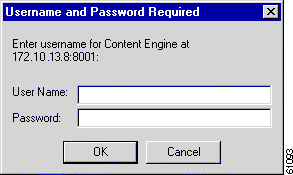
Step 3 Enter a correct username and password. The Content Engine returns the graphical management interface home page, as shown in Figure 1-2.
If you forget your password, you must have another administrator reset your password. The password for the user admin is specified in the initial system configuration dialog.
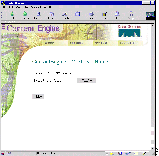
 |
Note Cisco Cache software, Release 3.1.0 and 3.1.1, do not implement the System menu on the graphical management interface. |
Router or switch configuration is required for transparent caching and reverse proxy caching services. The router or switch must be running a version of IOS that supports the Web Cache Communication Protocol (WCCP) Version 2. Configuration scenarios for WCCP Version 1 are not included in this guide, but are discussed in "Web Cache Communication Protocol Version 1."
When cache support is enabled on the router or switch, and WCCP support is enabled on the Content Engines, the devices can communicate and deliver the services for which they are configured. To suspend proxy and caching services, you can disable cache support on the router or switch rather than powering off or otherwise disabling individual Content Engines. (For instance, use the no ip wccp router or switch command to disable caching.)
 |
Note Cache software 3.1 initializes with WCCP Version 2 as the default. |
Many WCCP Version 2 features also require a configuration of the Cache software wccp global configuration command. Refer to the Cache software command reference and release notes for more details.
If you do not know how to configure a router or a switch, refer to the software documentation supplied with the devices. Further information on WCCP Version 2 commands and router configuration examples are in the Cisco IOS online documentation as well as in "Web Cache Communication Protocol Version 2."
For WCCP and Cisco Express Forwarding (CEF) to work properly together, CEF must be enabled before WCCP is enabled in the router configuration sequence, as shown in Example 1-1. If CEF is enabled after WCCP, performance is markedly degraded.
router(config)# ip cef

. . .
router(config)# ip wccp web-cache

router(config)# interface Ethernet0

router(config-if)# ip route-cache same-interface

router(config-if)# exit

router(config)# interface Serial0

router(config-if)# ip web-cache redirect out

router(config-if)# exit
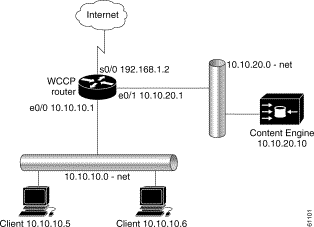
In this scenario, the Content Engine and the requesting clients are on different subnets. The topology is depicted in Figure 1-3.
A router running WCCP Version 2 transparently redirects client HTTP traffic bound for router interface s0/0 to the Content Engine. The web cache service redirects HTTP traffic on port 80 only.
To configure the Content Engine for the web cache service, perform the following steps while logged into the Cache software global configuration mode:
Command | Purpose | |
Step 1 | contentengine(config)# wccp version 2
| Ensures that the Content Engine is running WCCP Version 2. |
Step 2 | contentengine(config)# wccp router-list 1 10.10.20.1
| Configures a router list. |
Step 3 | contentengine(config)# wccp web-cache
router-list-num 1
| Informs the routers in the specified router list that the Content Engine is accepting web cache service. |
Step 4 | contentengine(config)# exit
| Exits global configuration mode. |
Step 5 | contentengine# write memory
| Writes running configurations to nonvolatile memory. |
Step 6 | Building configuration... [OK]
| This message appears after a successful write command is issued. |
To configure the router for web cache service, perform the following steps while logged into the router global configuration mode:
| Command | Purpose |
Step 1 | router(config)# ip wccp web-cache
| Instructs the router to run the web cache service. |
Step 2 | router(config)# interface Serial0
| Specifies which router interface to configure. In this scenario, Serial0 is the router interface to the Internet. |
Step 3 | router(config-if)# ip wccp web-cache redirect out
| Instructs the router to redirect web-cache traffic bound for the specified interface to Content Engines that accept web cache service. In this scenario there is only one. Web cache traffic is defined as HTTP packets on port 80. |
Step 4 | router(config-if)# exit
| Exits global configuration mode. |
This example shows a Content Engine and router configured for the web cache service with the topology illustrated in Figure 1-3:
Content Engine Configuration
. . .
hostname Cache_engine_3.1
!
clock timezone pst -8 0
!
ip domain-name cnbu.net
!
exec-timeout 20
!
interface FastEthernet 0
ip address 10.10.20.10 255.255.255.0
no autosense
bandwidth 100
full-duplex
exit
interface FastEthernet 1
shutdown
exit
!
ip default-gateway 10.10.20.1
!
ip name-server 10.10.10.100
!
icp client enable
!
wccp router-list 1 10.10.20.1

wccp web-cache router-list-num 1

!
!
error-handling send-cache-error
!
. . .
WCCP-Enabled Router Configuration
Building configuration...

Current configuration:
!
hostname WCCP-Router
!
!
ip subnet-zero
!
ip wccp web-cache
!
interface Ethernet0
 ip address 10.10.10.1 255.255.255.0
!
interface Ethernet1
 ip address 10.10.20.1 255.255.255.0
!
interface Serial0
 ip address 192.168.1.2 255.255.255.252
 no ip directed-broadcast
 no ip mroute-cache
 ip wccp web-cache redirect out
 !
end
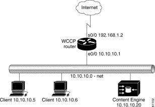
In this scenario, the Content Engine and the requesting clients are on the same subnet. The topology is depicted in Figure 1-4.
A router running WCCP Version 2 transparently redirects client HTTP traffic bound for router interface s0/0 to the Content Engine. The web cache service redirects HTTP traffic on port 80 only.
To configure the Content Engine for the web cache service, perform the following steps while logged into the Cache software global configuration mode:
| Command | Purpose | |
|---|---|---|
Step 1 | contentengine(config)# wccp version 2
| Ensures that Content Engine is running WCCP Version 2. |
Step 2 | contentengine(config)# wccp router-list 1 10.10.10.1
| Configures a router list. |
Step 3 | contentengine(config)# wccp web-cache
router-list-num 1
| Informs the routers in the specified router list that the Content Engine is accepting web cache service. |
Step 4 | contentengine(config)# exit
| Exits global configuration mode. |
Step 5 | contentengine# write memory
| Writes running configurations to nonvolatile memory. |
Step 6 | Building configuration... [OK]
| This message appears after a successful write command is issued. |
To configure the router for the web cache service, perform the following steps while logged into the Cache software global configuration mode:
| Command | Purpose | |
|---|---|---|
Step 1 | router(config)# ip wccp web-cache
| Instructs the router to run the web cache service. |
Step 2 | router(config)# interface Ethernet0
| Specifies which router interface to configure. In this scenario, Ethernet0 is the router interface to which the Content Engine and clients are connected. |
Step 3 | router(config-if)# ip route-cache same-interface
| Enables fast switching of redirected packets back through the interface on which they were received. Without this command, the router does not use the high-speed switching cache, and the packets are process-switched, a much slower method. |
Step 4 | router(config)# interface Serial0
| Specifies which router interface to configure. In this scenario, Serial0 is the router interface to the Internet. |
Step 5 | router(config-if)# ip wccp web-cache redirect out
| Instructs the router to redirect web cache traffic bound for the specified interface to Content Engines that accept web cache service. In this scenario there is only one. Web cache traffic is defined as TCP port 80 traffic. |
Step 6 | router(config-if)# exit
| Exits global configuration mode. |
This example shows a Content Engine and router configured for the web cache service with the topology illustrated in Figure 1-4:
Content Engine
hostname Cache_engine_3.1
!
clock timezone pst -8 0
!
ip domain-name cu.net
!
interface FastEthernet 0
ip address 10.10.20.10 255.255.255.0
no autosense
bandwidth 100
full-duplex
exit
interface FastEthernet 1
shutdown
exit
!
ip default-gateway 10.10.20.1
!
ip name-server 10.10.10.100
!
icp client enable
!
!
wccp router-list 1 10.10.20.1

wccp web-cache router-list-num 1

wccp slow-start enable

!
!
error-handling send-cache-error
!
. . .
WCCP-Enabled Router
Building configuration...

Current configuration:
!
version 12.0
!
hostname WCCP-Router
!
!
ip wccp web-cache
!
interface Ethernet0
 ip address 10.10.10.1 255.255.255.0
 ip route-cache same-interface

!
interface Serial0
ip address 192.168.1.2 255.255.255.252
no ip directed-broadcast
no ip mroute-cache
ip wccp web-cache redirect out

 !
end
To ensure fast response times, maximized service availability and the ability to withstand flash-crowds, the Cisco Content Engines with Cache software can be deployed in front of a website server farm to offload traffic from busy firewalls and servers, helping to optimize the entire website infrastructure. This type of deployment is called web server acceleration, or reverse proxying.
The same Content Engine can be providing a reverse proxy cache service while simultaneously providing a transparent network cache service.
In the deployment scenario shown in Figure 1-5, the Content Engine interoperates with a router running WCCP Version 2 to bring the reverse proxy service within the web server environment. In this deployment, the router interface connected to the Internet has an IP address of 192.168.1.1. All HTTP requests destined for the web server are routed to the router interface of 172.16.21.1. Upon receiving the HTTP request at this interface, the router transparently intercepts and redirects the request to the Content Engine with an IP address of 172.16.20.23. Thus, the Content Engine is logically in front of the web server offloading web server HTTP traffic. The Content Engine sends a request to the web server only when it does not find the requested content in the cache.
 |
Note A redirect list on the router or a static bypass list on the Content Engine can be used to allow flows to bypass interception. These lists use criteria based on source and destination IP addresses. |
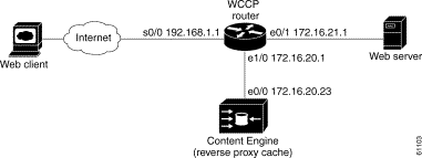
To configure reverse proxy on the Content Engine, perform the following steps starting from global
configuration mode:
| Command | Purpose | |
|---|---|---|
Step 1 | contentengine(config)# wccp version 2
| Ensures that the Content Engine is running WCCP Version 2. |
Step 2 | contentengine(config)# wccp router-list 1
172.16.20.1
| Configures a router list. |
Step 3 | contentengine(config )# wccp 99 reverse-proxy
router-list-num 1
| Instructs the router to run the reverse proxy service (service 99). |
To configure reverse proxy service on the router, perform the following steps starting from global configuration mode:
| Command | Purpose | |
|---|---|---|
Step 1 | router(config)# ip wccp 99
| Instructs the router to run the reverse proxy service. |
Step 2 | router(config)# interface Ethernet 0/1
| Specifies which router interface to configure. In this scenario, Ethernet 0/1 is the router interface to the web server. |
Step 3 | router(config-if)# ip wccp 99 redirect out
| Instructs the router to redirect TCP port 80 traffic bound for the specified interface to Content Engines that accept reverse proxy service. In this scenario there is only one. |
Step 4 | router(config)# exit
| Exits global configuration mode. |
| Command | Purpose | |
|---|---|---|
Step 1 | router(config)# ip wccp 99
| Instructs the router to run the reverse proxy service. |
Step 2 | router(config)# interface s0/0
| Specifies which router interface to configure. In this scenario, s0/0 is the router interface to the Internet. |
Step 3 | router(config-if)# ip wccp 99 redirect in
| Instructs the router to redirect TCP port 80 traffic received on the specified interface to Content Engines that accept reverse proxy service. |
Step 4 | router(config-if)# exit
| Exits interface configuration mode. |
 |
Note Input redirection is supported in Cisco IOS Release 12.1(3)T or 12.0(11)S and later versions of the same, or in Cisco IOS Release 12.2. |
This section shows configurations of the Content Engine and the router for the deployment scenario in Figure 1-5. The reverse proxy related commands are in bold:
Content Engine
 !
 hostname ContentEngine
 !
 interface ethernet 0
  ip address 172.16.20.23 255.255.255.224
  ip broadcast-address 10.0.0.255
 exit
 !
 interface ethernet 1
 exit
 !
 ip default-gateway 172.16.20.226
 ip name-server 172.16.20.238
 ip domain-name cisco.com
 ip route 0.0.0.0 0.0.0.0 172.16.20.238
 !
 wccp router-list 1 172.16.20.1

 wccp 99 reverse-proxy router-list-num 1

 wccp version 2

 !
 end
WCCP-Enabled Router
Current configuration:
 !
 version 12.1
 service timestamps debug uptime
 service timestamps log uptime
 no service password-encryption
 !
 hostname 2611-5
 !
 enable secret 5 $1$9VQ.$BTPbq8xlE2dsKwKPDDmpL/
 !
 !
 ip subnet-zero
 ip wccp 99

 !
 !
 interface Ethernet0/0
  no ip address
  no ip redirects
  !
 interface Serial0/0
  ip address 192.168.1.1 255.255.255.224
  !
 interface Ethernet0/1
  ip address 172.16.21.1 255.255.255.224
  ip wccp 99 redirect out

!
 interface Ethernet1/0
  ip address 172.16.20.1 255.255.255.224
  !
 interface Ethernet1/1
  no ip address
  shutdown
  full-duplex
 !
 interface Ethernet1/2
  no ip address
  shutdown
 !
. . .
 ip classless
 !
 !
 line con 0
  transport input none
 line aux 0
 line vty 0 4
  login
 !
 end
To remove a Content Engine from a Content Engine cluster or from a WCCP environment without powering it down, disable the running version of WCCP on the Content Engine by issuing the Cache software no wccp version 1 (or 2) global configuration command. The Content Engine will still service proxy-style requests, if so configured, and preserve its configuration settings.
Further information about the Content Engine commands used to configure the Content Engine for the deployment scenarios provided in this chapter can be found in the Cisco Cache Software Command Reference, Release 3.1. Refer to this document for more information about the Content Engine commands.
Once you have installed and configured the Content Engine and enabled WCCP caching services on the router, verify that the Cache software is working properly.
Step 2 From the CLI, enter the following command to display the Content Engine HTTP caching saving statistics:
show statistics http savings
Step 3 Open a console or Telnet session on the home router or routers, and enter the show ip wccp commands to display statistics and status information about the Content Engine.
The statistics should show a number greater than 0 for packets redirected. Also, check for hash assignments, which indicate at the very least that the Content Engines are registered and communicating with the routers.
If the router shows that no packets are being redirected to the Content Engine, you must troubleshoot your setup.
Refer to the Content Engine hardware documentation for instructions on physically removing a Content Engine from an active network.
The router and the Content Engine are in constant communication; thus, when the router notices that the engine is no longer responding to it, the router stops sending requests to the engine. This is transparent to users. If other Content Engines are attached to the router, the router continues sending requests to the other engines.
When you remove a Content Engine, the pages that were cached on its hard disks are no longer available to the router or other Content Engines. Thus, you might see an increase in outgoing web traffic that might have otherwise been fulfilled by the Content Engine you are removing. However, after a time, the router and other Content Engines will redistribute the load of web traffic.
If you remove the last Content Engine from a router, you can also disable cache support on the router. However, this is not necessary; having cache support enabled when there are no Content Engines attached has no effect on the router's performance.
To replace a Content Engine, remove the old one from the network. Then, add the new Content Engine and configure it using the same startup configuration parameters that you used for the removed one.
![]()
![]()
![]()
![]()
![]()
![]()
![]()
![]()
Posted: Tue Jun 19 17:06:19 PDT 2001
All contents are Copyright © 1992--2001 Cisco Systems, Inc. All rights reserved.
Important Notices and Privacy Statement.