|
|

After you determine where you want to put the Cache Engine, complete the following tasks to install the Cache Engine:
1. Collecting the Information Required for Configuration
2. Installing the Cache Engine
3. Initializing the Cache Engine Configuration
4. Enabling Cache Support on the Router
Read the Regulatory Compliance and Safety Information for Cisco
Cache Engine 500 Series document that came with the Cache Engine before you begin the installation.
This chapter also covers the following tasks:
 |
Warning Read the installation instructions before you connect the system to its power source. |
Before you install the Cache Engine, collect the following information required for the basic configuration:
When you power up the Cache Engine for the first time, you will be prompted to provide the information listed above.
 |
Warning Before working on a system that has an on/off switch, turn OFF the power and unplug the power cord. |
 |
Warning The device is designed to work with TN power systems. |
 |
Warning This unit is intended for installation in restricted access areas. A restricted access area is where access can only be gained by service personnel through the use of a special tool, lock and key, or other means of security, and is controlled by the authority responsible for the location. |
 |
Warning To avoid electric shock, do not connect safety extra-low voltage (SELV) circuits to telephone-network voltage (TNV) circuits. LAN ports contain SELV circuits, and WAN ports contain TNV circuits. Some LAN and WAN ports both use RJ-45 connectors. Use caution when connecting cables. |
 |
Warning This product relies on the building's installation for short-circuit (overcurrent) protection. Ensure that a fuse or circuit breaker no larger than 120 VAC, 15A U.S. (240 VAC, 10A international) is used on the phase conductors (all current-carrying conductors). |
 |
Warning This equipment is intended to be grounded. Ensure that the host is connected to earth ground during normal use. |
 |
Warning Do not work on the system or connect or disconnect cables during periods of lightning activity. |
 |
Warning Before working on equipment that is connected to power lines, remove jewelry (including rings, necklaces, and watches). Metal objects will heat up when connected to power and ground and can cause serious burns or weld the metal object to the terminals. |
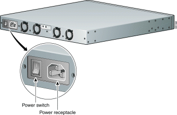
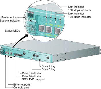
Refer to Figure 2-1 and Figure 2-2 when installing the Cache Engine, to help you identify the connectors on the front and rear of the Cache Engine.
 |
Caution Make sure to tighten the jackscrews on the SCSI cable. |
Boot sequence:
* * * *1 Steady Power on, first-, and second-level bootstrap * o o o2 Steady Image loaded and running - - - - 3 Rolling Network hardware initialization o * o o Steady Network hardware initialization complete - - - - Rolling Disk hardware initialization * * o o Steady Disk hardware initialization complete o o * o Steady First IP packet received o o o o Steady First HTTP cache request received
0 1 2 3 LEDs
Appearance
Meaning
1* = LED is on.
2o = LED is off.
3- - - = rolling display.
When the Cache Engine is up and running:
o o o o1 Steady Normal operation o * * *2 Steady An exception has occurred (software or hardware failure) * * * * Steady A panic has occurred (software failure) - - - - 3 Rolling Reboot has begun
0 1 2 3 LEDs
Appearance
Meaning
1o = LED is off.
2* = LED is on.
3- - - = rolling display.
Figure 2-1: Cache Engine, Rear View


To install the Cache Engine, perform the following steps:
Step 2 Connect the power cord to the power cord receptacle of the Cache Engine and to an AC (alternating current) power source.
Step 3 Connect the network cable into the Ethernet port on the Cache Engine.
Step 4 Connect the console serial cable into the console port on the Cache Engine.
Use the Cisco-supplied serial cable. Open a window for the Cache Engine console using your terminal emulation program.
Step 5 Power on the Cache Engine.
The Cache Engine begins booting and sends messages to the console window. Once the operating system boots, you are ready to initialize the basic software configuration.
To initialize the Cache Engine's basic configuration once it has booted the operating system, perform the following steps:
 |
Note The Cache Engine does not display ***** (asterisks) while you are verifying your admin password. |
---- System Configuration Dialog ----
You may use Ctrl-D to abort Configuration Dialog at any prompt.
Would you like to enter the initial configuration? [yes]: yes

host name: cache

domain name: cisco.com

admin password: test

cache IP address: 10.1.58.5

IP network mask: 255.255.255.0
gateway IP address: 10.1.58.1

DNS server: 172.16.2.132
Step 2 If the basic configuration is acceptable, enter yes. The Cache Engine indicates whether the configuration is accepted. At this point, the basic configuration is finished.
Use this configuration? [yes]: yes

>> Building configuration...
>> . . START - phase complete
Once you have entered an acceptable basic configuration, the Cache Engine displays the URL that you would use to connect to it with a web browser, for example, http://10.1.1.1:8001. You must use the complete URL to connect to the Cache Engine and manage it.
The username is admin and the password is supplied by the user in the
Login window.
Before the router can use the Cache Engine, it must know that the Cache Engine exists. This notification is done automatically by communications between the engine and the router. However, you must enable cache support in the router so that the router listens for the Cache Engine.
If you later want to disable caching temporarily, you can do so by disabling cache support in the router, rather than by turning off or otherwise disabling the individual Cache Engines. (Use the no ip wccp command on the router to disable caching.)
You must already know how to configure the router to make these configuration changes. If you do not know how to configure the router, consult the Cisco IOS documentation supplied with the router. Detailed information for the commands mentioned here is in the Cisco IOS documentation. See "Web Cache Communication Protocol Version 1," and "Web Cache Communication Protocol Version 2," for information on which IOS software supports which version of WCCP on which platform.
ip wccp enable
For example, to enable redirection, enter:
ip web-cache redirect
You can confirm your settings using the following show commands on the router:
In global configuration mode, use the ip wccp command to enable cache support. For example, enter:
ip wccp webcache
or
ip wccp service-number
where service-number is the number of predefined services (0 to 99)
For example, to enable redirection on port 80, enter:
router(config-if): ip web-cache redirect out
To enable redirection of HTTP traffic on port 80 and on another port, enter:
router(config-if): ip wccp 98 redirect out
You can confirm your settings using the following show commands on the router:
Once you have installed and configured the Cache Engine and enabled caching on the router, check to ensure that the Cache Engine is working properly.
Step 2 From the command-line interface (CLI), enter the following to display the Cache Engine HTTP caching saving statistics:
show statistics http savings
Step 3 Open a window for the Cache Engine console using your terminal emulation program to connect to the home router or routers, and enter the show ip wccp web-cache command to display information about the Cache Engine. The entry for the Cache Engine should show a number greater than 0 for packets redirected. Also, check for hash assignments.
If the router shows that no packets are being redirected to the Cache Engine, you must troubleshoot your setup.
You can manage the Cache Engine using the CLI or the Cache Engine management interface. To connect to the Cache Engine's management interface:
 |
Note Be sure to enable Java, JavaScript, and Cascading Style Sheets on your Internet Explorer or Netscape 4.0 or later browser. |
Step 2 Open the URL for the Cache Engine, to the URL used in the basic configuration, for example, http://10.1.1.1:8001.
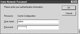
You must include the port number, such as 8001, in the URL.You are prompted for a username and password. (See Figure 2-3.)

Step 3 Enter a correct username and password. The Cache Engine returns the initial management page, which contains links to other management pages.
If you forget your password, you must have another administrator reset your password.
 |
Warning Before working on a system that has an On/Off switch, turn OFF the power and unplug the power cord. |
 |
Warning Ultimate disposal of this product should be handled according to all national laws and regulations. |
To remove a Cache Engine from a system, turn off the engine's power and physically remove it from the network.
The router and the Cache Engine are in constant communication; thus, when the router notices that the engine is no longer responding to it, the router stops sending requests to the engine. This is transparent to users. If other Cache Engines are attached to the router, the router continues sending requests to the
other engines.
When you remove a Cache Engine, the pages that were cached on the engine are no longer available to the router or other Cache Engines. Thus, you might see an increase in outgoing web traffic that might have otherwise been fulfilled by the engine you are removing. However, after a time, the router and other Cache Engines will have redistributed the load of web traffic.
If you remove the last Cache Engine from a router, you can also disable cache support on the router. However, this is not necessary; having cache support enabled when there are no Cache Engines attached has no effect on the router's performance.
To replace a Cache Engine, remove the old engine from the network. Then, add the new engine and configure it using the same configuration parameters (IP address, and so forth) that you used for the removed engine.
The Cache Engine comes with a console cable kit that includes the following cable and adapters:
Use this cable to connect the Cache Engine console port to the COM port of an ASCII terminal or a PC running terminal emulation software.
An Ethernet cable is required to connect the Cache Engine to your network.
This section has pinout information for common cable configurations to assist you in purchasing or building replacement cables.
To connect the Cache Engine to your network, you must use one of the following cables:
 |
Note The Ethernet ports on the Cache Engine are MDI. |
Use a Category 5 or better UTP cable to connect to a 100BaseT network. Use a Category 3 or better UTP cable to connect to a 10BaseT network.
Table 2-1 shows the pinouts for a straight-through 100BaseT cable.
Table 2-2 shows the pinouts for a crossover 100BaseT cable.
| RJ-45 Pin | Signal | RJ-45 Pin |
|---|---|---|
1 | TX+ | 1 |
2 | TX- | 2 |
3 | RX+ | 3 |
4 | — | 4 |
5 | — | 5 |
6 | RX- | 6 |
7 |
| 7 |
8 |
| 8 |
| RJ-45 Pin | Signal | RJ-45 Pin |
|---|---|---|
1 | TX+ | 3 |
2 | TX- | 6 |
3 | RX+ | 1 |
4 |
| 4 |
5 |
| 5 |
6 | RX- | 2 |
7 |
| 7 |
8 |
| 8 |
The console port on the Cache Engine is configured as data terminal equipment (DTE) and uses an RJ-45 connector. A console cable kit is provided with your Cache Engine to connect a console (an ASCII terminal or PC running terminal emulation software) to the console port. The console cable kit contains an RJ-45 to RJ-45 rollover cable and two RJ-45 to DB-9 female DTE adapters.
By attaching an RJ-45 to DB-9 adapter to the rollover cable, you create an RJ-45 to DB-9 null modem cable.
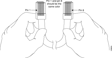
You can identify a rollover cable by comparing the two modular ends of the cable, as shown in Figure 2-4. Holding the cable ends in your hands, side by side, with the tab at the back, the wire connected to the pin on the outside of the left connector (pin 1) should be the same color as the pin on the outside of the right connector (pin 8).

![]()
![]()
![]()
![]()
![]()
![]()
![]()
![]()
Posted: Tue Jun 5 19:05:42 PDT 2001
All contents are Copyright © 1992--2001 Cisco Systems, Inc. All rights reserved.
Important Notices and Privacy Statement.