|
|

This chapter describes the Cisco Content Router 4400, its specifications, and considerations for using the system. Take time to plan the placement of the Content Router on your network for maximum benefit.
This chapter contains the following sections:
Content routing routes clients to the replicated-content site (typically a mirror site) that can serve them most quickly and efficiently. The Content Router 4400 redirects a client to the "closest" (best) replicated-content site, based on network delay using a software process called boomerang. The
Content Router 4400 load balances from 2 to 20 sites for each domain it is configured to support.
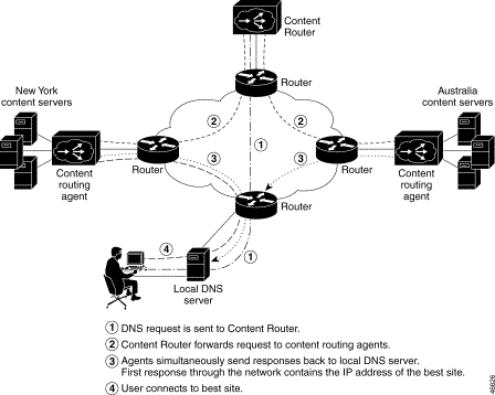
In direct mode, the Content Router is configured as the authoritative DNS server for the fully qualified domain name being routed. For example, to route www.foo.com, the address (A) record in the primary DNS server for www.foo.com is changed to a name server (NS) record pointing to the Content Router. All requests for the IP address of www.foo.com are handled by the Content Router and its agents. When a request comes through, the agents respond at exactly the same time. The first response through the network wins the race, and is therefore the site to which the client connects. Figure 1-1 provides an overview of the boomerang process in direct mode.
In WCCP mode, the Content Router works in conjunction with the access routers at the edge of the network to allow an Access Service Provider or enterprise to make DNS-based routing decisions based on the actual client request, rather than on the client DNS server. The DNS requests are intercepted by WCCP running on the access routers at the edge, and all requests are funneled to the Content Router. Any request that does not come from one of the Content Router's configured domains is passed on to the DNS server in the original request. If the request is from one of the Content Router's configured domains, the Content Router initiates the DNS race. The DNS race occurs in the same manner as described above: all agents send a response at the same moment, and the first response through the network is the site to which the client connects. Figure 1-2 provides an overview of the boomerang process in WCCP mode.
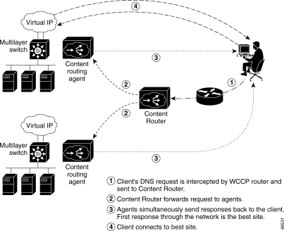
Figure 1-3 provides a closer look at the first part of the boomerang process, in which the Content Router determines the one-way delay it uses when sending requests to the agents. This one-way delay ensures that the agents will begin the DNS race simultaneously.
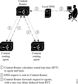
Table 1-1 lists the storage and memory specifications for the Content Router 4400.
| Item | Description |
|---|---|
Internal hard disk storage | 2 9.1-GB Ultra2 LVD SCSI hard drives |
Expandable storage | 108 GB maximum |
Memory | 8-MB Flash memory 256-MB SDRAM |
Figure 1-4 shows the Content Router front panel. Figure 1-5 shows the Content Router rear panel.
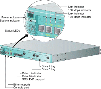
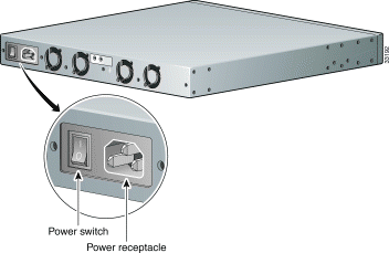
Table 1-2 describes the front and back panel ports and receptacles. (See the front panel in Figure 1-4 and the rear panel in Figure 1-5.)
| Item | Description |
|---|---|
| Front Panel | |
This serial port connects to a console. | |
The Ethernet 0 cable connects to this port. | |
Not currently supported. | |
Not currently supported. | |
Bay for hard drive 0. | |
Drive 1 | Bay for hard drive 1. |
| Back Panel | |
The AC power cord connects to this plug. | |
This switch toggles between on and off, even though the switch always returns to its initial position after you press it. A power light on the front panel, when lit, indicates that the power is on. | |
 |
Warning To avoid electric shock, do not connect safety extra-low voltage (SELV) circuits to telephone-network voltage (TNV) circuits. LAN ports contain SELV circuits, and WAN ports contain TNV circuits. Some LAN and WAN ports both use RJ-45 connectors. Use caution when connecting cables. |
Table 1-3 describes the LEDs on the front panel.
| Indicator | Color | State | Description |
|---|---|---|---|
Green | On | Power is flowing to the Content Router. | |
Green | On | The network connection is active (packets are being sent or received). | |
Green | On | The Content Router is connected to the network. | |
Green | On | The connection is a 100BASE-TX (Fast Ethernet) connection. | |
Green | On | Drive 0 is active. | |
Green | On | Drive 1 is active. | |
Green | Steady | In a steady display, the state of each LED is constant. (See Table 3-1 for the meanings of steady state LED variations.) | |
Rolling | Reboot has begun. In a rolling display, the four LEDs give the appearance of a light that repeatedly moves from left to right. |
This section describes the cables and connectors that connect your Content Router to a terminal and to the external network.
The Content Router comes with a console cable kit that includes the following cable and adapters:
Use the rollover cable to connect the Content Router console port to the COM port of an ASCII terminal or a PC running terminal emulation software.
The console port on the Content Router is configured as data terminal equipment (DTE) and uses an RJ-45 connector. A console cable kit is provided with your Content Router to connect a console (an ASCII terminal or PC running terminal emulation software) to the console port. The console cable kit contains an RJ-45 to RJ-45 rollover cable and two RJ-45 to DB-9 female DTE adapters.
By attaching an RJ-45 to DB-9 adapter to the rollover cable, you create an RJ-45 to DB-9 null modem cable.
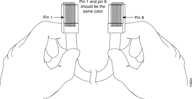
You can identify a rollover cable by comparing the two modular ends of the cable, as shown in Figure 1-6. Holding the cable ends in your hands, side by side, with the tab at the back, the wire connected to the pin on the outside of the left connector (pin 1) should be the same color as the pin on the outside of the right connector (pin 8).
An Ethernet cable is required to connect the Content Router to your network. To connect the Content Router to your network, you must use one of the following types of cables:
 |
Note The Ethernet ports on the Content Router are MDI. |
Use a Category 5 UTP cable to connect to a 100BASE-T network.
The following pinout information for common cable configurations can assist you in purchasing or building replacement cables.
Table 1-4 shows the pinout for a straight-through 100BASE-T cable.
| RJ-45 Pin | Signal | RJ-45 Pin |
|---|---|---|
1 | TX+ | 1 |
2 | TX- | 2 |
3 | RX+ | 3 |
4 | — | 4 |
5 | — | 5 |
6 | RX- | 6 |
7 | — | 7 |
8 | — | 8 |
Table 1-5 shows the pinout for a crossover 100BASE-T cable.
| RJ-45 Pin | Signal | RJ-45 Pin |
|---|---|---|
1 | TX+ | 3 |
2 | TX- | 6 |
3 | RX+ | 1 |
4 | — | 4 |
5 | — | 5 |
6 | RX- | 2 |
7 | — | 7 |
8 | — | 8 |
Table 1-6 lists hardware specifications for the Cisco Content Router 4400 hardware.
| Specification | Description |
|---|---|
366-MHz | |
Intel 82588 | |
Ultra2 SCSI LVD | |
Height: 1.72 in. (4.37 cm) Width: 17.5 in. (44.45 cm) Depth: 14.1 in. (35.8 cm) | |
12.5 lb (5.7 kg) | |
| |
Console: 1 RJ-45 connector Network: 2 10/100BASE-TX Ethernet RJ-45 connectors (MDI) External SCSI: 68-pin high-density connector (Ultra2 LVD) | |
80 Mbps | |
Maximum station-to-station cabling distances | 10/100BASE-TX Ethernet, Category 5 UTP: 328 ft (100 m) SCSI Ultra2 LVD: 39 ft (12 m) |
Refer to the Regulatory Compliance and Safety Information document, which was supplied with your Content Router. | |
Rack-mounted, middle, front, or back (standard 19-in. [48.26-cm] and 23-in. [58.42-cm] racks) | |
Operating: 41 to 104°F (5 to 40°C) Nonoperating: -13 to 158°F (-25 to 70°C) | |
5 to 95%, noncondensing |
![]()
![]()
![]()
![]()
![]()
![]()
![]()
![]()
Posted: Fri Dec 29 10:31:03 PST 2000
Copyright 1989-2000©Cisco Systems Inc.