|
|

Table Of Contents
VISM and PXM Display, Log, and Diagnostic Loopback Path CLI Commands
PXM Diagnostic Loopback Path CLI Commands
PXM1E and PXM 45 Display CLI Commands
VISM Card Did Not Become Active
VISM Front Card/Back Card Mismatch
Cannot Use the cc Command to Access a VISM Card
VISM Card Resets Intermittently
VISM Card Does Not Accept a Firmware Download
VISM Card LEDs Are Not Lighted
Firmware Does Not See the Card Insert Bit Status As Set
Troubleshooting Tips
Use the following troubleshooting tools and techniques to assist you in maintaining your VISM card:
•
"VISM and PXM Display, Log, and Diagnostic Loopback Path CLI Commands" section
•
•
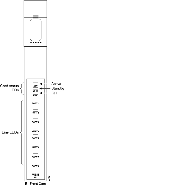
VISM Card LEDs
The VISM card uses the following three card status LEDs (see Figure 8-1) to indicate certain states:
•
•
–
–
–
•
The VISM card uses eight line status LEDs (see Figure 8-1) to indicate the following states of the eight T1 or E1 ports on the VISM back card:
•
•
•
–
–
–
Figure 8-1 VISM Front Card LEDs
VISM and PXM Display, Log, and Diagnostic Loopback Path CLI Commands
You can use the following commands to troubleshoot your VISM card:
•
•
•
Note
VISM Display Card CLI Command
Use the VISM dspcd command to display the following types of information about your current VISM card:
•
•
•
•
The following example shows the results of a typical dspcd command:
NODENAME.1.3.VISM8.a > dspcdModuleSlotNumber: 17FunctionModuleState: ActiveFunctionModuleType: VISM-8T1FunctionModuleSerialNum: SAK0331006PFunctionModuleHWRev: 0.0FunctionModuleFWRev: 2.0.0_11Nov01_2FunctionModuleResetReason: ?LineModuleType: LM-RJ48-8T1LineModuleState: PresentmibVersionNumber: 21configChangeTypeBitMap: CardCnfChng, LineCnfChngpcb part no - (800 level): 800-04399-01pcb part no - (73 level): 73-03618-01Fab Part no - (28 level): 28-02791-01PCB Revision: 08Daughter Card Information:Daughter Card Serial Number: SAK0331003Ppcb part no - (73 level): 73-03722-01Fab Part no - (28 level): 28-02905-01PCB Revision: 04PXM Display Log CLI Command
Use the PXM dsplog command to display useful information for troubleshooting your VISM card. The log is maintained by the PXM. A VISM entry is displayed in the log in the following format:
•
•
•
•
–
–
•
The following example shows the results of a typical dsplog command:
09/09/2001-02:09:01 03 cam VISM-6-9157VISM got time from PXMPXM Diagnostic Loopback Path CLI Commands
The VISM-8T1 and VISM-8E1 cards provide the capability for creating loopback paths for diagnostic purposes. Use the VISM and PXM diagnostic loopback CLI commands to troubleshoot your VISM cards. The following loopback configurations are possible:
•
•
Use the BERT and loopback functions to test the integrity of T1 and E1 lines. You can use the PXM cnfbert command on the PXM to perform the following actions:
–
–
–
–
•
•
•
PXM1E and PXM 45 Display CLI Commands
Refer to the Cisco MGX 8830, MGX 8850 (PXM45 and PXM1E), and Cisco MGX 8950 Command Reference, Release 4 for information on the following PXM1, PXM1E, and PXM45 card display commands.
VISM Alarms
Table 8-1 describes VISM T1 and E1 card alarms.
Table 8-1 VISM T1 and E1 Card Alarms
Link Failure—receive LOS 1
LOS1
AIS2
RAI3
RAI 3 returned on the transmit line.
Receive RAI 3
Yellow
RAI 3
None
—
Receive LOF4
—
AIS 2
RAI 3
RAI 3 returned on the transmit line.
Receive AIS 2
AIS 2
AIS 2
RAI 3
RAI 3 returned on the transmit line.
1 LOS = Loss of service.
2 AIS = Alarm indication signal.
3 RAI = Remote alarm indicator.
4 LOF = Loss of frame.
Refer to T1.403 for DS1 and G.704 for E1 definitions of alarm states. Alarms are propagated to the remote end over the ATM network in accordance with ATM specifications.
UNIX Snoop Trace Tool
Use the UNIX snoop trace tool to assist in diagnosing a problem. The snoop command can determine if there is any activity between the VISM and the call agent. The following example shows the command and a typical resulting terminal display:
snoop -x 42 -ta <ip address of CA> port <udp port of CA>E.g snoop -x 42 -ta vismvsc1 port 2427Symptoms and Solutions
This section includes possible solutions to the following possible symptoms:
•
•
•
•
•
•
•
•
•
VISM Card Did Not Become Active
Investigate the following possible causes for a VISM card that does not become active:
•
•
•
•
T1/E1 Configuration Mismatch
Use the PXM dspcds command to identify a T1/E1 configuration mismatch, as follows:
NODENAME.1.7.PXM.a > dspcdsSlot CardState CardType CardAlarm Redundancy---- ----------- -------- --------- -----------1.1 Empty Clear1.2 Empty Clear1.3 Empty Clear1.4 Empty Clear1.5 Mismatch VISM-8E1 Clear1.6 Empty Clear1.7 Active PXM1-OC3 Clear1.8 Empty Clear1.9 Empty Clear1.10 Empty Clear1.11 Empty Clear1.12 Empty Clear1.13 Empty Clear1.14 Empty Clear1.15 Empty Clear1.16 Empty Clear1.17 Empty Clear1.18 Empty Clear1.19 Empty ClearUse the PXM dspsmcnf command to identify a T1/E1 configuration mismatch, as follows:
NODENAME.1.7.PXM.a > dspsmcnfslot Card Rate Channel MIB FeatureNo. Type Control ized IMA MULTRKS Version Bits------ ---------- ------- ------- ------- ------- ------- -------1 ------> No configuration file exist for this slot <------2 ------> No configuration file exist for this slot <------3 VISM-8T1 Off Off Off Off 20 0x04 ------> No configuration file exist for this slot <------5 VISM-8T1 Off Off Off Off 20 0x06 ------> No configuration file exist for this slot <------9 ------> No configuration file exist for this slot <------10 ------> No configuration file exist for this slot <------11 ------> No configuration file exist for this slot <------12 ------> No configuration file exist for this slot <------13 ------> No configuration file exist for this slot <------14 ------> No configuration file exist for this slot <------17 ------> No configuration file exist for this slot <------18 ------> No configuration file exist for this slot <------19 ------> No configuration file exist for this slot <------20 ------> No configuration file exist for this slot <------21 ------> No configuration file exist for this slot <------22 ------> No configuration file exist for this slot <------25 ------> No configuration file exist for this slot <------26 ------> No configuration file exist for this slot <------27 ------> No configuration file exist for this slot <------28 ------> No configuration file exist for this slot <------29 ------> No configuration file exist for this slot <------30 ------> No configuration file exist for this slot <------Use the PXM dsplog command to show a card mismatch log entry, logged by VISM card on slot 5, as follows:
09/09/2001-00:01:47 05 dsplog VISM-6-9025VISM going to standby : Config. Mismatch between PXM and VISMUse the VISM dspcd command to display the following information:
NODENAME.1.5.VISM8.s > dspcdModuleSlotNumber: 5FunctionModuleState: MismatchFunctionModuleType: VISM-8E1FunctionModuleSerialNum: CAB12345678FunctionModuleHWRev: 0.13FunctionModuleFWRev: 2.2.10g.pmFunctionModuleResetReason: WatchDog timeout resetLineModuleType: MissingLineModuleState: Not PresentmibVersionNumber: 20configChangeTypeBitMap: CardCnfChng, LineCnfChngcardIntegratedAlarm: Clearpcb part no - (800 level): 800-03530-01pcb part no - (73 level): 73-03021-01Fab Part no - (28 level): 28-02492-01PCB Revision: 01Daughter Card Information:Daughter Card Serial Number: CAB12345678pcb part no - (73 level): 73-03022-01Fab Part no - (28 level): 28-02493-01PCB Revision: 01 value = 34 = 0x22 = '"'DSP Download Failure
Use the PXM dsplog command to determine if the minimum number (five) of the DSPs failed to download. The terminal displays results similar to the following:
NODENAME.1.7.PXM.a > dsplog01/01/2001-00:02:10 05 tDspmDl VISM-6-9193DSPM task errors : 6 DSPs failed to downloadIf the number of DSPs (six in the above case) is greater than five, the card will fail to be in the active state. If this condition happens repeatedly, replace the card.
Use the following PXM dspcds command, and the results, to determine the current state of VISM DSPs:
NODENAME.1.7.PXM.a > dspcdsSlot CardState CardType CardAlarm Redundancy---- ----------- -------- --------- -----------1.1 Empty Clear1.2 Empty Clear1.3 Empty Clear1.4 Empty Clear1.5 Failed VISM-8E1 Clear1.6 Empty Clear1.7 Active PXM1-OC3 Clear1.8 Empty Clear1.9 Empty Clear1.10 Empty Clear1.11 Empty Clear1.12 Empty Clear1.13 Empty Clear1.14 Empty Clear1.15 Empty Clear1.16 Empty Clear1.17 Empty Clear1.18 Empty Clear1.19 Empty ClearVISM Front Card/Back Card Mismatch
Use the following PXM dsplog command to investigate a possible VISM front card/back card mismatch:
NODENAME.1.7.PXM.a > dsplog01/01/2001-00:02:24 05 cmm VISM-6-9025VISM going to standby : Config. Mismatch between ASC and VISMV01/01/2001-00:02:24 05 cmm VISM-6-9023Mismatch Backcard01/01/2001-00:02:24 05 cmm VISM-6-9023Mismatch BackcardIn a mismatch condition, use the PXM dspcds command to display the following type of information:
NODENAME.1.7.PXM.a > dspcdsSlot CardState CardType CardAlarm Redundancy---- ----------- -------- --------- -----------1.1 Empty Clear1.2 Empty Clear1.3 Empty Clear1.4 Empty Clear1.5 Mismatch VISM-8E1 Clear1.6 Empty Clear1.7 Active PXM1-OC3 Clear1.8 Empty Clear1.9 Empty Clear1.10 Empty Clear1.11 Empty Clear1.12 Empty Clear1.13 Empty Clear1.14 Empty Clear1.15 Empty Clear1.16 Empty Clear1.17 Empty Clear1.18 Empty Clear1.19 Empty ClearUse the VISM dspcd command to display the following types of information:
NODENAME.1.5.VISM8.s > dspcdModuleSlotNumber: 5FunctionModuleState: MismatchFunctionModuleType: VISM-8E1FunctionModuleSerialNum: CAB0246014PFunctionModuleHWRev: 0.0FunctionModuleFWRev: 2.2.10g.pmFunctionModuleResetReason: Reset by ASC from Cell BusLineModuleType: LM-RJ48-8T1LineModuleState: InvalidmibVersionNumber: 20configChangeTypeBitMap: CardCnfChng, LineCnfChngcardIntegratedAlarm: Clearpcb part no - (800 level): 800-04399-01pcb part no - (73 level): 73-03618-01Fab Part no - (28 level): 28-02791-01PCB Revision: 05Daughter Card Information:Daughter Card Serial Number: CAB024601FFpcb part no - (73 level): 73-03722-01Fab Part no - (28 level): 28-02905-01PCB Revision: 02 value = 34 = 0x22 = '"'Cannot Use the cc Command to Access a VISM Card
Use the PXM dspcds command to verify if the VISM card is in the active or standby state. If the VISM card is not in the active or standby state, you cannot use the cc command to access the card.
VISM Card Resets Intermittently
Investigate the following possibilities to determine why the VISM card is resetting intermittently:
•
•
VISM Card Does Not Accept a Firmware Download
There must be a VISM card in the slot to which firmware is being downloaded. Ensure that the VISM card is seated in the slot, and that it is making electrical contacts to the backplane.
The card must be in either the active or boot state. Confirm this is the case and try again.
Echo Is Heard on a Voice Call
Ensure that the call has the ECAN feature enabled. If the echo delay is longer than the provision tail length, ECAN does not work. Use the VISM cnfecantail command to configure a larger value for the tail length.
VISM Card LEDs Are Not Lighted
The VISM card may not be inserted completely in the slot. Ensure that the VISM card is seated in the slot correctly, with top and bottom half portions of the VISM card making electrical contact with the backplane.
Firmware Does Not See the Card Insert Bit Status As Set
This symptom can also indicate a bad VISM card or bad MGX slot.
![]()
![]()
![]()
![]()
![]()
![]()
![]()
![]()
Posted: Thu Jun 10 16:30:42 PDT 2004
All contents are Copyright © 1992--2004 Cisco Systems, Inc. All rights reserved.
Important Notices and Privacy Statement.