|
|

Table Of Contents
VISM/VISM-PR Card Clocking Options
PXM1 Card as Primary Clocking Source
VISM-PR Card as Clocking Source
PXM1E or PXM45 Card as Primary Clocking Source
Revertive and Nonrevertive Clocking
VISM/VISM-PR Card Clocking Options
An MGX 8000 Series platform, consisting of PXM and VISM cards, should have one primary clocking source. To avoid conflicts and to ensure proper operation, the settings for clocking options in both card types are considered together. You must use one of the following primary clocking source options:
•
PXM1, PXM1E, and PXM45 cards—Provide clocking for all VISM/VISM-PR cards in the chassis.
•
•
This section contains the following topics;
•
•
•
•
•
PXM1 Card as Primary Clocking Source
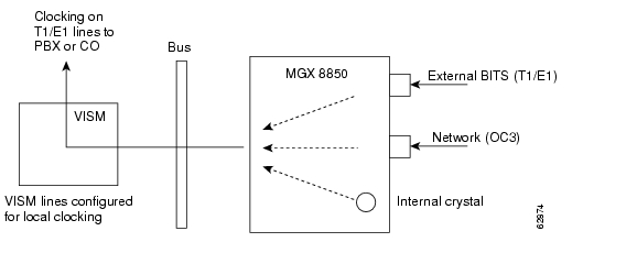
Figure 0-1 shows the PXM card primary clocking source option in which the clock source originates at the PXM side of the VISM/PXM interface.
Figure 0-1 VISM Configured for Local Clocking
The PXM1 card option allows you to configure the clocking source origination from one of the following sources:
•
•
•
The internal crystal is the default and is set as the primary clock source automatically when power is applied to the chassis.
To use one of the other two clocking sources, complete the following steps:
Step 1
Step 2
The PXM card option makes the PXM the clock source for the all cards in the chassis. The VISM cards then use this clocking to provide clocking for their associated T1 or E1 lines. Refer to Chapter 7, "CLI Commands," for more information on VISM commands.
Refer to the Cisco MGX 8850 Installation and Configuration Guide and the Cisco MGX 8000 Series Switch Command Reference for information on the following PXM card clocking commands:
•
•
•
•
•
•
•
VISM Card as Clocking Source
You can configure the VISM card as a primary or secondary clocking source.
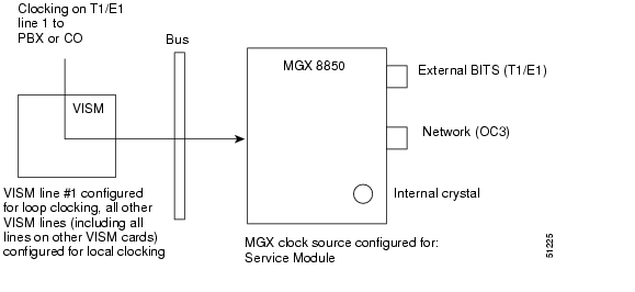
Figure 0-2 shows the VISM card primary clocking source option in which the clock source originates at the VISM side of the VISM/PXM1 interface.
Figure 0-2 VISM Configured for Loop Clocking
The VISM card option originates clocking from one of the T1 or E1 lines on one of the VISM cards.
To configure the VISM card as the primary or secondary clocking source, complete the following steps:
Step 1
Step 2
All of the lines must be configured for local clocking.
Step 3
Step 4
cvgmgx1a.1.7.PXM.a > cnfclksrc <slot.port> PReplace <slot.port> with the VISM card slot number and line number 1. The P indicates that the VISM card is configured as a primary clocking source.
Note
Step 5
The following example shows the service module as the clocking source.
cvgmgx1a.1.7.PXM.a > dspclkinfo****** Clock HW registers ********SEL_T1 = t1 SEL100 = ON SEL120 = OFF SEL75 = OFFNOEXTCLK = ON NOEXTCLK2 = OFFpriMuxClockSource = SERVICE_MODULE_PRI_CLKprevPriMuxClockSource = INTERNAL_OSCprimaryInbandClockSourceLineNum = 1secMuxClockSource = INTERNAL_OSCprevSecMuxClockSource = INTERNAL_OSCsecondaryInbandClockSourceLineNumber = 1currentClockSetReq = primarycurrentClockHwStat = primaryStratumLevel = STRATUM4PreviousClockHwStat = noneextClock1Present = NoextClock2Present = NoextClkConnectorType = RJ45extClkSrcImpedance = 100 Ohmsnternal Clock Status=0, Primary Clock Status=0Secondary Clock Status=0, Last inband Clock State=0last Inband Clock state= 0, Last External Clock Present = 1Last External Clock2 Present = 1Step 6
cvgmgx1a.1.7.PXM.a > cnfclksrc <slot.port> SReplace <slot.port> with the VISM card slot number and line number 1. The S indicates that the VISM card is configured as a secondary clocking source.
Note
Step 7
The following example shows the service module as a secondary clock source.
cvgmgx1a.1.7.PXM.a > dspclkinfo****** Clock HW registers ********SEL_T1 = t1 SEL100 = ON SEL120 = OFF SEL75 = OFFNOEXTCLK = ON NOEXTCLK2 = OFFpriMuxClockSource = SERVICE_MODULE_PRI_CLKprevPriMuxClockSource = SERVICE_MODULE_PRI_CLKprimaryInbandClockSourceLineNum = 1secMuxClockSource = SERVICE_MODULE_SEC_CLKprevSecMuxClockSource = INTERNAL_OSCsecondaryInbandClockSourceLineNumber = 1currentClockSetReq = primarycurrentClockHwStat = secondaryStratumLevel = STRATUM4PreviousClockHwStat = primaryextClock1Present = NoextClock2Present = NoextClkConnectorType = RJ45extClkSrcImpedance = 100 OhmsInternal Clock Status=0, Primary Clock Status=0Secondary Clock Status=0, Last inband Clock State=0last Inband Clock state= 0, Last External Clock Present = 1Last External Clock2 Present = 1
VISM-PR Card as Clocking Source
The VISM-PR card allows you to configure primary and secondary clocking from the following sources:
•
•
•
To configure the VISM-PR card as the primary or secondary clocking source, complete the following steps:
Step 1
Step 2
All of the lines must be configured for local clocking.
Step 3
Step 4
Note
Step 5
You cannot delete a line that is configured as the clock source. You must first configure the line to not be the clock source, and then you can delete the line.
Refer to Chapter 7, "CLI Commands," for more information on VISM commands.
PXM1E or PXM45 Card as Primary Clocking Source
Use the cnfncdpclksrc command to configure the PXM1E or PXM45 card as the primary clock source. Refer to the Cisco MGX 8850 Installation and Configuration Guide and the Cisco MGX 8000 Series Switch Command Reference for configuration instructions. Use the following commands to display and verify your configuration:
•
•
Revertive and Nonrevertive Clocking
Clocking can be either revertive or nonrevertive. If your MGX switch is configured for a clock source from a BITS source or PXM line source and the source line goes into the alarm state, a revertive or nonrevertive recovery occurs.
•
•
Revertive and nonrevertive clocking depends upon the processor module back card used and the clocking source specified. See Table 0-1 to determine if your clocking is revertive or nonrevertive in your network configuration.
To make a nonrevertive clock source usable after it has failed, you must use the cnfclksrc command to remove the configuration of that particular clock source, and then use the cnfclksrc command again to configure it back. Refer to Chapter 7, "CLI Commands," for more information on CLI commands.
![]()
![]()
![]()
![]()
![]()
![]()
![]()
![]()
Posted: Thu Jun 10 16:44:36 PDT 2004
All contents are Copyright © 1992--2004 Cisco Systems, Inc. All rights reserved.
Important Notices and Privacy Statement.