|
|

This chapter describes how to mount the chassis and install the circuit cards.
Make sure that you have the following standard tools before beginning the installation:
The Cisco MGX 8260 chassis mounts in a standard 19-inch or 23-inch equipment rack. Before starting the installation procedure, check that you have the necessary hardware components for your system. Circuit cards should already have been installed before shipment. Table 4-1 lists the hardware components available for the MGX 8260. Your system may or may not use all of these components.
| Part Number | Description | MGX 8260 Slot Locations |
|---|---|---|
AC-DC-EXTPSS | MGX 8260 Power Rectifier | — |
BSCFC-6T3 | Front card for Broadband Service Card (BSC); provides TDM switching for 6 channelized DS3 lines | 9, 10 |
DMCFC-6T3 | Front card for Distribution Matrix Card (DMC); provides processing for 6 channelized DS3 lines | 7, 8 |
MGX8260 | System chassis and accessory kit | — |
NSCFC-8DSP | Front card for Narrowband Service Card (NSC); provides DSP processing for up to 8 channelized T1/E1 lines, including voice, G.711, echo, VAD, and CNG functions | 1-8, 11-16 |
NSCFC-16DSP | NSC front card providing DSP processing for up to 16 channelized T1/E1 lines, including voice, G.711, echo, VAD, and CNG functions | 1-8, 11-16 |
NSCFC-8TDM | NSC front card providing TDM switching for up to 8 channelized T1/E1 lines | 1-8, 11-16 |
NSCFC-16TDM | NSC front card providing TDM switching for up to 16 channelized T1/E1 lines | 1-8, 11-16 |
OC3MMBC-4 | SCC back card providing 4 OC-3 Multi-Mode Fiber (MMF) interfaces | 11-16 |
OC3SMIBC-4 | SCC back card providing 4 OC-3 Single-Mode Fiber Interface (SMFI) | 11-16 |
SCC5FC-4FE/B | 5 Gps SCC front card supports 4 FE ports | 9, 10 |
SCC5FC-4OC3/B | 5 Gps SCC front card supports 4 OC-3 ports | 9, 10 |
SCCBC-4FE | SCC back card providing NMS ports and four 100BASE-T network interface ports | 9, 10 |
T1E1BC-50NR | NSC back card providing RJ-21, 50-pin, 100-ohm, T1/E1 interfaces | 1-8, 11-16 |
T1E1BC-RED | NSC back card providing 1:N redundancy support | 1-8, 11-16 |
T1E1BC-RJ48 | NSC back card providing 16 E1 120-ohm RJ-48 interfaces | 1-8, 11-16 |
T3E3BC-6DSX | BSC back card providing 6 Tx and Rx coaxial T3 interfaces | 11-16 |
To complete the setup procedure, you also need a VT100-compatible terminal or a PC running terminal emulation software.
A new chassis is shipped with cards installed. Unless your operating procedures require card removal (for example, to reduce chassis weight), leave the cards installed. If you must remove the front cards, leave the back cards installed. For more information, refer to the "Installing Front Cards" section.
To install the Cisco MGX 8260 chassis, follow these steps:
Step 1 Make sure that your racks are secured to the floor.
Step 2 Visually inspect the mounting brackets to make sure they fit the rack width you are using. The chassis ships with mounting brackets separately packed.
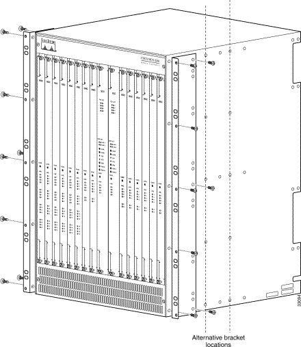
Step 3 Install the mounting brackets to suit your system using the short-length, flat head screws supplied with the brackets. Position the long side of the bracket against the chassis for a 19-inch rack, or the short side against the chassis for a 23-inch rack. With either width, you can mount the brackets flush with the front of the unit, or recessed by 5 inches or 8 inches. Figure 4-1 shows the brackets mounted for a 19-inch rack.
 |
Caution Do not use substitute screws for the mounting brackets. Longer screws can damage the chassis or circuit cards. |
 |
Warning To prevent bodily injury when mounting or servicing this unit in a rack, mount the MGX 8260 at the bottom of the rack if the rack will include only one MGX 8260 node. If mounting the MGX 8260 in a partially filled rack, load the rack from the bottom to the top with the heaviest component at the bottom of the rack. If the rack is provided with stabilizing devices, install the stabilizers before mounting or servicing the MGX 8260 in the rack. |
Step 4 Using the mounting bracket and at least 12 screws, mount the Cisco MGX 8260 chassis in the equipment rack. (See Figure 4-2.)

Step 5 Use a double crimp tool to secure an 8 AWG ground wire in a standard-barrel 2-hole ground lug. The MGX 8260 has two sets of ground terminals. Use an 11/32-inch nut driver to tighten the locking nuts onto the lug at one set of terminal posts.
 |
Note Do not connect more than one ground wire to the MGX 8260 chassis. Connect the ground wire to one set of terminals only. (See Figure 4-3.) |
|
Note If insulated, the ground wire must be green, with one or more yellow stripes, to comply with industry standard color schemes. |
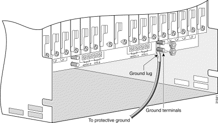
Step 6 Connect the other end of the ground wire to a building ground point near the chassis.
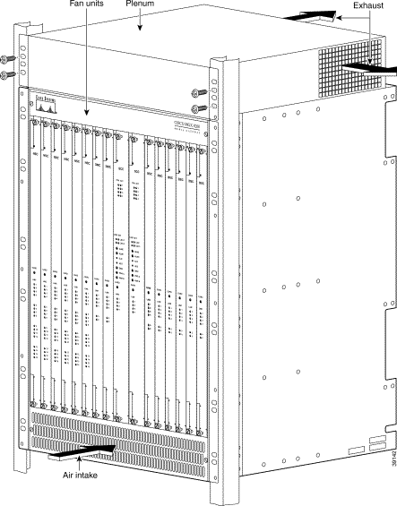
The exhaust plenum is an MGX 8260 accessory that redirects airflow from the top of the chassis to the rear.
|
Note The plenum must be installed on an MGX 8260 that will be situated in a lower rack location with other equipment above the chassis. The plenum is not required for an MGX 8260 that is located in a rack with no equipment above the chassis, such as the top of an equipment rack. |
To install the exhaust plenum, follow these steps:
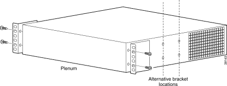
Step 1 Attach the mounting brackets to the plenum. (See Figure 4-4.) The brackets can be located for flush or offset mounting to correspond with the chassis mountings. Use the four pan head screws provided with the brackets.
Step 2 Place the plenum over the MGX 8260 chassis. (See Figure 4-5.)
Step 3 Secure the plenum to the rack using the screws provided.
The Cisco MGX 8260 chassis holds front and back cards connected to a midplane. Table 4-1 shows the logical placement of cards within the MGX 8260.
The MGX 8260 typically ships with all cards installed. If your installation scenario requires you to remove front cards to reduce chassis weight, use the following procedure to reinstall the front cards.
|
Caution Observe standard electrostatic discharge (ESD) precautions before handling, inserting, or removing cards. |
Step 1 Wear an antistatic wriststrap and connect it to a ground point on the chassis or equipment rack.
Step 2 Locate the correct SCC for your system. (See Table 4-1.)
If your system uses redundant controllers, both must be identically equipped with the same type of broadband interface module (BIM), i.e., Fast Ethernet or SONET (OC-3).
|
Caution Handle the cards gently. Bending or forcing the cards can cause permanent damage. |
Step 3 From the front of the chassis, install an SCC in slot 9. (See Figure 4-6.) With the extraction levers straight out, slide the card into the slot until the top and bottom levers engage and roll over the lip of the chassis. Seat the card firmly into the backplane by pressing firmly inward on the extraction levers.
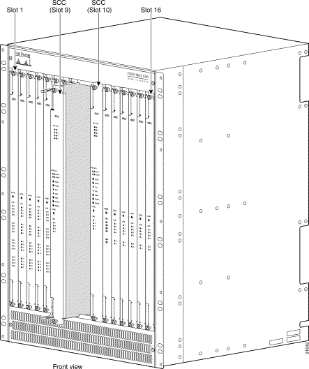
Step 4 Secure the card at the top and bottom by tightening the captive mounting screws.
Step 5 If your system features a redundant SCC, install the redundant card in slot 10 and secure it.
Step 6 If your system has switched DS3 interfaces, install and secure up to six BSCs in slots 11 through 16.
Step 7 If your MGX 8260 has DS3 lines with M13 mapping, install and secure one or two DMCs. If there is an SCC in slot 9, install a DMC in slot 7; If there is an SCC in slot 10, install a DMC in slot 8.
|
Note DMCs only work in slots 7 or 8 and must be paired with SCCs in slots 9 or 10, respectively. |
Step 8 If your system has T1or E1 interfaces, install and secure up to fourteen NSCs in slots 1 to 6 or 11 to 16. For systems without DMC cards, you can install up to two additional NSCs in slots 7 and 8.
Step 9 Remove your wriststrap.
|
Note When you have completed installation of all front cards, be certain that blank panels are properly installed in any slots unoccupied. These panels are required for EMI compliancy and air flow. |
The Cisco MGX 8260 chassis holds front and back cards. Systems typically ship with all cards installed. If your installation scenario requires you to remove back cards to reduce chassis weight, use the following procedure to reinstall back cards:
Step 1 Connect your wriststrap to a ground point on the chassis or equipment rack.
Step 2 Locate the correct SCC back card for your system. (See Table 4-1.)
If your system uses redundant controllers, both must be identically equipped with the same type of broadband interface module (BIM), i.e., Fast Ethernet or SONET (OC-3).
|
Caution Handle the cards gently. Bending or forcing the cards can cause permanent card damage. |
Step 3 From the rear of the chassis, install an SCC back card behind an SCC front card, in slot 9 or 10. (See Figure 4-7 and Figure 4-8.) It's important to properly align the card with the midplane socket, so gently insert the card straight through the guides until it just makes contact with the socket. Then using your thumbs, apply pressure approximately one inch from the top and at the middle of the card until it slides into place. Press firmly inward on the card extraction levers to fully seat the card in the midplane.
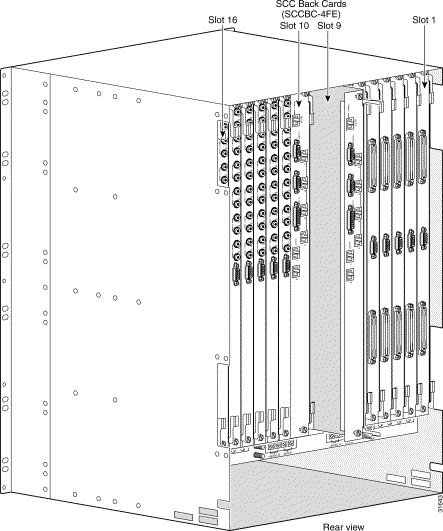

Step 4 Secure the SCC back card at the top and bottom with the captive mounting screws.
Step 5 If your system uses SCC redundancy, install the second SCC back card in the remaining slot,
either 9 or 10.
Step 6 If your system has switched DS3 interfaces, install and secure DS3 back cards behind each BSC front card.
Step 7 If your MGX 8260 has DS3 lines with M13 mapping, install and secure DS3 back cards behind each DMC front card (slots 7 and 8).
Step 8 If your system has T1 or E1 interfaces:
a. Locate the correct NSC back cards for your system. (See Table 4-1.)
b. Install and secure the appropriate back cards behind each primary NSC front card. If your system configuration supports NSC N+1 redundancy, install the NSC redundant back card (T1E1BC-RED) behind the designated secondary NSC.
Step 9 Remove your wriststrap.
|
Note When you have completed installation of all back cards, be certain that blank panels are properly installed in any slots unoccupied. These panels are required for EMI compliancy and air flow. |
![]()
![]()
![]()
![]()
![]()
![]()
![]()
![]()
Posted: Sat Sep 28 22:21:03 PDT 2002
All contents are Copyright © 1992--2002 Cisco Systems, Inc. All rights reserved.
Important Notices and Privacy Statement.