|
|

 |
Tip An interactive version of these worksheets also is available at http://www-tac.cisco.com/Support_Library/Hardware/WAN_Switches_and_Modules/IGX_8400/ |
Before you install the system, verify that you have adequate power for all cards to be installed in the chassis. Using Table 2-1 and Table 2-2, follow the instructions listed below, or use the interactive version, to calculate your power budget for each node to be installed in the network.
Table 2-1 Cisco IGX 8400 Series Power Consumption Worksheet
| Line | IGX Card | Card Power | Quantity | Total Power |
|---|---|---|---|---|
Fill in the blank cells in Table 2-1 using the following rules:
Step 2 Multiply the IGX card quantity by the card wattage listed in the Card Power column, and enter the result in the Total Power column.
Step 3 Total the Quantity column and enter the result in the Total Number of Cards row (line 20).
Step 4 Confirm that the total number of cards does not exceed the allowable number of cards for your chassis. The IGX 8410 allows 8 cards, the IGX 8420 allows 16 cards, and the IGX 8430 allows 32 cards.
Step 5 Total the Total Power column and enter the result in the Total Power Demand row (line 21).
Step 6 Proceed to Step 1 for Table 2-2.
Table 2-2 Cisco IGX 8400 Series Power Supply Worksheet
| Line | Power Supply | Rating | Quantity | Total Power |
|---|---|---|---|---|
Fill in the blank cells in Table 2-2 using the following rules:
Step 2 Enter the number of power supply units (PSUs) to be installed in the Quantity column for all AC Power Supply and DC Power Supply rows (lines 22, 25, and 28). The allowable values are:
Step 3 Multiply the number in the Quantity column by the value in the Rating column, and enter the result in the Total Power column (for lines 22, 25, or 28).
Step 4 Compare the total power number (lines 22, 25, or 28) to the shelf rating (lines 23, 26, or 29). The available power is the lowest of these two numbers. For example, if the total power number is higher than the shelf rating, the available power will equal the shelf rating.
Step 5 Enter the available power in the Available power row (lines 24, 27, or 30) and in the Total shelf power row (line 31).
Step 6 Subtract the Total Power Demand (line 21) from the Total shelf power (line 31), and enter the result in the Total shelf power - total power demand row (line 32).
|
Tip If the number in the Total shelf power - total power demand row (line 32) is negative, the system is short of power. Either add more power by increasing the number of power supply units as applicable (if possible) or decrease the power demand by removing cards from the chassis. |
Before you install the system, verify that all the required parts are present and in good condition. If anything is missing or damaged, contact your sales representative.
Check the cabinet for the following inventory:
Check the cabinet for the following inventory:
Make sure that all purchased cards are present. Check the number and type of cards shipped against the number and type of card purchased. In Table 2-3, the column on the left lists the front cards. The column on the right lists the possible corresponding back cards. Check off each card type as you inventory them.
An inventory list of the installed cards is shipped with the unit. The list includes each card's serial number, revision number, and slot number (serial and revision numbers are also found on the solder side of each card). Check for the presence of any other items on the shipping list. After verifying that the correct cards are present, tape a copy of the inventory list to the cabinet door or tape into your network documentation.
 |
Warning This unit is intended for installation in restricted access areas. A restricted access area can be accessed only through the use of a special tool, lock and key, or other means of security. To see translations of this warning, refer to the Regulatory Compliance and Safety Information document that accompanied this product. |
The site must satisfy the following requirements:
The standalone IGX 8410 node requires a floor area 19.9 inches (50.5 cm) wide and at least
47 in. (180 cm) deep. This depth allows for opening the front door. Sufficient clearance around the cabinet must also be provided for access to the front and back of the cabinet while the door is open. The rack-mount IGX 8410 node requires 24.44 inches of vertical space.
A standalone IGX 8420 or IGX 8430 node requires a floor area 19.9 inches (50.5 cm) wide and at least 47 in. (119.4 cm) deep. This spacing lets you open the front door. Clearance around the cabinet must also allow access to the front and back of the cabinet while the door is open. The rack-mount IGX 8430 requires 32 in. (81.3 cm) of vertical space. The rack-mount IGX 8430 node requires 55 in. (139.7 cm) of vertical space.
In a rack-mount system, the mounting rail pattern follows the EIA standard of 56 in. (or
32 rack-mount units). For displacement information for the IGX components and other components in the Cisco cabinet, refer to "General IGX 8410 Switch Specifications."
The IGX operating environment should be as follows:
Temperature and humidity range: 0 to 40\xb0 C (32 to 104\xb0 F) for normal operation, 50\xb0 C (122\xb0 F) for up to 72 hours. 10 to 85 percent relative humidity, noncondensing.
Shock—The switch withstands 10 G, 10 ms at 1/2 sine wave.
Vibration—The switch withstands 1/4 G, 20 to 500 Hz.
For AC power use, an AC power source must be available within 6 ft (1.8 m) of the IGX node. For systems using a DC source, Cisco does not supply the DC power cord, so the user or installer determines the cord length and the distance to the DC source. The wire should be 10-12 AWG or 4 square mm.
A fully loaded, AC-powered IGX 8410 node dissipates up to 3,500 BTUs (1 kw hour). A DC-powered IGX 8410 node can dissipate up to 2720 BTUs.
A fully loaded, AC-powered IGX 8420 node dissipates up to 4300 BTUs (1 kw hour). A DC-powered IGX 8420 can dissipate up to 3600 BTUs.
A fully loaded, AC-powered IGX 8430 node dissipates up to 8600 BTUs (1 kw hour). A DC-powered IGX 8430 node can dissipate up to 6800 BTUs.
A fully loaded IGX 8410 enclosure can weigh up to 173 lb (79 kg). A fully loaded IGX 8420 enclosure can weigh up to 250 lb (112.5 kg). A fully loaded IGX 8430 enclosure can weigh up to 500 lb (225 kg).
 |
Caution If you move a Cisco cabinet, do not push it at its sides. Push at the front or back. |
Raised flooring with sufficient under-floor space to house the cables is recommended.
An IGX node is either mounted in a rack or free-standing (in a standalone cabinet). The location of the IGX node should accommodate the routing of the data cables and the termination of the telephone company's or common carrier's circuits.
The IGX 8410 node has one mounted wrist strap at the front and one at the back of the cabinet. Personnel with access to the IGX 8410 cards should put on a wrist strap before handling the cards. An IGX 8420/8430 node does not ship with a wrist strap.
To provide some protection against seismic activity, the feet and wheels of the IGX standalone cabinets can be removed to permit the cabinet to be bolted to a concrete floor or to a structural member in the floor.
In cabinets supplied by Cisco, provisions are available for seismic anchoring. Holes exist in the upper and lower corners for 3/8- or 1/2-in. bolts. Also, an optional stability plate can be purchased with the Cisco cabinet. The stability plate is bolted to the floor, then the Cisco cabinet is bolted to the stability plate. The "Seismic Anchoring for the Cisco Rack" section contains instructions for installing the seismic stability plate.
The following paragraphs contain general safety information and information on telecommunications safety requirements.
|
Warning Before working on equipment that is connected to power lines, remove jewelry (including rings, necklaces, and watches). Metal objects will heat up when connected to power and ground and can cause serious burns or weld the metal object to the terminals. To see translations of this warning, refer to the Regulatory Compliance and Safety Information document that accompanied this product. |
|
Warning Do not work on the system or connect or disconnect cables during periods of lightning activity. To see translations of this warning, refer to the Regulatory Compliance and Safety Information document that accompanied this product. |
|
Warning Before working on a system that has an on/off switch, turn OFF the power and unplug the power cord. To see translations of this warning, refer to the Regulatory Compliance and Safety Information document that accompanied this product. |
|
Warning This equipment must be installed and maintained by service personnel as defined by AS/NZS 3260. Incorrectly connecting this equipment to a general-purpose outlet could be hazardous. The telecommunications lines must be disconnected 1) before unplugging the main power connector or 2) while the housing is open, or both. To see translations of this warning, refer to the Regulatory Compliance and Safety Information document that accompanied this product. |
|
Warning The plug-socket combination must be accessible at all times, because it serves as the main disconnecting device. To see translations of this warning, refer to the Regulatory Compliance and Safety Information document that accompanied this product. |
|
Warning A readily accessible two-poled disconnect device must be incorporated in the fixed wiring. To see translations of this warning, refer to the Regulatory Compliance and Safety Information document that accompanied this product. |
|
Warning When installing or replacing the unit, the ground connection must always be made first and disconnected last. To see translations of this warning, refer to the Regulatory Compliance and Safety Information document that accompanied this product. |
The following safety requirements must be observed:
This section lists the requirements that relate to electrical power and grounding. These requirements cover installations at central office (CO) and private enterprise locations.
For an AC-powered system, verify that the node's power comes from a dedicated AC branch circuit. The circuit must be protected by a dedicated, two-pole circuit breaker. The circuit breaker must have a rated current and trip delay that is greater than those of the IGX circuit breaker. Cisco Systems recommends the following:
The IGX 8420 and IGX 8430 nodes use a 20A, 2-pole circuit breaker for each AC input. The manufacturer of this circuit breaker is ETA, and the ETA part number for the circuit breaker is 8340-F120-P1P2-B2H020A. The IGX 8410 node uses a 15A, 2-pole AC circuit breaker on each input. This circuit breaker comes from either ETA (part number 8340-F120-P1P2-B2H015A) or Airpax (part number IEGH11-1-62-15.0-91V).
|
Warning This product relies on the building's installation for short-circuit (overcurrent) protection. Ensure that the protective device is rated not greater than: 120 VAC, 15A U.S. (240 VAC, 10A international) To see translations of this warning, refer to the Regulatory Compliance and Safety Information document that accompanied this product. |
For a DC-powered system, verify that the node's power comes from a dedicated DC branch circuit. The circuit must be protected by a dedicated circuit breaker. The circuit breaker must have a rated current and trip delay that is greater than those of the IGX circuit breaker. Cisco Systems recommends that the site have a dedicated 25A, 1-pole circuit breaker with a medium trip delay at each branch circuit.
The DC-powered nodes use a 25A, 1-pole circuit breaker with a short trip delay on each -48V input. The manufacturer of this circuit breaker is ETA, and the ETA part number is 8340F110P1K1A2H00025.
|
Warning This product relies on the building's installation for short-circuit (overcurrent) protection. Ensure that the protective device is rated not greater than: 25A minimum, 60VDC To see translations of this warning, refer to the Regulatory Compliance and Safety Information document that accompanied this product. |
An AC power source must be available within 6 ft (1.8 m) of the system and easily accessible. Before turning on the power, verify that the power supplied to the node comes from a dedicated branch circuit.
The power receptacles to which the node connects must be of the grounding type. The grounding conductors that connect to the receptacles should connect to protective earth at the service equipment.
Only a 48-VDC supply that complies with the Safety Extra Low Voltage (SELV) requirements of
EN 60950 can connect to the IGX DC input.
For DC supply connections, consult local and national codes for proper conductor sizing. The conductors must be suitable for 20 A. Wiring that is 10 to 12 AWG (4 sq mm) is adequate.
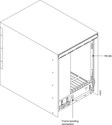
To maintain the full EMI and EMC integrity of this equipment, it must be bonded to an integrated ground plane or an isolated ground plane network. In addition, the front card faceplate must be properly installed. The purpose of this is to mitigate the damaging effects to equipment from electrostatic discharge and lightning. Refer to the latest edition of ITU Recommendation K.27 or Telcordia Technologies GR-1089-CORE requirements to ensure that the correct bonding and grounding procedures are followed. As recommended in these documents, a frame bonding connection is provided on the cabinet supplied by Cisco for rack-mounted systems and on the standalone cabinets.
Refer to the "Making the Frame Bonding (Ground) Connection" section for information on the locations of the frame bonding connections and how to make a connection.
Except for the AC power supply module, every module in a rack-mount system relies on the rack itself for grounding. Therefore, the rack must be properly connected to protective earth before operating the system.
A DC-powered IGX node must have grounding conductors that connect at two separate locations, as follows:
The telecommunications requirements might be relevant to a private network connected to the public, switched networks in some international service areas.
 |
Note Cables must be attached so that their securing bolts are tightened such that a screwdriver is needed for removal. |
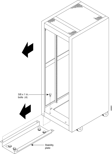
This section describes installing the Cisco cabinet with the optional stability plate for seismic anchoring. If the stability plate is not present, go to either the "IGX 8410 Enclosure Installation" section or the "IGX 8420 or IGX 8430 Enclosure Installation" section.
To set up the Cisco cabinet with the stability plate:
Step 2 Remove the stability plate from the base of the Cisco cabinet. Save the nuts and bolts.
Step 3 With the user-provided anchoring bolts, attach the stability plate to the floor.
Step 4 Roll the Cisco cabinet over the stability plate, as Figure 2-2 illustrates.
Step 5 Using the nuts and bolts from the shipping setup, secure the Cisco cabinet to the stability plate.
Installing an IGX 8410 switch requires the following tools and equipment:
The installation steps consist of placing the standalone IGX 8410 node at its operating location, unpacking it, and verifying the integrity of the enclosure and power connections. Note that the cabinet is 19.9 in. wide.
After the system is at its operational location, follow the steps for connecting power. If the system has an AC power source, go to the "AC Power Connections" section. If the system has a DC power source, go to the "DC Power Connections" section.
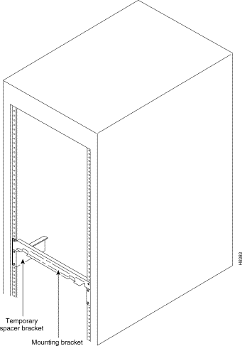
The rack-mount IGX 8410 node fits in a 19-in. (48.25-cm) rack with a minimum of 17.75 in. between rails. For mounting the chassis in a rack, brackets are attached to the front of the chassis. A pair of mounting brackets are attached at the back of the chassis after it is placed in the rack. Brackets for a mid-rack mounting also come with the kit.
To support the weight of the IGX 8410 node during installation, Cisco includes two temporary spacer brackets and a temporary mounting bracket. You remove these pieces after installation. The spacer brackets stabilize the rack. Also, the temporary mounting bracket together with the spacer brackets create a partial shelf onto which you can slide the node. These pieces support the system while you secure the permanent front and back mounting brackets to the rack.
|
Caution If an IGX node is mounted in a cabinet, be sure that an unrestricted air flow is available in and out of the enclosure. |
To install an IGX 8410 node in a rack:
Step 2 At the front of the rack, attach the temporary spacer bracket and temporary mounting brackets so that the uppermost portion of these pieces are at the bottom of the intended location of the IGX 8410 node. Figure 2-4 shows a temporary spacer and mounting bracket in a cabinet supplied by Cisco.
|
Caution If you must move a Cisco cabinet to install an IGX switch, do not push the cabinet at its sides. Instead, grip the cabinet at the front or back edges to maneuver it to the setup location. |
Step 3 Position the IGX 8410 node in front of the cabinet. This position should be such that the back of the IGX card cage faces the front of the rack. If you have not already done so, remove the foam strips from the sides, front, and back.
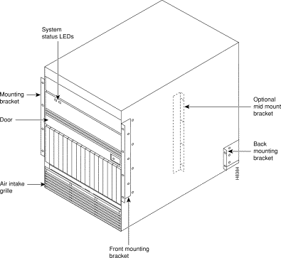
Step 4 Remove the attached mounting brackets (filler plates) for the standalone version. The mounting brackets for the rack-mount go in these places. See Figure 2-5 for the locations of the mounting brackets.
Step 5 Attach the front mounting brackets to the IGX 8410 node.
|
Caution An IGX 8410 node requires two or three people to lift it into the rack. |
Step 6 This step requires one person on each side of the IGX card cage. Lift and slide the card cage into the rack at the front of the rack. Slide the IGX 8410 node to the back and rest the rear of the system on the temporary mounting brackets and spacer.
Step 7 Secure the front bracket (or mid-mount bracket) to the rack. The mid-mount brackets require the threaded rolling screws that the IGX 8410 kit includes. Attach the IGX 8410 node to the rack with eight #10-32 machine screws.
|
Caution Make sure that mounting the equipment does not create a hazardous condition due to uneven mechanical loading. The equipment rack should be securely supported. |
Step 8 Attach the permanent rear mounting brackets to the rack.
Step 9 Remove the temporary mounting brackets and temporary spacer bracket.
Step 10 If this is a DC-powered system, go to the "DC Power Connections" section.
Step 11 Go to the procedures in "Installing the IGX."
Installing an IGX 8420 or IGX 8430 node requires the following tools and equipment:
Rack-mount systems ship with the parts described in the assembly instructions.
Because Cisco standalone systems ship with all components installed in the cabinet, the installation steps consist of placing the unit at its operational location, unpacking it, and verifying the structural and power connection integrity before turning on the power. Note that a standalone cabinet is 19.9-in. wide. The adjustable levelers require a 5/8-in. wrench. If the system has an AC power source, go to the "AC Power Connections" section. If the system has a DC power source, go to the "DC Power Connections" section.
The rack-mount IGX 8420 node fits in a 19-in. (48.25-cm) rack. The front of each assembly has flanges that serve as the front mounting brackets. The assembly kit contains other brackets for different mounting setups. The following order of component installation is the most convenient and efficient. For some of these components, separate sections follow with detailed installation steps.
Note that the vertical spacing between components, such as the card cage and fan tray, must be in the range 0.047-0.077 in. (0.119-0.196 cm).
The miscellaneous parts kit for rack systems contains brackets for both a Cisco cabinet and a user-supplied rack. The kit includes mid-mount brackets for open racks.
The rear-mount brackets attach to the rear vertical rail in a Cisco cabinet. Each of these brackets has a horizontal flange upon which the back of each IGX component rests. The front of each assembly chassis has flanges that serve as the front mounting brackets.
|
Caution If an IGX node is mounted in a user-supplied cabinet, be sure that air can flow unrestricted in and out of the cabinet. For assistance, see the "Obtaining Technical Assistance" section. |
To install the IGX 8420 node in a rack:
|
Caution When moving a Cisco cabinet, do not push the cabinet at its sides. Instead, grip its front or back edges. |
Step 2 To install the optional AC power supply kit, do the steps in the "Installing the IGX 8420 or IGX 8430 AC Power Supply Assembly" section.
Step 3 To install the cooling unit, do the steps in the "Installing the Cooling Unit" section.
Step 4 Position the IGX card cage so that the back of it faces the rack.
|
Caution An empty IGX card cage requires a two or three people to move it into place. |
Step 5 With one person on each side of the card cage, lift and slide it into the rack.
Step 6 Attach the cabinet to the rack with 8 #10-32 machine screws (from the kit).
Step 7 For system DC-powered systems, see the "DC Power Connections" section. For AC-powered systems, see the "Installing the IGX 8420 or IGX 8430 AC Power Supply Assembly" section.
|
Caution Make sure that mounting the equipment does not create a hazardous condition because of uneven mechanical loading. The equipment rack should be securely supported. |
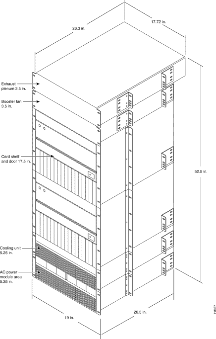
The IGX 8430 is designed for mounting in a 19-in. (48.25-cm) equipment rack. The following order of component installation is the most convenient and efficient. For some of these components, separate sections follow that contain detailed installation steps.
5. Ribbon cables for connecting upper and lower backplanes
6. Card cage tunnel around backplane ribbon cables
7. Upper cooling unit (also called booster fan unit)
The miscellaneous parts kit contains brackets for rack-mounting in either a Cisco cabinet or a user-supplied rack. The kit includes mid-mount brackets for open racks. For a Cisco cabinet, the rear-mount brackets attach to the rear vertical rail. Each of these brackets has a horizontal flange upon which the back of an individual component rests. The front of each assembly chassis has flanges that serve as front mounting brackets.
|
Caution When moving a Cisco cabinet, do not push the cabinet at its sides. Instead, grip the front or back edges. |
Step 2 To install the optional AC power supply kit, complete the steps in the "Installing the IGX 8420 or IGX 8430 AC Power Supply Assembly" section.
Step 3 To install the cooling unit, complete the steps in the section titled "Installing the Cooling Unit" section.
Step 4 Install the brackets for the card cages.
Step 5 Position the IGX card cage so the back of it faces the front of the cabinet.
|
Caution An empty card cage requires two or three people to move it. |
Step 6 With one person on each side of the card cage, lift it into the rack. In a Cisco cabinet, rest the back of the card cage on the rear-bracket flange.
When mid-mount brackets are used, screw the card cage to the brackets with #10-32 machine screws from the miscellaneous parts kit.
Step 7 Secure the front of the card cage to the front of the rack with #10-32 machine screws from the miscellaneous parts kit.
|
Caution Make sure that mounting the equipment does not create a hazardous condition because of uneven mechanical loading. The equipment rack should be securely supported. |
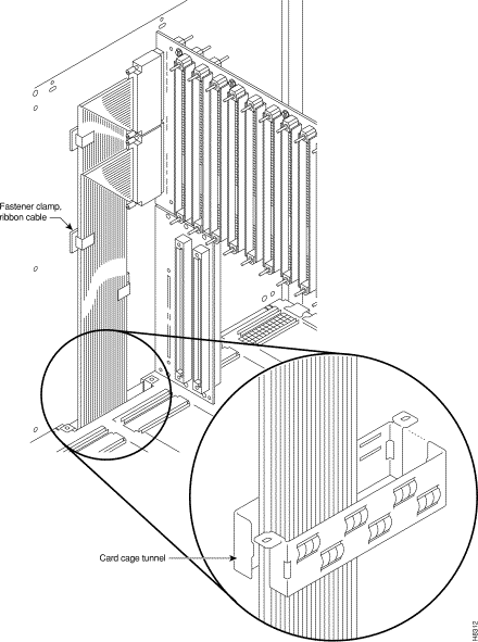
Step 8 The folded ribbon cables that connect the upper and lower backplanes pass through a cut-out space in the card cages. The cables connect to two 100-pin connectors on the front of each backplane. See Figure 2-8. If nodal processor module (NPM) cards are present, these and possibly other front cards must be removed prior to ribbon cable installation.
Connect the cable from the upper connector of the upper backplane to the upper connector in the lower backplane.
Connect the cable from the lower connector of the upper backplane to the lower connector in the lower backplane.
Step 9 A two-piece conduit called the card cage tunnel surrounds the ribbon cables and sits in the cut-out space of the card cages. Fit the pieces of the card cage tunnel around the ribbon cables and screw this unified piece into the cut-out space. Figure 2-8 shows the card cage tunnel in its normal location and prior to assembly.
Step 10 Slip the ribbon cables through the fastener clamps, then attach the fastener clamps (which include a self-adhesive base) to the side of the card cage. See Figure 2-8.
Step 11 If this is an AC-powered system, complete the procedures in the "Installing the IGX 8420 or IGX 8430 AC Power Supply Assembly" section.
Step 12 If this is a DC-powered system, go to the "DC Power Connections" section.
|
Tip To develop the most accurate IGX power budget, use Table 2-1 and Table 2-2 or the interactive power worksheets. If you decide to use the general guidelines mentioned in this section during network planning stages, confirm your results by using the power worksheets before bringing the node live in an operational environment. |
For an IGX 8410 node to use an AC power source, an AC power supply system is necessary. The
IGX 8410 power supply housing holds up to four 400-watt (W) power supplies. The AC system provides the system with -48 VDC from 100 to 240 VAC input. The AC power supply housing is between the card cage and the side wall of the node. The IGX 8410 node has one or, with AC redundancy, two AC power inputs. Figure 2-9 shows two AC inputs.
The minimum requirement for an AC-powered system is one AC source and one power supply. One supply is adequate for four cards unless you specify power supply redundancy.
Two types of redundancy exist in the AC-powered system. One redundancy is that of AC power inputs. A redundant AC power source from a building circuit that is independent of the other AC circuit provides backup if one AC circuit at the site fails. The other redundancy is that of the 400 W power supply modules. Redundancy of the 400 W power supplies provides a backup if a power supply fails.
In supporting single and dual AC inputs, power supply arrangements differ, as follows:
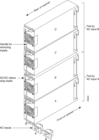
Figure 2-10 shows a dual-input system. Facing the back of a dual-input system, AC input A is on the left. AC input B in on the right. In a dual-input system, the input A supplies power supply slots A and B. Input B supplies power to slots C and D. A single AC input system does not have these distinctions: the single input receives AC power for supplies A-C. See Table 2-4 for power supply requirements.
Table 2-4 Locations of Primary and Additional Power Supplies in an IGX 8410 Node
| System | Number of Cards | N+1 Supply Redundancy | A | B | C | D |
|---|---|---|---|---|---|---|
Table 2-4 shows the minimal 400W unit requirements for different IGX 8410 configurations. The factors that determine the number of supplies are as follows:
In Table 2-4 the System column shows the number of AC inputs. The Number of Cards Column shows the number of cards at the cutoff point for more supplies. The Supply Redundancy Column indicates whether the configuration includes a redundant supply for backup. For columns A through D, an X shows that the corresponding slot in the power supply housing must have a power supply to meet the configuration requirements. The part number for a power supply is IGX8410-PS-AC.
If the IGX 8420 or IGX 8430 node uses an AC power source, proceed with this section. In a rack-mount system, the AC power supply assembly is shipped separately (as are all the other assemblies). The first assembly to install in a rack-mount system is the AC power supply assembly.
The AC power supply assembly for an IGX 8420 or IGX 8430 node consists of the following items:
Power supply installation or replacement requires the following tools:
|
Tip To develop the most accurate IGX power budget, use Table 2-1 and Table 2-2, or the interactive power worksheets. If you decide to use the general guidelines mentioned in this section during network planning stages, confirm your results by using the power worksheets before bringing the node live in an operational environment. |
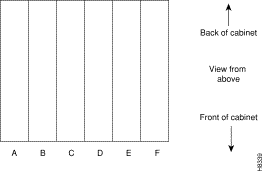
The setup for power supplies depends on the number of AC power inputs, the IGX model, and the number of cards in the system. The minimum configuration is one AC source and one supply. This minimum number applies to the IGX 8420 node with 12 or fewer cards. Figure 2-11 illustrates the alphanumeric slot designations in a full tray.
Two types of redundancy exist in the AC power supply configuration. One redundancy is that of AC power inputs. A redundant AC power source from a building circuit that is separate from the other AC circuit provides backup if one AC circuit at the site fails. The other redundancy is that of the 875 W power supply modules. Redundancy of the 875 W supplies provides a backup if one supply fails.
In supporting the two types of redundancy, power supply arrangements differ, as follows:
Table 2-5 shows the required number of power supplies for the different IGX systems. In Table 2-5, the locations for primary (or minimal) power supplies are marked with an X. The primary supplies reflect redundancy of AC inputs and backup supplies. An O indicates a slot that must have a supply, because the card cage contains more than 12 cards.
In Table 2-5, the System column lists the IGX model number coupled with the number of AC inputs and whether the single-AC input models have power supply redundancy. The table also shows the slot locations A through F and the part number of the kit that contains all the pieces for the item in the System column. Extra supplies for more than 12 cards (O) are not a part of a kit under Kit Part No. but have another part number. The part number of a supply ordered to fill extra power demands is IGX-AC-PS.
Note that, with all power supply configurations, locations for the power supplies begin at the lowest lettered slot on either side, and the occupied positions are contiguous. For example, in a dual AC system, insert a supply in A, B, D, and E.
The procedures in this section apply to both the IGX 8420 and the IGX 8430 switch in a rack. (For standalone systems, the power supplies are already installed.) To replace a power supply, follow the steps in Chapter 5, "Replacing Parts on the IGX."
Step 2 This step might require more than one person. If rear-mount brackets are used, slide in the power supply tray so that its back rests on the rear bracket.
For a mid-mount rack only, attach the tray to the mounting brackets with the head of each mounting screw on the inside of the tray and each associated nut on the outside of the bracket.
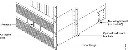
Step 3 Secure the front of the power supply tray with the front screws. When tightening each of the front screws, hold the adjacent front flange of the tray slightly to the outside so that the hinged door can freely open and close. See "Front flange" in Figure 2-12. The space between the right-angle edge of the flange and the edge of the hinged door should be approximately the width of a thumbnail.
Step 4 Install the power supplies. See Figure 2-13 for an illustration of a power supply. When a power supply almost reaches the end of the slot in the tray, a slight resistance is encountered. Push the power supply slightly farther in to achieve the final position and full connector mating.
Step 5 At the front of each supply, secure the supply to the tray by tightening the captive screw at the bottom front of the supply.
Step 6 For slots without a power supply, the hinged door has a removable, dummy panel.
Step 7 Close the hinged door and secure it with the screw at the top-center of the door. For the next step, refer to Figure 2-14, Figure 2-15, and Figure 2-16.
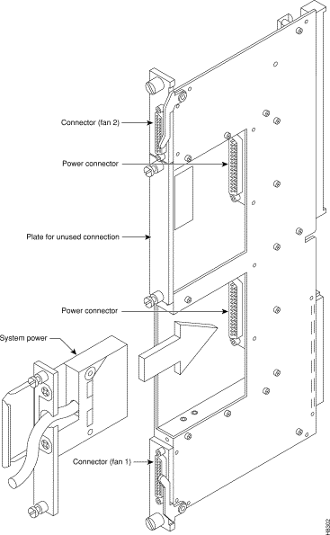
Step 8 Connect the power cables according to the applicable AC configuration shown in Figure 2-14. The cables in Figure 2-14 differ only in length; pinouts are identical. Attach cable 215982-01 from the far right connector—labeled A 1-16 in Figure 2-15—to the lower connector on the upper PE-BC. Figure 2-16 shows where system power connects to the PE-BC. It also shows the blank plate over an unused connection. If power supply trays D-F contain one or more supplies, run cable 215982-02 from the connector on the far left (B 1-16) to the upper connector on the PE-BC. See Figure 2-14 and Figure 2-15. For an IGX 8430, run cable 215982-00 from the connector labeled 17-32 to the lower connector on the lower PE-BC.
Step 9 Attach the cable guard and tighten the captive screw at its base.
Step 10 Go to the "Installing the Cooling Unit" section.
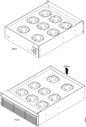
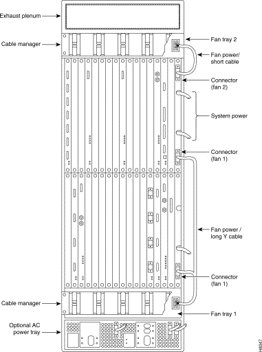
This section describes how to install the main fan tray (Fan Tray 1) in an IGX 8420 or IGX 8430 node and the upper or booster fan tray (Fan Tray 2) in an IGX 8430 node. Figure 2-17 shows the main fan tray. Figure 2-18 shows the locations of Fan Tray 1 and Fan Tray 2 in an IGX 8430 node.
Two cables exist for supplying power to the fans. The short fan power cable is used in both the IGX 8420 and the IGX 8430 nodes. The long Y cable is used in the IGX 8430 only. See Figure 2-18. In an IGX 8420, the short cable connects to connector Fan 1 of the PE-BC.
In an IGX 8430 node, the short cable goes from the Fan 2 connector of the upper PE-BC to the power connectors on Fan Tray 2. One branch of the Y cable for Fan Tray 1 is significantly longer than the other branch. The longer branch connects to the Fan 1 connector of the upper PE-BC. The shorter branch connects to the "Fan 1" connector of the lower PE-BC.
To install the cooling unit assembly:
Step 2 Slide in the cooling unit and secure it by tightening the four rack screws.
Step 3 On the PE-BCs, plug each D-connector of the appropriate fan power cable into the appropriate PE-BC connector.
Step 4 Plug the power connectors into the fan trays. At the power receptacles on each fan tray, the power connector is a latched housing. Plug P1 into connector P1. Plug P2 into connector P2. Refer to Figure 2-17.
Step 5 Attach the clamp for the fan power cord to the chassis.
Step 6 For lower fan tray installation, attach the air intake bezel.
Step 7 When power is turned on, make sure that all fans are running, and run the dsppwr command.
This section contains information on making connections to AC and DC-powered systems.
|
Caution Remember that this is a positive ground system. Ensure that polarity of the DC input wiring is correct. Under certain conditions, connections with reversed polarity might trip the primary circuit breaker and damage the equipment. |
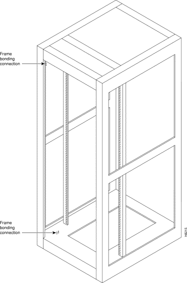
The Cisco cabinet comes with attached studs (with hardware for securing a ground conductor to the studs) at the top and bottom of the cabinet for securing the grounding conductors. These studs are 1/4 in. by 20 threads per inch. Figure 2-19 shows the Cisco cabinet with the ground attachment studs in the upper and lower parts of the cabinet.
A standalone cabinet has provisions for mounting grounding conductors on the chassis by screws. In the standalone cabinet, this provision is a pair of captive nuts (threaded holes) for the screws on the mounting rail of the chassis (1/4 in. by 20 threads per inch). Figure 2-19 shows the location of the captive nuts and screws in a standalone cabinet for securing in the ground attachments.
The attachment points in the Cisco rack and standalone cabinets for the Cisco IGX 8400 series switches are indicated by a ground symbol on the cabinet near the point of attachment.
Cisco recommends the following stacking order for attaching a ground conductor to the frame of a Cisco cabinet:
Step 2 Place the connector terminating the grounding conductor closed-loop ring or two-hole compression fitting onto the stud.
Step 3 Place another external, toothed starwasher or lockwasher onto the stud.
Step 4 Screw a nut onto the threaded stud.
Cisco recommends the following stacking order for attaching a ground conductor to the frame of a standalone enclosure:
Step 2 Place the connector terminating the grounding conductor closed-loop ring or two-hole compression fitting.
Step 3 Place another external, tooth starwasher or lockwasher.
Step 4 Screw the entire assembly into the captive nut in the mounting rail beneath the cover plate. See Figure 2-20 for an illustration of this stacking order in an IGX 8420 node. Figure 2-21 shows the location of the frame bonding connection on an IGX 8410 node.
Cisco provides at least one, 8-ft (3-m) power cord with each AC power supply assembly. To make AC power connections to the IGX:
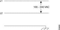
Step 2 Make sure that the AC plug wiring has the correct relationship. Figure 2-22 shows the voltage across the wires in an IGX 8410 plug. Figure 2-25 shows the voltage across the wires in an IGX 8420 or IGX 8430 plug.
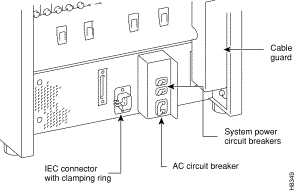
Step 3 Plug the power cord into the IEC connector and tighten the screw on the clamping ring. See Figure 2-23 for an example of the IGX 8410 AC power area, Figure 2-24 for the IGX 8420 AC power area, and Figure 2-25 for information on IGX 8420 or IGX 8430 AC connection wiring.
Step 4 Plug the AC power cord into a single-phase wall outlet rated for a nominal voltage.
For an IGX 8410 node, the AC voltage should be from 200 to 240 VAC or 100 to
120 VAC. The outlet must also be capable of supplying up to 12 amperes (A) (13 A in the UK). The building circuit should be protected with a 15 A or 20 A circuit breaker.
For an IGX 8420 or 8430, the AC voltage should be between 200 and 240 VAC. Each outlet must also be capable of supplying up to 16 A (13 A in the UK, where the plug has a built-in, 13 A fuse). In North America, the building circuit should be protected with a 20 A circuit breaker.
Step 5 For the dual power feed version, plug each power cord into a receptacle that connects to a separate building circuit to provide backup if one building circuit fails. Each building circuit should have a 15 A or 20 A circuit breaker.
Step 6 The ground (green) wire of the AC power cord is connected to the IGX for safety ground. Make sure that each AC receptacle in the building is grounded.
Step 7 In addition to the preceding, Cisco recommends that you provide an AC power strip with at least four outlets. Place the strip near the IGX to supply optional modems, CSUs, DSUs, or test equipment. Be sure to connect this power strip to an AC source voltage that is standard for the region (for example, 115 VAC in North America or 230 VAC in Europe).
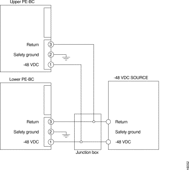
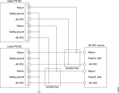
A system that uses a DC power source has one or two configurations, as follows:
Wiring is connected from one or two -48-VDC power sources to one or two DC PEMs per shelf. Cisco does not provide the wire between the node and the source. Instead, the installer or customer must supply it. These wires should be capable of carrying 20 A. The diagrams on the pages that follow show DC wiring for single and redundant DC sources for all IGX models.
|
Tip The single-shelf IGX 8410 and IGX 8420 have a total primary power limitation of 1050 W. The dual-shelf IGX 8430 has a total primary power limitation of 2100 W. Primary power consumption cannot exceed these limitations. Consult the power worksheets (see the "Power Worksheets" section) to verify that your power configuration is within budget. |
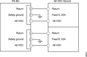
As the detailed steps on the following pages explain, installing DC power consists of attaching the three wires of the DC power source to a removable wiring block, then plugging that block into the connector on the PEM. The PEM is plugged into the PE-BC. Figure 2-30 is a view of a PE-BC (out of the card cage) with the PEM wired up and plugged into the PE-BC. Figure 2-30 shows a nonredundant DC power configuration. Note the blank plate that covers the unused connection.
|
Note A DC-powered system makes no distinction between a primary and redundant PEM (unlike the redundancy scheme in an AC-powered system). However, Cisco suggests putting a label of some type on the PEM to identify the branch circuit to which it goes. |
To make a DC power connection:
Step 2 Insert and secure the stripped ends of the wire in the wiring block according to the scheme in Figure 2-31 and Figure 2-32 . Figure 2-31 illustrates the polarity of each connection on the pluggable terminal block. The numbers start with 1 at the bottom and go to 3. The connection at the bottom is for the -48 VDC wire. The middle wire is the safety ground. The connection at the top is for the positive return wire (for the -48 VDC). Figure 2-32 shows the assembly with an example wire and the screw that secures it in the pluggable wire block.
Step 3 Attach the pluggable terminal block to the receptacle on the PEM.
Step 4 Loop the DC wiring through the strain relief clamp.
Step 5 Connect the DC input wiring to a DC source capable of supplying at least 20 A (typical). The -48 VDC power source in the building should have a 25-A DC circuit breaker. The building's wiring should include an easily accessible disconnect device. Make sure that the ground wire connects to a reliable building (earth) ground.
Step 6 Leave the cable guard off until power is on.
Step 7 Before you turn on the system power, check the supply voltage. Use the screws at positions 1 and 3 on the pluggable terminal block as a convenient measuring point. Also, check the impedance between the safety ground (screw at location 2 on the pluggable terminal block) and the chassis. It should be close to 0.
Step 8 Turn on the power, and check the voltage at the screws at positions 1 and 3 on the pluggable terminal block.
Step 9 Turn off the power, and go to "Installing the IGX."
|
Note In slots where no back card exists, a blank faceplate must reside to block electromagnetic interference (EMI) and radio frequency interference (RFI) and to ensure correct air flow. |
For introduction on installing the IGX, see "Preparing the Cards."
For software configuration and service provisioning information, see the Cisco IGX 8400 Series Provisioning Guide, Chapter 1, "Introduction to the Cisco IGX 8400 Series."
For more information on switch software commands, refer to the Cisco WAN Switching Command Reference, Chapter 1, "Command Line Fundamentals ."
|
Tip |
![]()
![]()
![]()
![]()
![]()
![]()
![]()
![]()
Posted: Thu May 22 06:04:52 PDT 2003
All contents are Copyright © 1992--2003 Cisco Systems, Inc. All rights reserved.
Important Notices and Privacy Statement.