|
|

Table Of Contents
Enclosure and Power Installation
Telecommunications Requirements
Seismic Anchoring for the Cisco Closed Rack
IGX 8410 Enclosure Installation
Stand-Alone System Installation
IGX 8420/8430 Enclosure Installation
Stand-Alone System Installation
IGX 8420 Rack Mount Installation
IGX 8430 Rack-Mount Installation
Installing the IGX 8420/8430 AC Power Supply Assembly
Making Power and Ground Connections
Making the Frame Bonding (Ground) Connection
Enclosure and Power Installation
Parts Checklist
Before you install the system, verify that all of the required parts are present and in good condition. If anything is missing or damaged, contact your sales representative.
IGX 8410 Enclosure
Check the cabinet for the following inventory:
•
For rack-mount systems, four permanent mounting brackets are present. Also, for installation purposes only, a pair of temporary mounting brackets and a temporary spacer bracket are present.
•
IGX 8420/8430 Enclosures
Check the cabinet for the following inventory:
•
•
Plug-In Cards
Make sure all purchased cards are present. Check the number and type of cards shipped against the number and type of card purchased. In the following list, the column on the left lists the front cards. The column on the right lists the possible corresponding back cards. Check off each card type as you inventory them.
An inventory list of the installed cards is shipped with the unit. The list includes each card's serial number, revision number, and slot number (serial and revision numbers are also found on the solder side of each card). Check for the presence of any other items on the shipping list. After verifying that the correct cards are present, tape a copy of the inventory list to the back of this manual.
Site Preparation
The site must satisfy the following requirements:
•
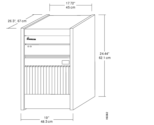
The standalone IGX 8410 node requires a floor area 19.9 inches (50.5 cm) wide and at least
47 inches (180 cm.) deep. This depth allows for opening the front door. Sufficient clearance around the cabinet must also be provided for access to the front and back of the cabinet while the door is open. The rack-mount IGX 8410 node requires 24.44 inches of vertical space.A standalone IGX 8420 or 8430 node requires a floor area 19.9 inches (50.5 cm) wide and at least 47 inches (119.4 cm) deep. This spacing lets you open the front door. Clearance around the cabinet must also allow access to the front and back of the cabinet while the door is open. The rack-mount IGX 16 requires 32 inches (81.3 cm) of vertical space. The rack-mount IGX 8430 node requires 55 inches (139.7 cm) of vertical space.
In a rack-mount system, the mounting rail pattern follows the EIA standard of 56 inches (or
32 rack-mount units). For displacement information for the IGX components and other components in the Cisco cabinet, refer to the appendix titled " ".•
The IGX operating environment should be as follows:
Temperature and humidity range: 0
Ήto 40ΉC (32Ήto 104ΉF) for normal operation, 50ΉC for up to 72 hours. Up to 85% relative humidity, non-condensing.Shock: the switch withstands 10 G, 10 ms. at 1/2 sine wave.
Vibration: the switch withstands 1/4 G, 20 to 500 Hz.
•
For AC power use, an AC power source must be available within 6 feet (1.8 m) of the IGX node. For systems using a DC source, Cisco does not supply the DC power cord, so the user or installer determines the cord length and the distance to the DC source. The wire should be 10-12 AWG or 4 square millimeters.
•
A fully loaded, AC-powered IGX 8410 node dissipates up to 3,500 BTUs (1 KW hour). A DC-powered IGX 8410 node can dissipate up to 2720 BTUs.
A fully loaded, AC-powered IGX 8420 node dissipates up to 4300 BTUs (1 KW hour). A DC-powered IGX 8420 can dissipate up to 3600 BTUs.
A fully loaded, AC-powered IGX 8430 node dissipates up to 8600 BTUs (1 KW hour). A DC-powered IGX 8430 node can dissipate up to 6800 BTUs.
•
A fully loaded IGX 8410 enclosure can weigh up to 173 lbs (79 Kgs). A fully loaded IGX 8420 enclosure can weigh up to 250 lbs (112.5 Kgs). A fully loaded IGX 8430 enclosure can weigh up to 500 lbs (225 Kgs).
CautionIf you move a Cisco-supplied cabinet, do not push it at its sides. Push at the front or back.
•
Raised flooring with sufficient under-floor space to house the cables is recommended.
•
An IGX node is either mounted in a rack or free-standing (in a stand-alone cabinet). The location of the IGX node should accommodate the routing of the data cables and the termination of the telephone company's or common carrier's circuits.
•
The IGX 8410 node has one mounted wrist strap at the front and one at the back of the cabinet. Personnel with access to the IGX 8410 cards should put on a wrist strap before handling the cards. An IGX 8420/8430 node does not come with an attached wrist strap.
Seismic Considerations
To provide some protection against seismic activity, the feet and wheels of the IGX stand-alone cabinets can be removed to permit the cabinet to be bolted to a concrete floor or to a structural member in the floor.
In Cisco-supplied cabinets, provisions are available for seismic anchoring. Holes exist in the upper and lower corners for 3/8" or 1/2" bolts. Also, an optional stability plate can be purchased with the Cisco cabinet. The stability plate is bolted to the floor, then the Cisco cabinet is bolted to the stability plate. The " Seismic Anchoring for the Cisco Closed Rack" section contains instructions for installing the seismic stability plate.
Safety Requirements
The following paragraphs contain general safety information and information on telecommunications safety requirements.
General Requirements
Warning
The following safety requirements must be observed:
•
•
•
•
Power and Grounding
This section lists the requirements that relate to electrical power and grounding. These requirements cover installations at Central Office (CO) and Private Enterprise locations.
AC Power Circuit Breakers
For an AC-powered system, verify that the node's power comes from a dedicated AC branch circuit. The circuit must be protected by a dedicated, two-pole circuit breaker. The circuit breaker must have a rated current and trip delay that is greater than those of the IGX circuit breaker. Cisco Systems recommends the following:
•
•
The IGX 8420 and IGX 8430 nodes use a 20A, 2-pole circuit breaker for each AC input. The manufacturer of this circuit breaker is ETA, and the ETA part number for the circuit breaker is 8340-F120-P1P2-B2H020A. The IGX 8410 node uses a 15A, 2-pole AC circuit breaker on each input. This circuit breaker comes from either ETA (part number 8340-F120-P1P2-B2H015A) or Airpax (part number IEGH11-1-62-15.0-91V).
DC Power Circuit Breakers
For a DC-powered system, verify that the node's power comes from a dedicated DC branch circuit. The circuit must be protected by a dedicated circuit breaker. The circuit breaker must have a rated current and trip delay that is greater than those of the IGX circuit breaker. Cisco Systems recommends the site have a dedicated 25A, 1-pole circuit breaker with a medium trip delay at each branch circuit.
The DC-powered nodes use a 25A, 1-pole circuit breaker with a short trip delay on each -48V input. The manufacturer of this circuit breaker is ETA, and the ETA part number is 8340F110P1K1A2H00025.
Electrical Power for AC Units
An AC power source must be available within 6 feet (1.8 m) of the system and easily accessible. Before turning on the power, verify that the power supplied to the node comes from a dedicated branch circuit.
The power receptacles to which the node connects must be of the grounding type. The grounding conductors that connect to the receptacles should connect to protective earth at the service equipment.
Electrical Power for DC Units
Only an 48 VDC supply that complies with the Safety Extra Low Voltage (SELV) requirements of EN 60950 can connect to the IGX DC input.
For DC supply connections, consult local and/or national codes for proper conductor sizing. The conductors must be suitable for 20 Amps. Wiring that is 10 to 12 AWG (4 sq. mm) is adequate.
Bonding and Grounding
To maintain the full EMI and EMC integrity of this equipment, it must be bonded to an Integrated Ground Plane or an Isolated Ground Plane network. The purpose of this is to mitigate the damaging effects to equipment from Electrostatic Discharge and Lightning. Refer to the latest edition of ITU Recommendation K.27 or Bellcore GR-1089-CORE requirements to ensure that the correct Bonding and Grounding procedures are followed. As recommended in these documents, a frame bonding connection is provided on the Cisco-supplied cabinet for rack-mounted systems and on the stand-alone cabinets.
Refer to " Making the Frame Bonding (Ground) Connection" later in this chapter for information on the locations of the frame bonding connections and how to make a connection.
Except for the AC power supply module, every module in a rack-mount system relies on the rack itself for grounding. Therefore, the rack must be properly connected to protective earth before operating the system.
A DC-powered IGX node must have grounding conductors that connect at two separate locations, as follows:
•
•
Telecommunications Requirements
The telecommunications requirements might be relevant to a private network connected to the public, switched networks in some international service areas.
•
— BC-E1 ports (G.703 2048 Kbits per second).— SDI-EIA/TIA-232, LDI-EIA/TIA-232, BC-SR, SDI-EIA/TIA-449, FRI-V.35 (approved for direct connection to V.35 leased digital circuit).— SDI-EIA/TIA-449 (when connected via Cisco EIA/TIA449/X.21 interface cable).•
— BC-E1 ports (G.703 2048 Kbps, when connected to a CVM or NTM front card).
Note
FCC Requirements
The following tables represent the legal minimum immunity requirements for ITE products to be sold into Europe after August 2001.
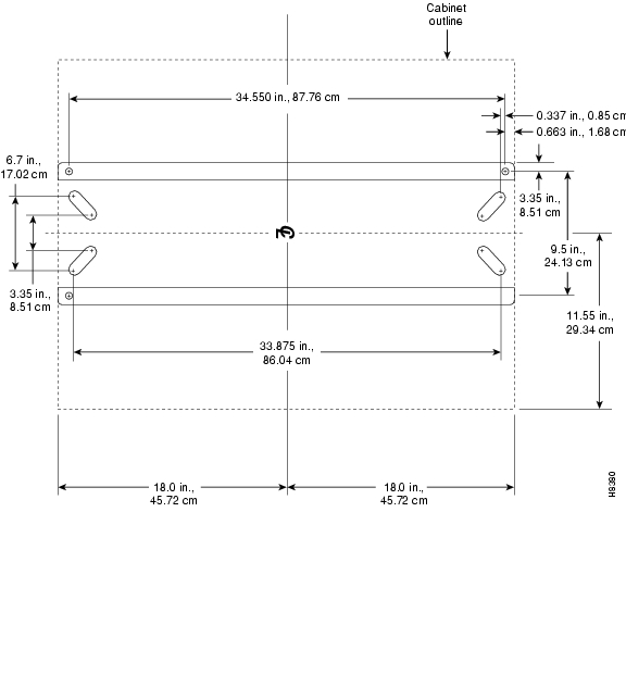
Seismic Anchoring for the Cisco Closed Rack
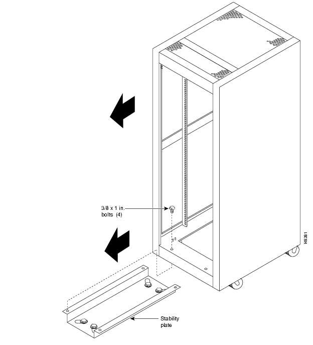
This section describes installing the Cisco-supplied cabinet with the optional stability plate for seismic anchoring. If the stability plate is not present, go to the applicable section that describes how to set up an enclosure. The sections immediately follow and are titled " IGX 8410 Enclosure Installation" and " IGX 8420/8430 Enclosure Installation."
To set up the Cisco cabinet with the stability plate:
Step 1
Step 2
Step 3
Step 4
Step 5
Figure 2-1 Stability Plate Dimensions
Figure 2-2 Installing a Cisco-Supplied Rack Over the Stability Plate
IGX 8410 Enclosure Installation
Installing an IGX 8410 switch requires the following tools and equipment:
•
•
•
•
•
•
Stand-Alone System Installation
The installation steps consist of placing the stand-alone IGX 8410 node at its operating location, unpacking it, and verifying the integrity of the enclosure and power connections. Note that the cabinet is 19.9" wide.
After the system is at its operational location, follow the steps for connecting power. If the system has an AC power source, go to " AC Power Connections" section. If the system has a DC power source, go to the " DC Power Connections" section.
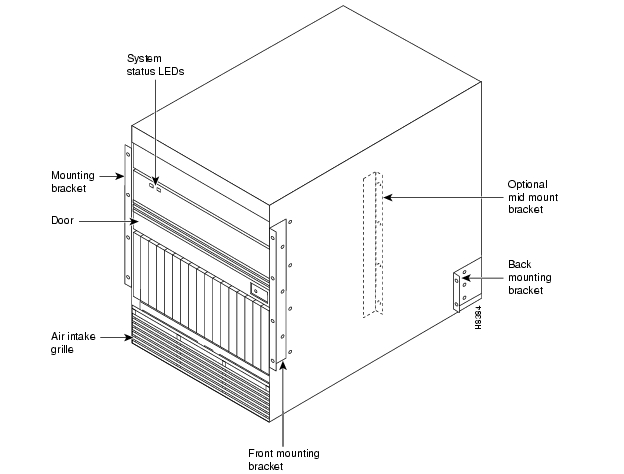
Rack-Mount Installation
The rack-mount IGX 8410 node fits in a 19 inch (48.25 cm.) rack with a minimum of 17.75 inches between rails. For mounting the chassis in a rack, brackets are attached to the front of the chassis. A pair of mounting brackets are attached at the back of the chassis after it is placed in the rack. Brackets for a mid-rack mounting also come with the kit.
To support the weight of the IGX 8410 node during installation, Cisco includes two temporary spacer brackets and a temporary mounting bracket. You remove these pieces after installation. The spacer brackets stabilizes the rack. Also, the temporary mounting bracket together with the spacer brackets creates a partial shelf onto which you can slide the node. These pieces support the system while you secure the permanent front and back mounting brackets to the rack.
CautionIf an IGX node is mounted in a cabinet, be sure an unrestricted air flow is available in and out of the enclosure.
To install an IGX 8410 node in a rack:
Step 1
Step 2
Figure 2-3 IGX 8410 Rack Mounting Dimensions
CautionIf you must move a Cisco cabinet to install an IGX switch, do not push the cabinet at its sides. Instead, grip the cabinet at the front or back edges to maneuver it to the setup location.
Step 3
Step 4
Figure 2-4 Temporary Spacer Bracket and Mounting Bracket
Step 5
CautionAn IGX 8410 node requires a 2 or 3-person lift to put it in the rack.
Step 6
Step 7
Figure 2-5 Rack-Mount Cabinet
CautionMake sure that mounting the equipment does not create a hazardous condition due to uneven mechanical loading. The equipment rack should be securely supported.
Step 8
Step 9
Step 10
Step 11
IGX 8420/8430 Enclosure Installation
Installing an IGX 8420 or IGX 8430 node requires the following tools and equipment:
•
•
•
•
•
•
Rack-mount systems come with the parts described in the assembly instructions.
Stand-Alone System Installation
Because Cisco stand-alone systems come with all components installed in the cabinet, the installation steps consist of placing the unit at its operational location, unpacking it, and verifying the structural and power connection integrity before turning on the power. Note that a stand-alone cabinet is 19.9" wide. The adjustable levelers require a 5/8" wrench. If the system has an AC power source, go to the " AC Power Connections"section. If the system has a DC power source, go to the " DC Power Connections" section.
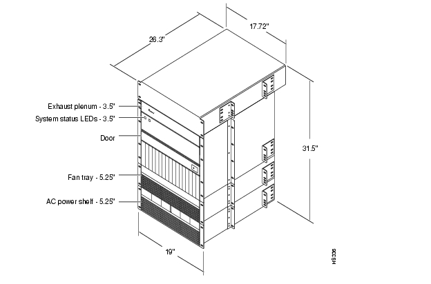
IGX 8420 Rack Mount Installation
The rack-mount IGX 8420 node fits in a 19 inch (48.25 cm.) rack. The front of each assembly has flanges that serve as the front mounting brackets. The assembly kit contains other brackets for different mounting setups. The following order of component installation is the most convenient and efficient. For some of these components, separate sections follow with detailed installation steps.
1
2
3
4
Note that the vertical spacing between components, such as the card cage and fan tray, must be in the range .047"-.077" (0.119 cm-0.196 cm).
The miscellaneous parts kit for rack systems contains brackets for both a Cisco-supplied cabinet and a user-supplied rack. The kit includes mid-mount brackets for open racks.
The rear-mount brackets attach to the rear vertical rail in a Cisco-supplied cabinet. Each of these brackets has a horizontal flange upon which the back of each IGX component rests. The front of each assembly chassis has flanges that serve as the front mounting brackets.
CautionIf an IGX node is mounted in a user-supplied cabinet, be sure air can flow unrestricted in and out of the cabinet. For assistance, contact the TAC through Cisco Customer Engineering.
To install the IGX node in a rack:
Step 1
CautionWhen moving a Cisco-supplied cabinet, do not push the cabinet at its sides. Instead, grip its front or back edges.
Step 2
Step 3
Step 4
CautionAn empty IGX card cage requires a 2 or 3-person lift to move into place.
Figure 2-6 IGX 8420 Rack Mounting Dimensions
Step 5
Step 6
Step 7
CautionMake sure that mounting the equipment does not create a hazardous condition due to uneven mechanical loading. The equipment rack should be securely supported.
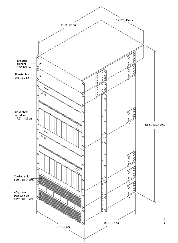
IGX 8430 Rack-Mount Installation
The IGX 8430 is designed for mounting in a 19 inch (48.25 cm.) equipment rack. The following order of component installation is the most convenient and efficient. For some of these components, separate sections follow that contain detailed installation steps.
1
2
3
4
5
6
7
8
The miscellaneous parts kit contains brackets for rack-mounting in either a Cisco-supplied cabinet or a user-supplied rack. The kit includes mid-mount brackets for open racks. For a Cisco-supplied cabinet, the rear-mount brackets attach to the rear vertical rail. Each of these brackets has a horizontal flange upon which the back of an individual component rests. The front of each assembly chassis has flanges that serve as front mounting brackets.
CautionIf an IGX node goes in a user-supplied cabinet, be sure air can freely flow in and out of the enclosure. Note also that the vertical spacing between components, such as the card cage and fan tray, must be in the range .047"-.077" (0.119 cm-0.196 cm).
CautionWhen moving a Cisco-supplied cabinet, do not push the cabinet at its sides. Instead, grip the front or back edges.
Step 1
Step 2
Step 3
Step 4
Step 5
Figure 2-7 IGX 8430 Rack Mounting Dimensions
CautionAn empty card cage requires a 2 or 3-person lift to move.
Step 6
When mid-mount brackets are used, screw the card cage to the brackets with #10-32 machine screws from the miscellaneous parts kit.
Step 7
CautionMake sure that mounting the equipment does not create a hazardous condition due to uneven mechanical loading. The equipment rack should be securely supported.
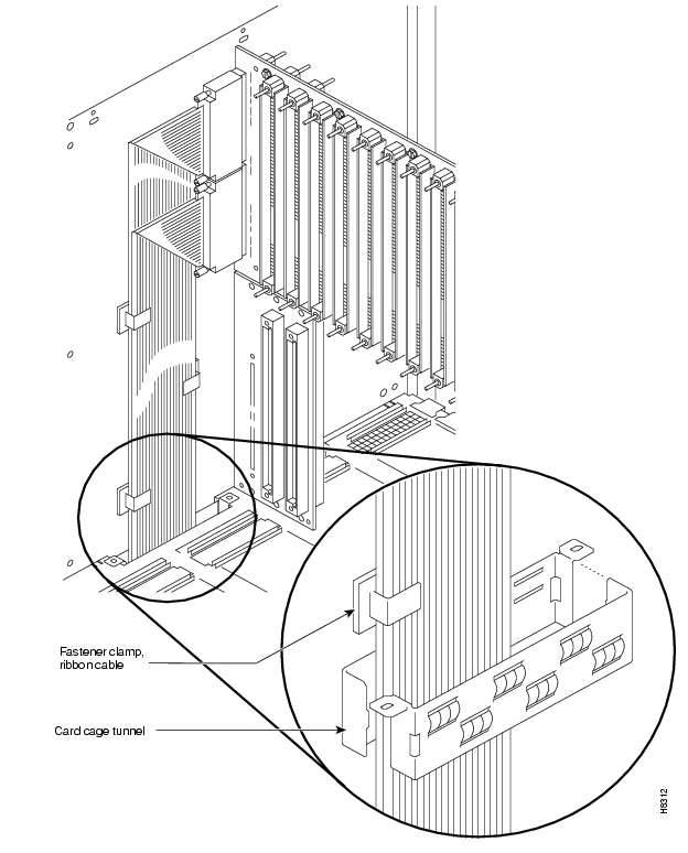
Step 8
Connect the cable from the upper connector of the upper backplane to the upper connector in the lower backplane.
Connect the cable from the lower connector of the upper backplane to the lower connector in the lower backplane.
Step 9
Step 10
Step 11
Step 12
Figure 2-8 IGX 8430 Backplane Connector Cables
Installing AC Power
Two sections on AC power module installation follow. The immediately following sections describe AC power module installation for the IGX 8410 node, then the sections on the IGX 8420/8430 node follow.
AC Power in the IGX 8410 Node
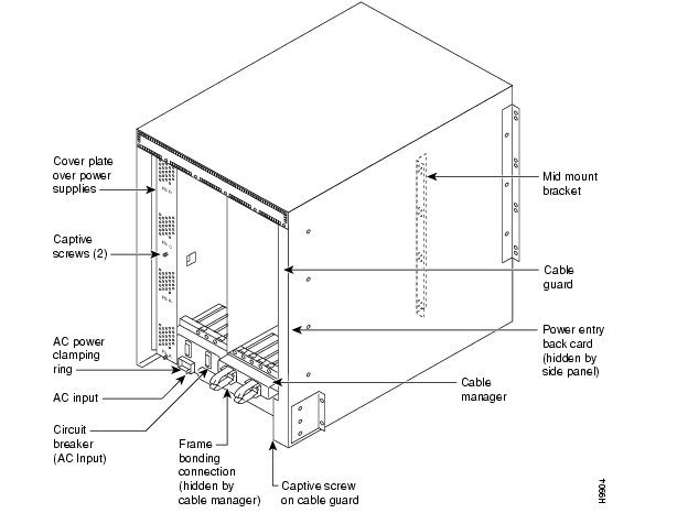
For an IGX 8410 node to use an AC power source, an AC power supply system is necessary. The IGX 8410 power supply housing holds up to four, 400-Watt power supplies. The AC system provides the system with -48 VDC from 100 to 240 VAC input. The AC power supply housing is between the card cage and the side wall of the node. The IGX 8410 node has one or, with AC redundancy, two AC power inputs.
Two types of redundancy exist: power source redundancy, in case one AC circuit fails, and AC power supply redundancy, in case a supply fails. shows two AC inputs.
Figure 2-9 IGX 8410 Power Supply Area Back View, AC System
The minimum requirement for an AC-powered system is one AC source and one power supply. One supply is adequate for four cards unless you specify power supply redundancy. See for power supply requirements. shows the power supply slot designations and exterior.
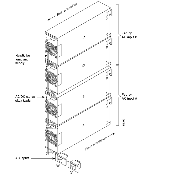
shows a dual-input system. Facing the back of a dual-input system, AC Input A is on the left. AC Input B in on the right. In a dual-input system, the Input A supplies power supply slots A and B. Input B supplies power to slots C and D. A single AC input system does not have these distinctions: the single input receives AC power for supplies A-C.
Figure 2-10 Power Supply Slot Designations, Dual AC System
Two types of redundancy exist in the AC-powered system. One redundancy is that of AC power inputs. A redundant AC power source from a building circuit that is independent of the other AC circuit provides backup if one AC circuit at the site fails. The other redundancy is that of the 400-Watt power supply modules. Redundancy of the 400-Watt power supplies provides a backup if a power supply fails.
In supporting single and dual AC inputs, power supply arrangements differ, as follows:
•
•
shows the minimal 400-Watt unit requirements for different IGX 8410 configurations. The factors that determine the number of supplies are as follows:
•
•
•
In the System column shows the number of AC inputs. The Number of Cards column shows the number of cards at the cutoff point for more supplies. The Supply Redundancy column indicates whether the configuration includes a redundant supply for backup. For columns A through D, an X shows that the corresponding slot in the power supply housing must have a power supply to meet the configuration requirements. The part number for a power supply is IGX8410-PS-AC.
Table 2-2 Locations of Primary and Additional Supplies in an IGX 8410 Node
1 AC Input
4 or less
No
X
4 or less
Yes
X
X
more than 4
No
X
X
more than 4
Yes
X
X
X
2 AC inputs
4 or less
X
X
more than 4
X
X
X
X
Installing the IGX 8420/8430 AC Power Supply Assembly
If the IGX 8420 or IGX 8430 node uses an AC power source, proceed with this section. In a rack-mount system, the AC Power Supply Assembly is shipped separately (as are all the other assemblies). The first assembly to install in a rack-mount system is the AC power supply assembly.
The AC power supply assembly for an IGX 8420 or IGX 8430 node consists of the following items:
•
•
•
•
•
•
Power supply installation or replacement requires the following tools:
•
•
Understanding the AC Power Supply Configuration
The setup for power supplies depends on the number of AC power inputs, the IGX model, and the number of cards in the system. The minimum configuration is one AC source and one supply. This minimum number applies to the IGX 8420 node: with 12 or fewer cards, one supply is enough. illustrates the alphanumeric slot designations in a full tray. The paragraphs that follow refer to these designations.
Figure 2-11 Power Supply Slot Designations
Redundancy
Two types of redundancy exist in the AC power supply configuration. One redundancy is that of AC power inputs. A redundant AC power source from a building circuit that is separate from the other AC circuit provides backup if one AC circuit at the site fails. The other redundancy is that of the 875-Watt power supply modules. Redundancy of the 875-Watt supplies provides a backup if one supply fails.
In supporting the two types of redundancy, power supply arrangements differ, as follows:
•
•
Power Supply Quantities
shows the required number of power supplies for the different IGX systems. In , the locations for primary (or minimal) power supplies are marked with an X. The primary supplies reflect redundancy of AC inputs and backup supplies. An O indicates a slot that must have a supply because the card cage contains more than 12 cards.
In , the System column lists the IGX model number coupled with the number of AC inputs and whether the single-AC input models have power supply redundancy. The table also shows the slot locations A through F and the part number of the kit that contains all the pieces for the item in the System column. Extra supplies for more than 12 cards (O) are not a part of a kit under Kit Part No. but have another part number. The part number of a supply ordered to fill extra power demands is IGX-AC-PS.
Table 2-3 Locations of Primary and Additional Supplies in an IGX 8420/8430 Node
Note that, with all power supply configurations, locations for the power supplies begin at the lowest lettered slot on either side, and the occupied positions are contiguous. For example, in a dual AC system, insert a supply in A, B, D, and E.
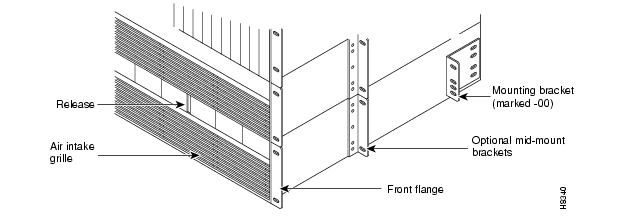
AC Installation in a Rack-Mount Cabinet
The procedures in this section apply to both the IGX 8420 and the IGX 8430 switch in a rack. (For stand-alone systems, the power supplies are already installed.) To replace a power supply, follow the steps in the chapter titled "Repair and Replacement."
Step 1
Figure 2-12 Front of Rack Mount System
Step 2
For a mid-mount rack only, attach the tray to the mounting brackets with the head of each mounting screw on the inside of the tray and each associated nut on the outside of the bracket.Step 3
Step 4
Step 5
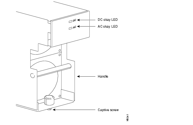
Figure 2-13 Power Supply (Viewed From Front and Left)
Step 6
Step 7
Step 8
Step 9
Step 10
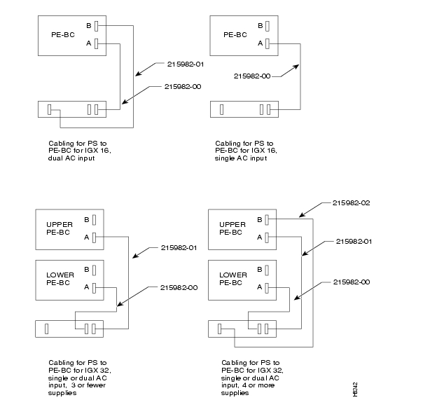
Figure 2-14 Wire Diagrams for Different Power Configurations
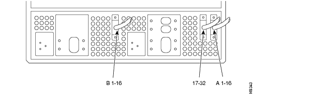
Figure 2-15 AC Power Supply Shelf Back View
Figure 2-16 Inserting System Power Connector to E-Card, AC-Powered System
Installing the Cooling Unit
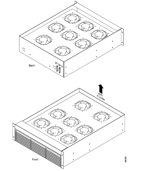
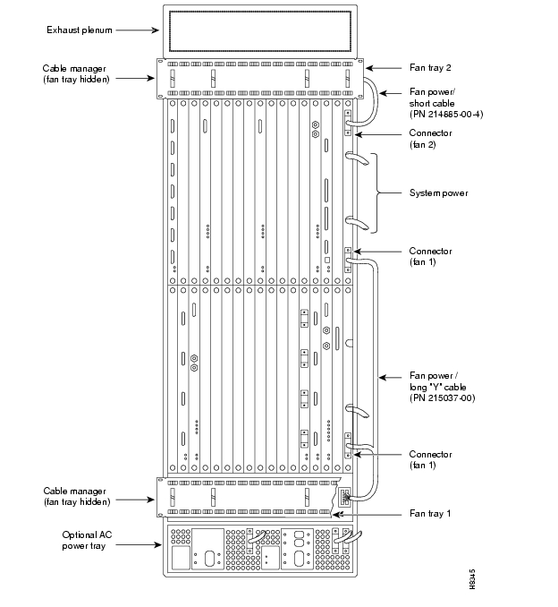
This section describes how to install the main fan tray (Fan Tray 1) in an IGX 8420/8430 node and the upper or booster fan tray (Fan Tray 2) in an IGX 8430 node. shows the main fan tray. shows the locations of Fan Tray 1 and Fan Tray 2 in an IGX 8430 node.
Figure 2-17 Fan Tray Assembly
Two cables exist for supplying power to the fans. The short fan power cable is used in both the IGX 8420 and the IGX 8430 nodes. The long "Y" cable is used in the IGX 8430 only. See . In an IGX 8420, the short cable connects to connector "Fan 1" of the PE-BC.
In an IGX 8430 node, the short cable goes from the "Fan 2" connector of the upper PE-BC to the power connectors on Fan Tray 2. One branch of the Y cable for Fan Tray 1 is significantly longer than the other branch. The longer branch connects to the "Fan 1" connector of the upper PE-BC. The shorter branch connects to the "Fan 1" connector of the lower PE-BC.
To install the cooling unit assembly:
Step 1
Step 2
Step 3
Step 4
Step 5
Step 6
Step 7
Figure 2-18 IGX 8430 Back View
Making Power and Ground Connections
This section contains information on making connections to AC and DC-powered systems.
CautionRemember that this is a positive ground system. Ensure that polarity of the DC input wiring is correct. Under certain conditions, connections with reversed polarity might trip the primary circuit breaker and/or damage the equipment.
Warning
Before connecting power, make sure all IGX circuit breakers are off.
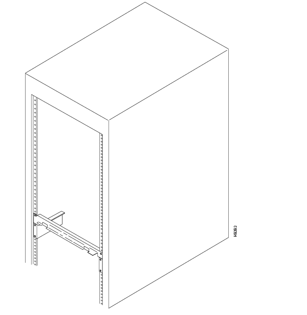
Making the Frame Bonding (Ground) Connection
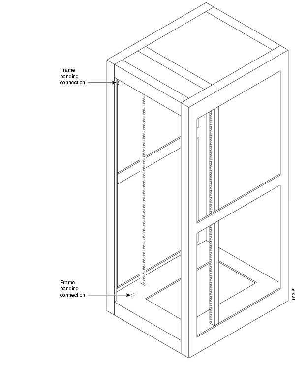
The Cisco-supplied cabinet comes with attached studs (with hardware for securing a ground conductor to the studs) at the top and bottom of the cabinet for securing the grounding conductors. These studs a 1/4" by 20 threads per inch. shows the Cisco cabinet with the ground attachment studs in the upper and lower parts of the cabinet.
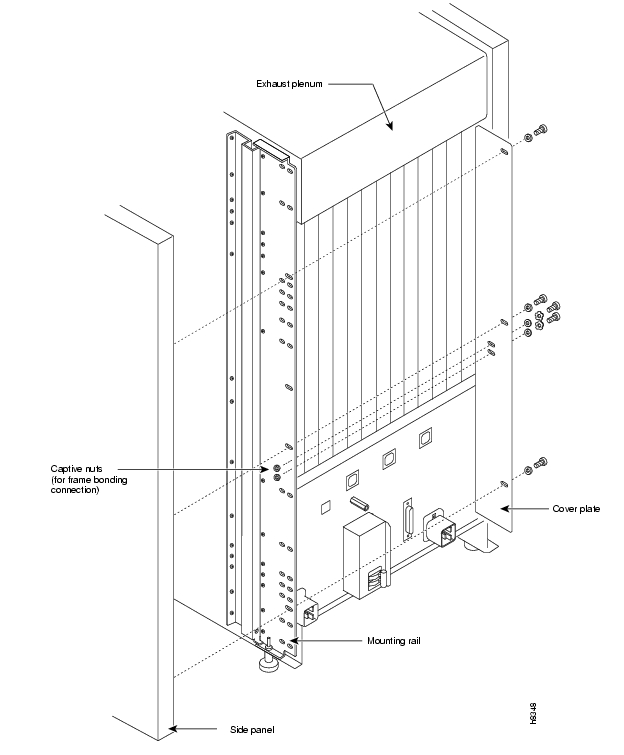
A stand-alone cabinet has provisions for mounting grounding conductors on the chassis by screws. In the stand-alone cabinet, this provision is a pair of captive nuts (threaded holes) for the screws on the mounting rail of the chassis (1/4" by 20 threads per inch). shows the location of the captive nuts and screws in a stand-alone cabinet for securing in the ground attachments.
The attachment points in the Cisco-supplied rack and stand-alone cabinets for the Cisco IGX 8400 series switches are indicated by a ground symbol on the cabinet near the point of attachment.
Cisco Cabinet Connections
Cisco recommends the following stacking order for attaching a ground conductor to the frame of a Cisco-supplied cabinet:
Step 1
Step 2
Step 3
Step 4
Stand-Alone Cabinet Connections
Cisco recommends the following stacking order for attaching a ground conductor to the frame of a standalone enclosure:
Step 1
Step 2
Step 3
Step 4
Figure 2-19 Frame Bonding Connection in Cisco-Supplied Rack
Figure 2-20 Frame Bonding Connections in IGX 8420 Standalone Switch
Figure 2-21 IGX 8410 Frame Bonding Connections
AC Power Connections
Cisco provides at least one, eight-foot (three meter) power cord with each AC Power Supply Assembly. To make AC power connections to the IGX:
Step 1
Step 2
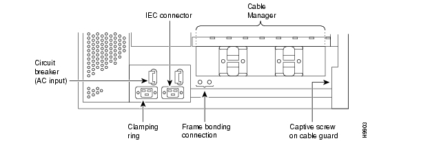
Figure 2-22 IGX 8410 AC Connection Wiring
Step 3
Figure 2-23 IGX 8410 Circuit Breakers
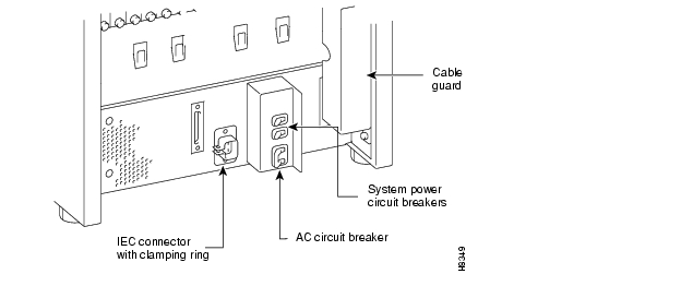
Figure 2-24 IGX 8420/8430 AC Connection Wiring
Figure 2-25 IGX 8420 Circuit Breakers
Step 4
For an IGX 8410 node, the AC voltage should be between 200 to 240 VAC or 100 to
120 VAC. The outlet must also be capable of supplying up to 12 Amps (13 Amps in the UK). The building circuit should be protected with a 15 or 20 Amp circuit breaker.For an IGX 8420 or 8430, the AC voltage should be between 200 and 240 VAC. Each outlet must also be capable of supplying up to 16 Amps (13 Amps in the UK, where the plug has a built-in, 13 Amp fuse). In North America, the building circuit should be protected with a 20 Amp circuit breaker.
Step 5
Step 6
Step 7
Note
DC Power Connections
A system that uses a DC power source have one or two configurations, as follows:
•
— Single power source— Dual power source (a separate branch circuit supplies each source)•
— Single power source— Dual power source (a separate branch circuit supplies each source)•
— Single power source for each shelf— Dual power source for each shelf (a separate branch circuit supplies each source)Wiring is connected from one or two -48 VDC power sources to one or two DC PEMs per shelf. Cisco does not provide the wire between the node and the source. Instead, the installer or customer must supply it. These wires should be capable of carrying 20 Amps. The diagrams on the pages that follow show DC wiring for single and redundant DC sources for all IGX models.
•
•
•
•
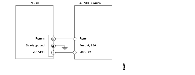
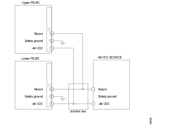
Figure 2-26 Single Shelf With Single DC Source
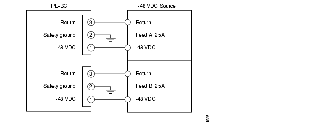
Figure 2-27 Single Shelf With Dual DC Sources
Figure 2-28 IGX 8430 With a Single DC Source
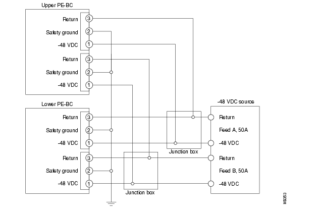
Figure 2-29 IGX 8430 With Redundant DC Sources
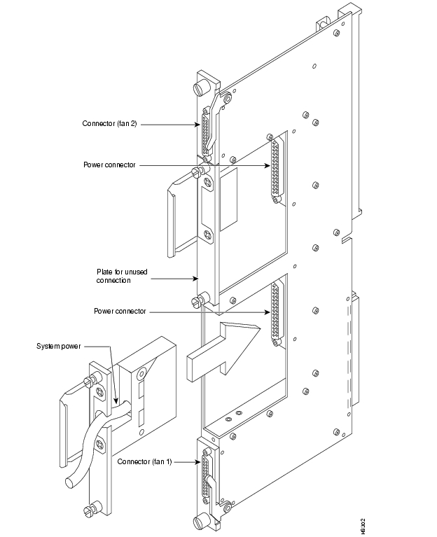
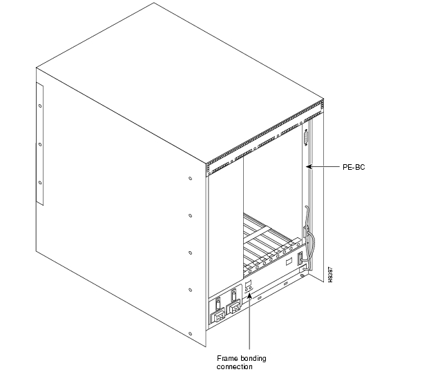
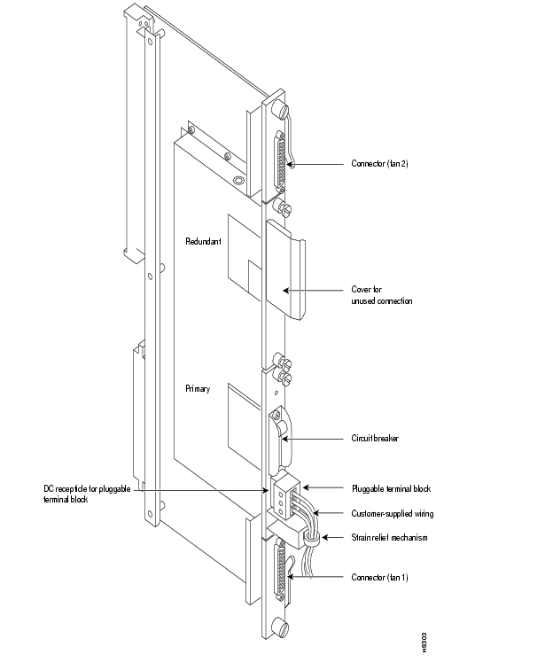
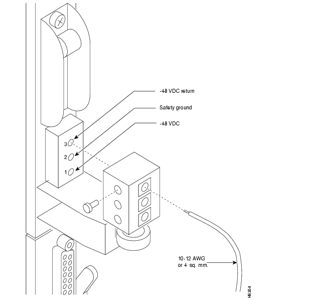
As the detailed steps on the following pages explain, installing DC power consists of attaching the three wires of the DC power source to a removable wiring block, then plugging that block into the connector on the PEM. The PEM is plugged into the PE-BC. is a view of a PE-BC (out of the card cage) with the PEM wired up and plugged into the PE-BC. shows a non-redundant DC power configuration. Note the blank plate that covers the unused connection.
Note
Figure 2-30 PE-BC and DC PEM With Plug
Warning
Remember that this is a positive ground system. Ensure that polarity of the DC input wiring is correct. Under certain conditions, connections with reversed polarity might trip the primary circuit breaker and/or damage the equipment.
Make sure the circuit breaker is in the OFF position.
To make a DC power connection:
Step 1
Step 2
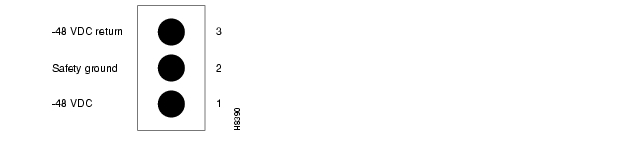
Figure 2-31 Polarities at Pluggable Terminal Block
Step 3
Step 4
Figure 2-32 Pluggable Terminal Block
Warning
For personnel safety, the green or green/yellow wire must connect to safety (earth) ground at both the equipment and at the supply side of the DC wiring.
Step 5
Step 6
Step 7
Step 8
Step 9
Warning
For personnel safety, the green or green/yellow wire must connect to safety (earth) ground at both the equipment and at the supply side of the DC wiring.
![]()
![]()
![]()
![]()
![]()
![]()
![]()
![]()
Posted: Thu Nov 11 00:33:18 PST 2004
All contents are Copyright © 1992--2004 Cisco Systems, Inc. All rights reserved.
Important Notices and Privacy Statement.