|
|

Table Of Contents
Card Installation and Node Startup
Inverse Multiplexing over ATM on Trunks
UXM-E Inverse Multiplexing ATM IMA Lines
Connecting an NTM T1 or Y1 Trunk
Connecting an NTM E1 or Subrate Trunk
Bringing Up a UXM-E in UNI or NNI Port Mode
Connecting a CVM to a T1 or J1 Line
Connecting a CVM to an E1 Line or a Subrate Trunk
Making Serial Data Connections
Making Frame Relay Connections
Maximum Connections Per Port with Signalling Protocols
Setting Up Frame Relay on a UFM
Setting Up Frame Relay on an FRM
Making Alarm Relay Output Connections
Making External Clock Connections
Connecting a Single Network Management Station
LAN Connection for the Network Management Station
Connecting a Network Management Station to Multiple Networks
Connecting the Power Supply Monitor
Checking the Power Supplies (AC Systems)
Interworking Connections in a Tiered Network
Configuring an IGX Switch to Be an Interface Shelf
Adding Connections in a Tiered Network through the CLI
Converting a Routing Node to an Interface Shelf
Card Installation and Node Startup
This chapter covers the following topics:
•
How to install the cards in an IGX node that has arrived without cards already installed. (The rack-mount models of the IGX 8420 and IGX 8430 nodes arrive with cards not installed.)
•
•
•
•
•
•
Preparing the Cards
The locations of the system cards in the IGX node depend on the hardware configuration. Primary and redundant NPMs must reside in front slot 1 and 2. The SCM must reside in back slot 1. Except for these reserved slots, cards can reside in any slot on the appropriate side of the node (but Cisco recommends that the optional ARM/ARI card set reside in the slot on the far right).
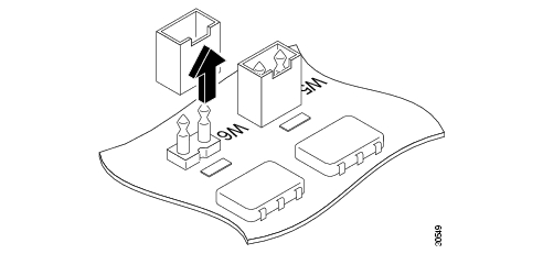
Before you install cards in a rack-mounted IGX 8420 or IGX 8430 node, to indicate whether the system is an IGX 8420 or an IGX 8430 node, you must either remove or leave a jumper switch on the SCM. (For the IGX 8410 node and standalone IGX 8420/8430 systems, Cisco sets the switch at the factory.) The switch is W6. It sits above component U7P (near the top of connector P2). To indicate an IGX 8430 node, remove the jumper. To indicate an IGX 8420, leave the jumper. Make a record of this step so you do not have to remove the SCM later to check it. See Figure 3-1.
Figure 3-1 W6 Jumper
Many card sets support Y-cable redundancy. This feature requires an extra set of cards and a Y-cable. A set of commands exists to specify, delete, and display Y-cable redundancy. For instructions on setting up Y-cable redundancy, refer to the setup section for the specific card set.
Note
A Cisco IGX node can support a configuration of up to 32 trunks.
CautionConnector pins must align with receptacles. Before card insertion, make sure that pins are straight and that card connectors and the backplane align. Insert the card gently. It might be necessary to push the edge of the card slightly to one side for alignment (this might require removing cards).
The locations for the NPMs and SCMs in a Cisco IGX:
•
— NPM in front slot number 1— SCM in back slot number 1 behind NPM front slot number 1•
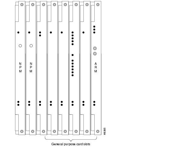
— NPMs in front slot numbers 1 and 2— SCM in back slot number 1 behind NPM front slot number 1Figure 3-2 IGX 8410 Cards, Front View
Note
CautionWhen handling the cards, wear a wrist strap to prevent damage to the cards from electrostatic discharge. The IGX 8410 cabinet has an attached wrist strap both at the front and back.
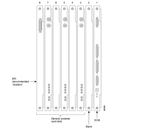
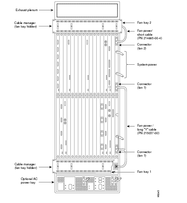
Figure 3-3 IGX 8410 Cards, Back View
Figure 3-4 IGX 8420 Card Shelf, Front View
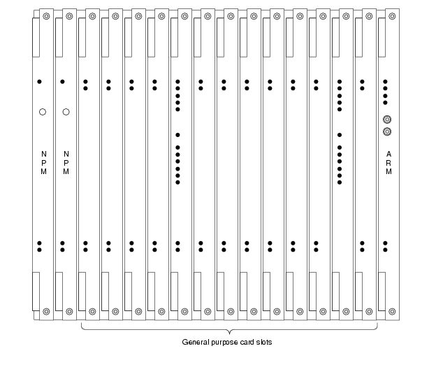
Figure 3-5 IGX 8430 Back View
Inserting the Cards
To insert a Cisco IGX module:
Step 1
Note
Step 2
Step 3
Step 4
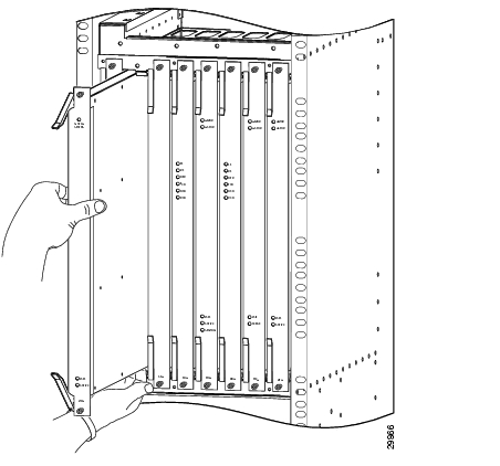
Figure 3-6 Inserting Modules
Step 5
CautionAlways use the ejector levers when disengaging or seating the modules. Failure to do so can cause erroneous system error messages, and indicate card failure. However, do not use the ejector levers to lift or support the weight of the cards.
Step 6
Making Signal Connections
The remaining sections of this chapter describe how to set up physical lines, ports, trunks, and signal connections. The Cisco WAN Switching Command Reference and Cisco WAN Switching SuperUser Command Reference provide important details on the commands appearing in this chapter.
The following trunk rates are supported:
•
•
•
•
•
The following service module (or circuit line) connections are supported:
•
— OC3 (STM1)— T3/E3— T1/E1•
— T1/E1/J1•
— T1/E1— V.35— X.21— HSSI•
— EIA/TIA-449— V.35— EIA/TIA-232D— EIA/TIA-232C•
Connecting Trunks
The sections that follow contain basic information on how to set up the two types of trunks on the IGX node. The two trunk types are FastPacket and ATM. The supported line types are OC3/STM1, T3, E3, T1, Y1, and E1. The card sets described in this section are the network trunk module (NTM). The universal switching module (UXM-E) is a dual-purpose, ATM cell-based card and has its own section that includes information for trunk-mode configuration and port-mode configuration.
Setting Up a UXM-E
To set up a UXM-E attach cables and enter commands at the command-line interface (CLI). For detailed information regarding the UXM-E, refer to the Cisco IGX 8400 Series Reference. The
Cisco IGX 8400 Series Reference contains crucial information on, for example, supported endpoints, connection types, allocation of cellbus bandwidth, and the logical trunk feature called Inverse Multiplexing Over ATM (IMA).You can specify the mode of the UXM-E through Cisco WAN Manager or the CLI. The UXM-E card set goes into the mode determined when you activate the first port. If you activate a logical port to be a trunk by using the uptrk command, for example, the UXM-E goes into trunk mode. If you use upln to activate a line as a UNI port to CPE or an NNI to another network, the UXM-E goes into port mode.
For a summary of commands you use to bring up an IGX node, refer to the section "IGX Configuration Summary" on page 49 at the end of this chapter.
Bringing Up a UXM-E Trunk
If you are not familiar with precautions for card insertion, see the section "Preparing the Cards" on page 1.
To attach the cables to a back card:
Step 1
Step 2
Step 3
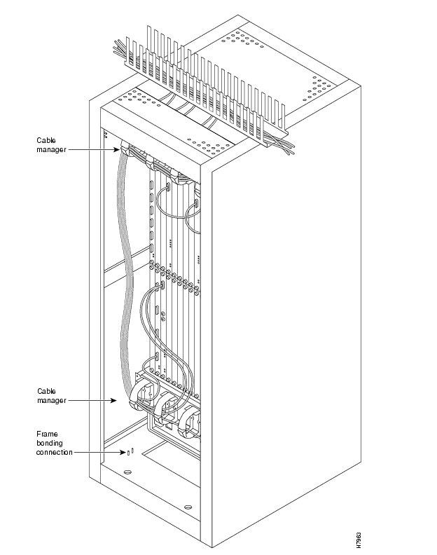
Figure 3-7 Cable Management
The following is the command sequence for bringing up the trunk. You must bring up the trunk before you add connections. For detailed command descriptions, see the command references.
Step 1
dspcds
Step 2
Note
Step 3
To specify an IMA trunk through the CLI, enter uptrk slot.first_line-last_line. The line numbers must be contiguous.
Step 4
Step 5
Step 6
cnfclksrc
Step 7
Step 8
Inverse Multiplexing over ATM on Trunks
An IMA lets you group physical T1 or E1 lines to form a logical trunk. A logical trunk consisting of more than one T1 or E1 line supports connections with data rates that are much higher than the T1 or E1 rate. System software lets you specify IMA so that one or more physical lines within the logical trunk can serve as backup if a line fails. IMA characteristics are as follows:
•
•
•
•
To specify the range of ports for an IMA trunk, you can use either Cisco WAN Manager or the command-line interface (CLI). To define an IMA trunk on the CLI, use the uptrk command:
uptrk slot.start_port-end_port
For example, you could enter uptrk 8.1-4. Subsequently, you would refer to this logical trunk by using only the slot number and first port number—8.1 in this example—when you use other commands, such as addtrk, deltrk, cnftrk, and so on. Commands for viewing IMA information also include dspportstats, dspphyslns, dsptrkcnf, dspfdr, dspnode, and dspphyslnstathist.
Adding an IMA Feeder Trunk
To add the UXM-E feeder trunk, you can use either Cisco WAN Manager or the CLI. To define an IMA trunk on the CLI:
Step 1
uptrk slot.group-member(s)
Step 2
cnftrk slot.primary link
Step 3
addshelf slot.primary link shelf type
Note
Adding Links to an IMA Feeder Group
To add links to an IMA group, you can use either Cisco WAN Manager or the CLI. To add a link to an IMA on the CLI:
Step 1
dsptrks
Step 2
cnftrk slot.primary link
Step 3
Step 4
Removing Links from an IMA Feeder Group
To remove links from an IMA group, you can use either Cisco WAN Manager or the CLI. To remove a link from an IMA group on the CLI:
Step 1
Step 2
Step 3
Step 4
Step 5
cnftrk slot.primary link
Note
UXM-E Inverse Multiplexing ATM IMA Lines
This feature allows the extension of the IMA protocol to UXM-E line interfaces, which substantially reduces equipment and interface costs for customers requiring IMA line interfaces and trunks and high bandwidth demand for ATM. It reduces costs by bundling multiple physical T1/E1 lines into a logical line enlarging traffic bandwidth. This makes it unnecessary to upgrade access lines to higher speed services such as T3/E3.
Note
To specify the range of ports for an IMA line, you can use either Cisco WAN Manager or the command-line interface (CLI). To define an IMA line on the CLI, use the upln command:
upln slot.group-member
For example, you could enter upln 8.1-4. Subsequently, you would refer to this physical line by using only the slot number and first group member—8.1 in this example—when you use commands, such as upln, dnln, cnfln, and so on. Following the activation of an IMA line group, the logical port will be created with the primary line port as the port number.
Commands for viewing IMA line information also include dsplncnf, dsplns, dspports, dspport, dspphyslnstathist and dspphyslnstatcnf.
Note
Connecting an NTM T1 or Y1 Trunk
The T1 trunk connections use the NTM front card and the BC-T1 back card. Japanese Y1 connections use the NTM front card and the BC-Y1 back card. The procedure for making Y1 connections is the same as for T1 connections described below.
Make the T1 connections as follows:
Step 1
Step 2
Step 3
The back slot line numbers correspond to the back slot number in which the BC-T1 card resides. Record the back slot number of each line. These numbers are necessary for configuring the system after you complete hardware installation.
Note
Connecting an NTM E1 or Subrate Trunk
The E1 trunk connections use the NTM front card and the BC-E1 back card. Subrate E1 connections use the NTM front card and the BC-SR back card. The E1 trunk interface card BC-E1 contains the E1 trunk connector (G.703 Input/Output) that is located at the top of the back card. The BC-E1 faceplate has four 75-ohm BNCs.
Note
Make the E1 connections as follows:
Step 1
Note
Step 2
Step 3
Record the slot numbers of the NTM/BC-E1 card set. You need these numbers when you configure the system.
Setting Up a UXM-E
This section consists of descriptions of how to set up a port-mode UXM-E and a trunk-mode UXM-E. The descriptions consist of the steps for attaching cables and entering commands at the command line interface (CLI). For detailed information regarding the UXM-E, refer to the
Cisco IGX 8400 Series Reference. The Cisco IGX 8400 Series Reference contains crucial information on, for example, supported endpoints, connection types, allocation of cellbus bandwidth, and the logical trunk feature called Inverse Multiplexing over ATM (IMA).You can specify the mode of the UXM-E through Cisco WAN Manager or the CLI. The entire UXM-E card set goes into the mode determined by the first port you activate. If you activate a logical port to be a trunk by using the uptrk command, for example, the UXM-E goes into trunk mode. If you use upln to activate a line as a UNI port to CPE or an NNI to another network, the UXM-E goes into port mode.
For a summary of commands you use to bring up an IGX node, refer to the section "IGX Configuration Summary" on page 49.
Bringing Up a UXM-E in UNI or NNI Port Mode
If you are not familiar with card insertion, see the section "Preparing the Cards" section.
To attach the cables:
Step 1
Step 2
Step 3
To activate a port-mode UXM-E:
Step 1
Step 2
Step 3
Step 4
Step 5
Step 6
Step 7
Step 8
Step 9
Step 10
Note
Step 11
Step 12
Installing Voice Cards
This section describes how to install the voice cards. See the section titled " IGX Configuration Summary" for a summary of the commands that apply to circuit lines and voice connections. The two voice card sets are the channelized voice module (CVM) and the universal voice module (UVM). These cards can also carry channelized data. The serial data card sets are the HDM and LDM. This section also describes the considerations for using the TDM Transport feature on the CVM.
Connecting a CVM to a T1 or J1 Line
Voice or data connections on a T1 line use the CVM front card and the BC-T1 back card. Japanese J1 connections use the CVM front card and the BC-J1 back card. The procedure for making J1 connections is the same as for T1 connections. Make the T1 connections as follows:
Step 1
Step 2
Step 3
The back slot line numbers correspond to the back slot number in which the BC-T1 card resides. Record the back slot number of each line. These numbers are necessary for configuring the system after you complete hardware installation.
Note
Connecting a CVM to an E1 Line or a Subrate Trunk
Channelized voice or data connections on an E1 line use the CVM front card and the BC-E1 back card. Subrate E1 connections use the CVM front card and the BC-SR back card. The E1 trunk interface card BC-E1 contains the E1 connector (G.703 Input/Output) that resides at the top of the back card. The BC-E1 faceplate has four, 75-ohm BNCs.
Note
Make the E1 connections as follows:
Step 1
Note
Step 2
Step 3
The back slot line numbers correspond to the back slot number in which the BC-E1 card resides. Record the back slot number of each line. These number are necessary for configuring the system after installation is complete.
The next section describes a specialized version of data transmission service called TDM Transport. It applies to older, non-Cisco WANs.
TDM Transport on the CVM
This section describes how to plan for use of the Time Division Multiplexing Transport (TDM Transport) feature. Note that TDM Transport requires Rev. C firmware on all connected CVMs or CDPs that use this feature. Refer to the TDM Transport description in the Cisco IGX Reference for details on Rev. C firmware features and limitations. Refer to the Cisco WAN Switching Command Reference for a description of the command parameters in related commands.
Before adding a bundled connection under TDM Transport, consider the following:
•
•
•
•
•
•
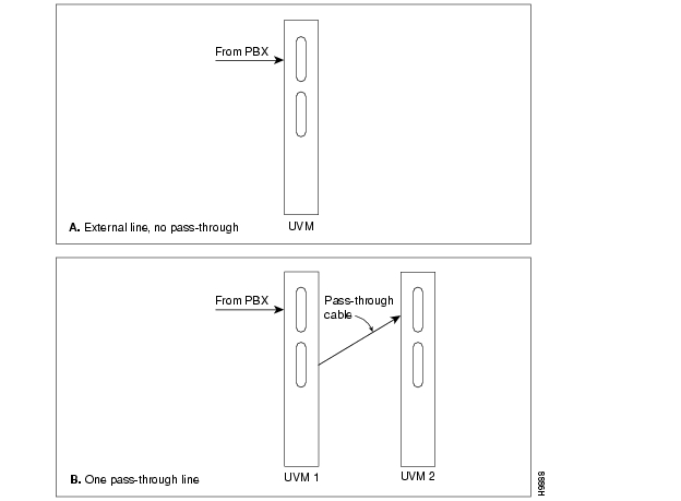
Connecting a UVM to T1 Lines
Voice or data connections on a T1 line use the UVM front card and the BC-UVI-2T1EC back card. The procedure for connecting the T1 lines is as follows:
Step 1
Step 2
•
•
•
•
For a description of the pass-through feature, refer to the Cisco IGX 8400 Series Reference.
Record the back slot number and port number of each line. These numbers are necessary for configuring the system after you complete hardware installation.
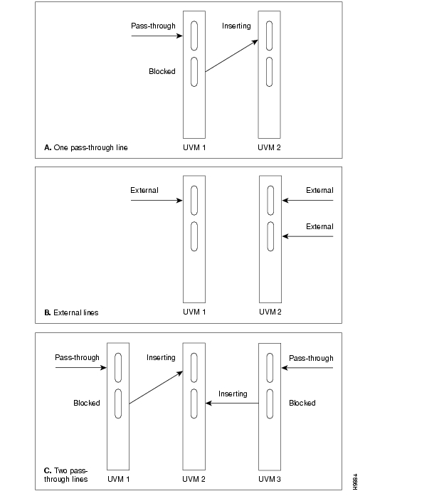
Figure 3-8 Pass-Through and Standard (External) UVM T1 Cabling
Connecting a UVM to E1 Lines
Voice or data connections on an E1 line use the UVM front card and the BC-UVI-2E1EC back card. The procedure for connecting the E1 lines is as follows:
Step 1
Step 2
Step 3
Step 4
Step 5
•
•
•
For a description of the pass-through feature, refer to the Cisco IGX 8400 Series Reference.
Figure 3-9 Pass-Through and Standard (External) UVM E1 Cabling
The back slot line numbers correspond to the slot number in which the BC-UVI-2E1EC card resides. Record the back slot number and port number of each line. These numbers are necessary for configuring the system after you complete hardware installation.
Connecting a UVM to J1 Lines
Voice or data connections on a J1 line use the UVM front card and the BC-UVI-2J1EC back card. The procedure for connecting the J1 lines is as follows:
Step 1
Step 2
If the intended compression for voice channels is LDCELP and the number of channels on a J1 line exceeds 16, install cabling for pass-through. For the steps that follow, refer to for an illustration of the possible UVM cabling arrangements. Note that, in Example B, the number of channels has not exceeded the UVM capacity, so pass-through is unnecessary.
•
•
•
For a description of the pass-through feature, refer to the Cisco IGX 8400 Series Reference.
Figure 3-10 Pass-Through and Standard (External) UVM J1 Cabling
The back slot line numbers correspond to the slot number in which the BC-UVI-2J1EC card resides. Record the back slot number and port number of each line. These numbers are necessary for configuring the system after you complete hardware installation.
Making Serial Data Connections
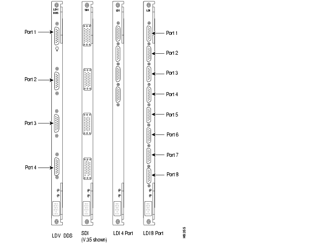
The low-speed data module (LDM) and high-speed data module (HDM) card sets provide serial data service. Each of these front cards uses a variety of back cards.
The LDM front card uses the 4-port or 8-port version of the low-speed data interface (LDI) back card for EIA/TIA-232C/D (V.24) connections. The connection ports are labeled PORT 1 through PORT 4 or PORT 1 through PORT 8. See for illustrations these back cards. For instructions on configuring an LDI port for DTE or DCE mode, refer to the section Configuring the Mode of an LDI Port " Configuring the Mode of an LDI Port."
The HDM front card works with four types of serial data interface (SDI) back cards. SDIs are available. These are V.35, EIA/TIA-449/422, EIA/TIA-232D, and EIA/TIA-232C (V.24). (X.21 uses EIA/TIA-449 plus an adapter cable.) Each type of SDI has four connection ports, which are labeled PORT 1 through PORT 4. An example SDI card appears in .
When you connect an HDM or LDM port, use the shortest reasonable cable length for each port.
Figure 3-11 SDI and LDI Faceplates
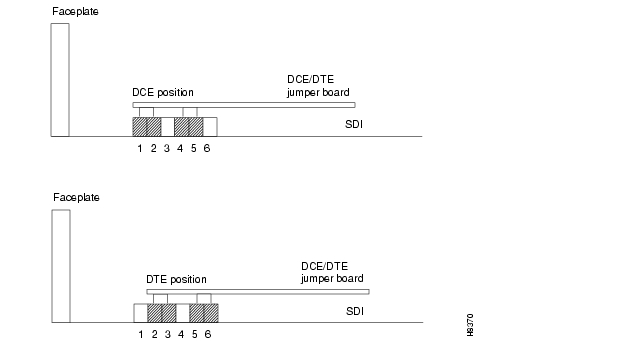
Configuring the Port Modes of the HDM Back Cards
Small jumper boards on the back card determine whether the mode of the port is DTE or DCE. The factory-set modes of the SDI ports alternate DCE with DTE. The steps that follow describe how to change the mode of the port. For the two modes, the rows on the back card jumper connector that are occupied by the jumper card are:
•
•
Note
To change the mode on a port to DTE, position the jumper board for that port as follows:
CautionTo prevent damage to the SDI cards, wear a wrist strap and clip the strap to the enclosure.
Step 1
•
•
Step 2
If a port is in DTE mode and needs to be changed to DCE, plug the jumper board into the connector receptacle pin rows closest to the SDI faceplate. (See .) These rows are 1, 2, 4, and 5.
Figure 3-12 Changing the Mode on an SDI Card
HDM and LDM Redundancy
Optional redundancy for HDM and LDM cards can be provided with a second front and back card set and a Y-cable connection on each port to the customer data equipment.
Note
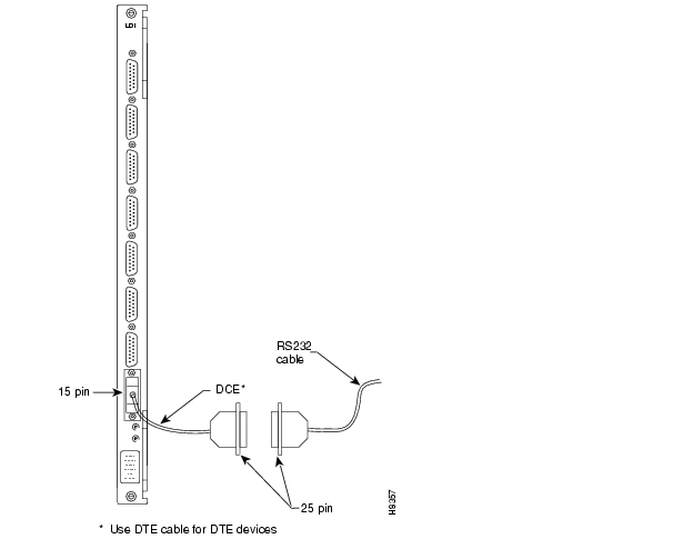
Configuring the Mode of an LDI Port
Each port on an LDI card uses an adapter cable. For a list of LDI adapter cables, refer to Appendix C, " ." Each cable does the following:
•
•
•
See for an example. In , the adapter cable makes the port a DCE port. Circuits on the card test certain pins on the cable then configure the port as DTE or DCE.
Figure 3-13 Connecting a DTE or DCE Adapter Cable to an LDI
Making Frame Relay Connections
This section outlines how to establish Frame Relay service by setting up a universal frame module (UFM) or a Frame Relay module (FRM). The information includes details for T1, E1, HSSI, V.35, and X.25 interfaces. Detailed descriptions of the Frame Relay commands appear in the Cisco WAN Switching Command Reference. Specific cabling requirements for the UFI back cards on the UFM-U appear in the UFM-U description in the Cisco IGX 8400 Series Reference.
Maximum Connections Per Port with Signalling Protocols
For any Frame Relay card set that has a maximum frame length of 4510 bytes, the type of signaling protocol you can (optionally) specify with cnffrport results in a limit on the number of connections per physical or logical port. The maximum number of connections per port for each protocol is:
•
•
•
Neither addcon nor cnffrport prevents you from adding more than the maximum number of connections on a port. (You might, for example, use cnffrport to specify an LMI when too many connections for that particular LMI already exist.) If the number of connections is exceeded for a particular LMI, the LMI does not work on the port, the full status messages that result are discarded, and LMI timeouts occur on the port. A port failure results and also subsequently leads to a-bit failures in other segments of the connection path.
Setting Up Frame Relay on a UFM
Channelized and unchannelized versions of the UFM card sets exit. The channelized front cards UFM-4C and UFM-8C operate with T1 and E1 interfaces, and the unchannelized front card UFM-U operates with V.35, X.21, and HSSI interfaces.
The back cards have the following terminations:
•
•
•
•
•
•
If the installation includes Y-cable redundancy, first read the section " Y-Cable Redundancy on the UFMs."
Y-Cable Redundancy on the UFMs
Redundancy for a Frame Relay port is possible with a second card set and the appropriate Y-cable. The card redundancy kit for UFM contains a second UFM/UFI card set and Y-cables to interconnect the ports on the two back cards. The forthcoming section titled " Setting Up Frame Relay Ports and Connections (UFM)" includes the step for configuring Y-cable redundancy.
Refer to the cabling description in the UFM-U section of the Cisco IGX 8400 Series Reference for descriptions and part numbers of all cables for unchannelized UFMs.
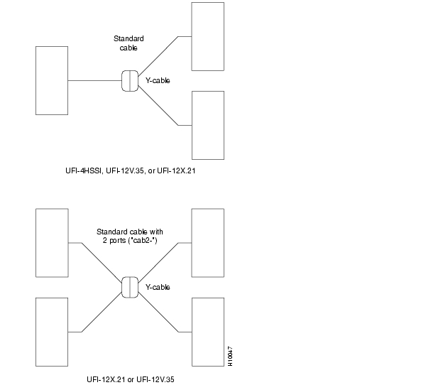
shows the Y-cable arrangement for standard cables that support one or two ports. The diagram for single-port cables applies to all back cards. The dual-port cables connect to only a V.35 or X.21 UFI. The Y-cable connects to the back card, and the standard cable runs between the access device or CPE and the base of the "Y."
Y-cable redundancy is not allowed between different line types, such as a UFI-8T1-DB-15 and a UFI-8E1-DB-15. The dspyred display shows any conflict in reverse video. (See the descriptions of the upln (or upcln) and upfrport commands in the Cisco WAN Switching Command Reference.)
The commands that relate to Y-cable redundancy are addyred, delyred, dspyred, and ptyred. After you have installed the cards in adjacent slots and connected the cables, use the addyred command to direct the node to recognize the card redundancy. See the Cisco WAN Switching Command Reference for descriptions of.the commands.
Figure 3-14 Y-Cable Redundancy with Single and Dual-Port Cabling
Connecting UFM Cabling
For important details on standard cables and Y-cables for the UFI back cards, refer to the cabling description in the UFM-U section of the Cisco IGX 8400 Series Reference.
Take the following steps after you have inserted the cards according to the information on installing cards in the section titled "Preparing the Cards" section. Connect the cables as follows:
Step 1
Step 2
Step 3
Step 4
Step 5
Setting Up Frame Relay Ports and Connections (UFM)
This section outlines the steps for setting up and deleting Frame Relay ports, adding connections, and bundling connections. If a port has multiple PVCs, you can optionally bundle the connections. Bundling facilitates network meshing. You can specify connection bundling during parameter specification in the Add Connection (addcon) command: if you press Return without specifying a DLCI during port specification, the system prompts for bundling information. See the "Frame Relay Connections" chapter in the Cisco WAN Switching Command Reference for details.
Use either a Cisco WAN Manager workstation an IGX control terminal to do the following tasks. For detailed command descriptions, see the Cisco WAN Switching Command Reference.
Step 1
Step 2
A UFM-U does not require activation with the upln command.
Step 3
Step 4
Step 5
Step 6
Step 7
Step 8
If you do not know the Frame Relay class intended for entry with the addcon command, determine which Frame Relay class number to use. Use the Display Frame Relay Classes (dspfrcls) command to see the parameters that each class specifies. To modify parameters in a class, use Configure Frame Relay Class (cnffrcls).
Step 9
Optionally, you can set the channel priority by using the cnfchpri command. Normally, the system-default priority is adequate.
Commands for T1/E1 Frame Relay
To specify logical ports on a T1 or E1 interface, use addfrport. The addfrport command assigns a logical port number to a physical line and a range of 1 or more DS0s/timeslots. Use the logical port number to activate a port (upfrport), add connections (addcon), or display statistics (dspportstats). For example, after you add logical port 14.60 2.1-24 with addfrport, you up this logical port by entering "upfrport 14.60." The maximum number of logical port numbers on a UFM-C is 250. Use dspfrport to display logical ports.
Deleting a Frame Relay Port
Delete a logical port by executing the delfrport command. Executing delfrport dissolves any groups of DS0s/timeslots and unassigns all DS0s/timeslots on the logical port. (Note that, before you delete a Frame Relay port, you must delete any connections on the port with delcon.) After deleting a logical port with delfrport, you can de-activate the physical port with dnport.
Setting Up Frame Relay on an FRM
Four types of interfaces are available for the FRM. The back cards have the following terminations:
•
•
•
•
Cabling requirements for the Frame Relay interfaces are in Appendix C, " ."
Take the following steps after you have inserted the cards according to the general information on installing cards in the section "Preparing the Cards" section. To connect a cable:
Step 1
Step 2
Step 3
Record the slot number of each line. These numbers are necessary for configuring the system.
Port Mode Selection for V.35 and X.21
The position of a small jumper board at each port determines whether it is a DCE or a DTE.
Warning
Only qualified personnel should open the cabinet door.
CautionTo prevent damage to the FRI cards, ground yourself before handling IGX cards by clipping a grounding strap to your wrist, and clipping the wrist strap lead to the enclosure.
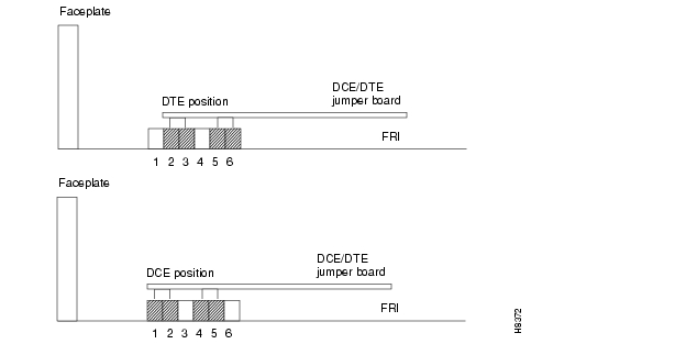
A small jumper card near each connector on the back card selects the port's mode. The factory-set modes alternate between DCE and DTE. The steps that follow describe how to change the mode of a port. The relation between back card row numbers and the port mode is as follows:
•
•
Note
Note
To change the mode of an interface, reposition the jumper board for the port as follows:
Step 1
•
•
•
Step 2
To change to DCE, plug the jumper board into the connector receptacle pin rows closest to the FRI faceplate. (See .) The rows for DCE mode are 1, 2, 4, and 5.
Step 3
Note
Step 4
Figure 3-15 Setting the Port Mode (DTE/DCE) on an FRI
Frame Relay Card Redundancy
Optional redundancy on a Frame Relay port is possible with a second FRM/FRI card set and a Y-cable connection on each applicable port. The section " "Setting Up Frame Relay Ports and Connections (FRM)" section. includes the step for configuring Y-cable redundancy. The card redundancy kit contains a second FRM/FRI card set, Y-cables to interconnect the ports on the two back card, and four, 200-ohm DCE/DTE jumper cards if the back cards are either FRI-V.35s or FRI-X.21s. (The DCE or DTE port applies to only V.35 or X.21 interfaces.) Make sure that the firmware revision of the FRM in the kit matches the firmware in the installed FRM. Model firmware supports V.35 and X.21 interfaces. Model E firmware supports T1 and E1 interfaces.
When you install a redundant card set with either a V.35 or X.21 interface, you must change the daughter cards on the existing FRI that specify DCE or DTE mode at each port. Install the higher impedance (200 ohms) version cards that are in the Y-cable kit.
Y-cable redundancy is not allowed between inconsistent back card types, such as an FRI T1 and an FRI V.35. The dspyred display shows any conflict in reverse video. (Refer also to the descriptions of the upcln and upfrport commands in the Cisco WAN Switching Command Reference.)
After the hardware is installed, use the addyred command to reconfigure the node to recognize the card redundancy. Refer to the Cisco WAN Switching Command Reference for more information on the commands addyred, delyred, dspyred, and ptyred.
Setting Up Frame Relay Ports and Connections (FRM)
This section outlines the steps for setting up and deleting Frame Relay ports, adding and configuring connections, and bundling connections. As the steps show, some commands apply to channelized connections (T1, E1, or J1) but not to unchannelized connections (V.35 or X.21). Use either the IGX control terminal or a Cisco WAN Manager workstation to execute the commands. For parameters and other details on the commands, refer to the Cisco WAN Switching Command Reference.
If a port has multiple PVCs, you can optionally bundle the connections. Bundling facilitates network meshing. You can specify connection bundling during parameter specification in the Add Connection (addcon) command: if you press Return without specifying a DLCI during port specification, the system prompts for bundling information. See the "Frame Relay Connections" chapter in the Cisco WAN Switching Command Reference for details.
Step 1
Step 2
Step 3
Note
Step 4
For V.35 and X.21 interfaces, skip the next three steps.
Step 5
Step 6
Step 7
Step 8
Step 9
If you intend to bundle connections, use cnffrport to set the Port ID to the DLCI planned at the near-end connections. Setting the PortID is optional for non-bundled connections.
Step 10
Step 11
Step 12
Step 13
Commands for T1/E1 Frame Relay
To specify logical ports on a T1 or E1 interface, use addfrport. The addfrport command assigns a logical port number to a group of one or more DS0s/timeslots. The slot number and the lowest number in the user-specified DS0/timeslot group form the logical port number. Use the logical port number to activate a port (upfrport), add connections (addcon), or display statistics (dspportstats). For example, after you add logical port 14.1-6 (6 DS0s/timeslots) with addfrport, you activate (or up) this logical port by entering "upfrport 14.1." Use dspfrport to display logical ports.
Deleting a Frame Relay Port
Executing delfrport dissolves any groups of DS0s/timeslots and unassigns all DS0s/timeslots on the logical port. To delete a logical port:
Step 1
Step 2
Step 3
Step 4
Making Alarm Relay Output Connections
To install an alarm relay module (ARM) card set:
Step 1
Step 2
Step 3
Step 4
Step 5
See the section "Initial Startup of the IGX" on page 46, when the system is ready for power.
The steps that follow show how to set up an ARM card set after the physical installation is complete. This is done from the IGX control terminal or the Cisco WAN Manager workstation. For details on each command used, refer to the Cisco WAN Switching Command Reference.
Step 1
Step 2
Step 3
Step 4
Step 5
Step 6
Step 7
Step 8
Step 9
Alarm output connections are made at the DB37 connector on the ARI card. The connector pin assignments with the alarm signal names are listed in . (See Appendix C, " .")
Table 3-1
ARI Alarm Connector PinOuts
shows the unassigned connector pins.
Table 3-2 Unassigned Connector Pins
Making External Clock Connections
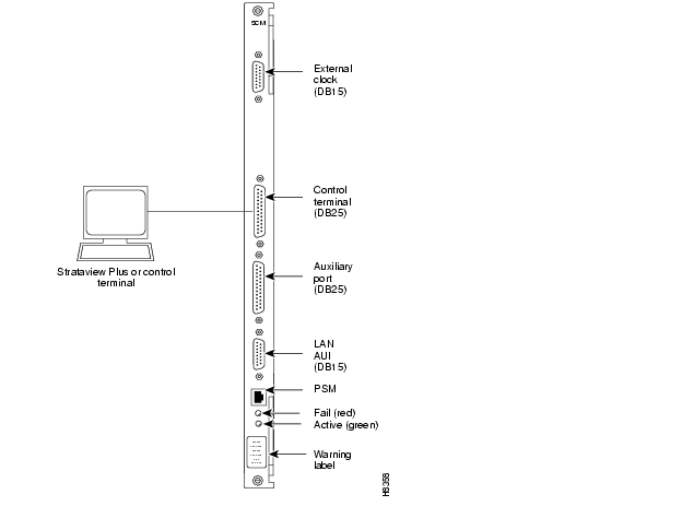
The DB-15 connector labeled Ext Clocks on the faceplate of the SCM connects two external sources for a high-stability clock (primary and redundant). These inputs are 1.544 MHz or 2.048 MHz. In addition, one of the trunk or circuit line inputs can also serve as a source of timing for the node. If you do not select a clock source, the clock source is the internal IGX clock.
Two separate clock inputs exist. The primary clock source is A, and the secondary clock source is B. One or both of these can be either 1.544 Mbps or 2.048 Mbps. For a list of connector pin assignments, see Appendix C, " ."
Attaching Peripherals
A network must have at least one control terminal (or a Cisco WAN Manager workstation if you wish to collect statistics) attached, along with a network printer for printing out the status of the system. The SCM has three ports for attaching peripherals to an IGX node. These ports are Control Terminal, LAN AUI, and AUX port.
For the Cisco TAC to perform remote troubleshooting, a modem must connect to the network. This is a requirement for all Cisco service plans. The following sections provide procedures for attaching peripherals to the IGX node. Be sure to read the manufacturers' literature to ensure that the equipment is ready before attempting to connect it to the IGX node.
Connecting a Single Network Management Station
To use network management, at least one node in a Cisco WAN switching network running
Release 7.2 or higher software must have a Cisco WAN Manager workstation connected. The workstation connects to the AUI Ethernet LAN port on the SCM.The Cisco WAN Manager workstation can be used to configure and maintain all nodes in a network. For instructions on using the Cisco WAN Manager workstation, see the Cisco StrataView Plus Operations Guide.
If only a single NMS station is connected and the network is relatively small, you can use a serial EIA/TIA232 port—the Control Terminal port.
The appendix titled " " lists the control terminals supported by the IGX 8410 node and the configuration settings. Appendix C, " " has the pin assignments for the IGX 8410 control terminal port.
Attach the control terminal to the SCM. (See .)
Step 1
Step 2
Figure 3-16 Connecting the Control Terminal
Step 3
Step 4
Step 5
Step 6
Note
9,600 bps. When the transition to on-line occurs, the speeds match, so the display becomes readable.
LAN Connection for the Network Management Station
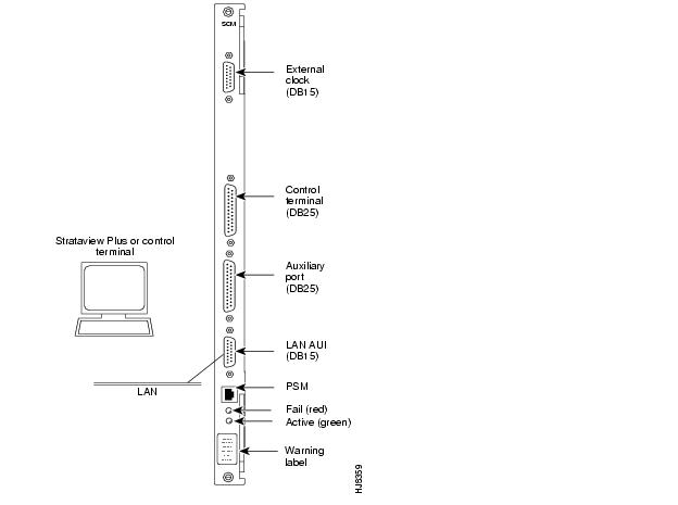
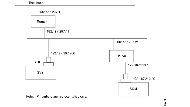
If the network is large or extensive network statistics are needed, an Ethernet port (LAN port) should be used. Larger networks produce a greater flow of statistics data between the node and the Cisco WAN Manager workstation, so a higher speed Ethernet port is suitable. illustrates this connection. Accessing a node over an Internet connection requires the operator to use cnflan to enter the Internet Protocol (IP) address, IP subnet mask, TCP service port, and gateway IP address.
Figure 3-17 LAN Connection to SCM
Configuring the LAN Port
Note
Note
Step 1
Step 2
•
192.187.207.200 hedgehog
192.187.210.30 sanfran
Note
Note
Step 3
The cnflan command configures the node's communication parameters so that the node can communicate with a Cisco WAN Manager terminal over an Ethernet LAN using the TCP/IP protocol. The parameters contain address information about the Ethernet TCP/IP network that is used to connect the Cisco WAN Manager workstation to an IGX node. The values used must conform to those of the network and should be supplied by the Ethernet network administrator.
The cnflan command has the following parameters:
•
•
•
•
A cnflan screen looks like this:
D2.cb1 LAN superuser IGX 8410 9.3 Feb. 27 2000 14:23 PSTActive IP Address: 192.187.207.21IP Subnet Mask: 255.255.255.0TCP Service Port: 5130Default Gateway IP Address: 192.187.207.1Maximum LAN Transmit Unit: 1500Ethernet Address: 00.55.43.00.04.55Control Socket - ReadyBase Socket Descriptor - 1Socket ClosedLast Command: cnflanNext Command:The active IP address for the workstation has been entered as the IP address selected previously for the node, 192.187.207.21. The IP Subnet mask is entered as 255.255.255.0 for a Class C LAN network. The TCP service port is entered as 5120. Because the workstation and node are on different networks in this example, a gateway address of 192.187.207.1 has been entered. If the workstation and node are both on the same network, no gateway address is needed. The "Maximum LAN Transmit Unit" and "Ethernet Address" parameters are not configurable by the cnflan command. The "Ethernet Address" is a hardware address ("burned into the NPM card") that is unique to each NPM card.
Step 4
Step 5
ping sanfranStep 6
D2.cb1 LAN cisco IGX 8410 9.3 Feb. 27 2000 14:27 PSTActive IP Address: 192.187.207.21IP Subnet Mask: 255.255.255.0TCP Service Port: 5130Default Gateway IP Address: 192.187.207.1Maximum LAN Transmit Unit: 1500Ethernet Address: 00.55.43.00.04.55Control Socket - ReadyBase Socket Descriptor - 1Open Socket Descriptor - 2Last Command: dsplanNext Command:
Note
Note
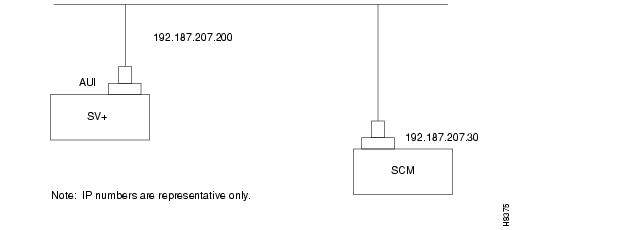
Figure 3-18 SV+ LAN Connection via Router to an IGX Node
Figure 3-19 SV+ LAN Connection to an IGX Node (No Gateway)
Step 7
Connecting a Network Management Station to Multiple Networks
When a network management station has more than one serial port, ports can connect to different networks. When the number of workstation serial ports is less than the number of networks to be managed, a terminal server is necessary to obtain a communications link to the separate networks. This subject is covered in the Cisco WAN Manager Installation publication.
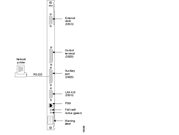
Connecting the Printer
At least one node in the network should have a printer connected. The printer connects to the AUX port on the SCM.
The printer is used to print information about network operation. It can be configured to print maintenance information on a regular basis, and it can print specific diagnostic information when necessary. Instructions on using the printer for this purpose are in the Cisco WAN Switching Command Reference. (Appendix A in the Cisco WAN Switching Command Reference lists all commands. The printer-related commands have the characters "prt." somewhere in the command mnemonic.)
Attach the printer to the IGX node as follows:
Step 1
Step 2
Step 3
Figure 3-20 Connecting a Network Printer
Step 4
Step 5
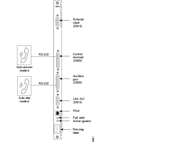
Connecting a Modem
Two modems can be connected to the IGX node to provide access for remote troubleshooting and for remote alarm logging. (See .) Each connection between the SCM and a modem requires a special cable and setup procedure.
The modem that provides access for remote troubleshooting from the Cisco TAC office (TAC-to-IGX modem) connects to the Control Terminal port on the SCM. Typically, the modem connects to the telephone wall jack with a direct-dial line. You can reach the TAC through Cisco Customer Engineering.
The modem that is used to provide remote alarm logging (IGX-to-TAC modem) is connected to the AUX port on the SCM. This modem connects to a wall jack using a standard telephone line.
Figure 3-21 Connecting Modems to an IGX Node
Connecting the Power Supply Monitor
The power supply monitor (PSM) is a connector with outputs that signal an AC power supply alarm. Cisco provides no equipment that connects to the PSM connector, so user-supplied equipment is necessary. Refer to the Cisco IGX 8400 Series Reference publication for a description of the PSM outputs.
Initial Startup of the IGX
This section describes checkout procedures to follow after the hardware is in place and ready to receive power. The section "IGX Configuration Summary" section appears later in this chapter. It summarizes the steps and lists the commands for bringing up the system.
Before using the IGX node, be sure the following procedures are complete:
Step 1
Step 2
Step 3
Step 4
Step 5
Step 6
Step 7
Step 8
Step 9
Step 10
Step 11
CautionIf the FAN 2 connector on the PE-BC is unused, be sure not to plug the control terminal
cable into FAN2.
Step 12
Step 13
Step 14
Step 15
•
•
•
•
Step 16
NPM Startup Diagnostic Test
The IGX software contains a group of diagnostic tests that run on the system's hardware at power-up. The startup diagnostic either passes or fails the NPM(s). The test result is displayed on the control terminal screen as pass or fail. The pass screen looks like this:
**************************************************************************************Release 7 Boot power up diagnostics starting.68000 Internal Registers test passed.68000 clock test passed.Static RAM test passed.TDM memory test passed.Fast RAM test passed.BRAM test passed.Dynamic RAM test from Hex Address 400000 to Hex Address 9FFFFFRelease 7 Power up diagnostics complete.**************************************************************************************The fail screen looks like this:
**************************************************************************************Release 7 Boot power up diagnostics starting.68000 Internal Registers test passed.68000 clock test passed.Static RAM test passed.TDM memory test passed.Fast RAM test passed.BRAM test failed.Remove and reinsert this NPM to see if it fails again.**************************************************************************************If an NPM fails the power-up diagnostic, the boot process does not finish. If this failure occurs:
Step 1
Step 2
Step 3
Step 4
Card Self Test
IGX software includes internal diagnostic routines that periodically test a card's performance. The diagnostics automatically run in background and do not disrupt normal traffic. If a failure occurs during the test, the red FAIL LED turns on. You can also view status on a terminal with dspcd.
The report of a card failure remains until cleared. On the CLI, clear a card failure by using resetcd. Two types of resets exist. The reset-failure clears the event log of failures detected by the test. It does not disrupt operation. A reset-hardware resets the card's firmware: it reboots the firmware (momentarily disabling the card) and, if a redundant card exists, switches over to the standby card.
Inspecting Status Lights
Check the status lights on the system unit cards. shows the lights for normal status where n+1 redundancy exists for NTM and CVM cards.
Table 3-3 Component Status After Power-Up
NPM
1
1
-
CVM
-
-
-
UVM
-
-
-
NTM
-
all
-
BC-T1/E1
-
all
-
BC-SR (Subrate)
-
all
-
HDM/LDM
-
all
-
SDI/LDI
-
all
-
FRM
-
all
-
UFM
-
all
-
SCM
1
0
-
ARM
1
-
-
Power Supplies
All
-
-
1 Standby status is indicated by no lights on.
•
•
Checking the Power Supplies (AC Systems)
The means for verifying the correct power supply voltages are the DC Okay and AC Okay LEDs on each power supply. If either of these LEDs is off, a problem exists in relation to that supply. Power supplies are not field-adjustable. If a power supply voltage is out of tolerance, replace the supply with one known to be within tolerance. Refer to the section on AC power supply replacement in Chapter 4, " Troubleshooting".
Note
IGX Configuration Summary
This section outlines the steps and names the commands for configuring a network. This section is not an exhaustive presentation. For detailed descriptions of the commands, refer to the Cisco WAN Switching Command Reference publication or the Cisco WAN Switching SuperUser Command Reference publication.
You can configure the IGX node through commands you enter at the control terminal or, if you have access, at a Cisco WAN Manager Network Management Station. Note that certain features are paid options, which TAC personnel must enable before you add the corresponding connections. Examples of paid options are Frame Relay and ABR with ForeSight.
For IGX configuration, the control terminal has system access either through a local control port (over an EIA/TIA-232 or Ethernet TCP/IP link) or from a control terminal screen on a Cisco WAN Manager Network Management Station (NMS). Remote control terminal access is possible using a Virtual Terminal (vt) command if the node has been configured with a name (cnfname) and at least one trunk has been established to the network.
The basic tasks to configure an IGX node are as follows:
•
— Configure the node name (cnfname).— Configure the time zone (cnftmzn).— Configure the LAN interface (cnflan).— Configure the auxiliary or terminal ports to support any necessary external devices such as a local printer, an autodial modem, or an external multiplexer attached to the unit (cnfprt, cnfterm, cnftermfunc).•
— Verify the correct cards are in both the local and remote node (dspcds).— Up the trunk at each node (uptrk).— Configure any parameters required for the trunk at each node (cnftrk).— For a UXM-E, specify cellbus bandwidth as needed (cnfbusbw—a superuser command).— Set up optional y-cable redundancy if you require it (addyred)— Set up optional trunk redundancy if you require it (addtrkred).— Set up any subrate trunk interface control templates if desired (cnftrkict).•
— Activate the line (upcln or upln).— Configure the line (cnfln). If you use cnfln to configure the line for voice SVC caching in conjunction with VNS, see to the VNS documentation for a description of this service and the CVM or UVM description in the Cisco IGX 8400 Series Reference for line-information.— Configure redundancy (addyred).•
— Activate the line (upcln).— Configure the line (cnfcln).— Configure redundancy (addyred).•
— Activate each port (upfrport).— Specify a mode for the card as needed if the card is a UFM-U (cnfmode). To determine the current mode of a particular UFM-U, use dspmode.•
— Activate the line (upln).— Configure the line (cnfln).— Activate the ports (upport).— Configure the ports (cnfport)— For a UXM-E, specify cellbus bandwidth as needed (cnfbusbw—a superuser command).•
— Add the connections (addcon).— Configure connection parameters (cnfvchadv, cnfchdl, cnfchec, cnfchgn, cnfcond, cnfcondsc, cnfrcvsig, cnfsmtsig, cnfvchtp, cnfchutl)— For only the UVM, additional configuration commands you can use are: (cnfuvmchparm, cnfchfax, cnflnpass. (Use dsplncnf to check whether the port is configured for External, Pass-through, Blocking, or Inserting.)•
— Add the connections (addcon).— Configure connection parameters (cnfdclk, cnfcldir, cnfict).•
— Add the connections (addcon).— Configure connection classes (cnfcls).— Configure control templates, channel utilization, and channel priorities (cnfict, cnfchutl, cnfchpri).•
— Add connections (addcon).— Configure a connection type (cnfcontyp).•
Interworking Connections in a Tiered Network
Two approaches are available for establishing a Frame Relay-to-ATM interworking connection in a tiered network (see the Cisco WAN Switching System Overview for a description of tiered networks). The simplest approach is to use the Connection Manager in Cisco WAN Manager. When you specify a connection to an FRSM on a Cisco MGX 8220 edge concentrator, Cisco WAN Manager directs the node to establish the correct end-to-end connection type. This connection type is either atfr (ATM-to-Frame Relay interworking) or atfst (ATM-to-Frame Relay interworking with ForeSight). The other approach is to use the command line interface on the IGX node or other routing node to execute addcon and related commands (such as cnfcon) to establish the connection between routing nodes. A network interworking connection requires that you specify each individual segment of the connection. (Establishing the connection between the FRSM on the MGX 8220 shelf and the BPX node requires you to execute the addchan command on the Cisco MGX 8220 edge concentrator.)
Configuring an IGX Switch to Be an Interface Shelf
An interface shelf is a non-routing, concentrator shelf that communicates ATM cells to and from a BPX or IGX routing hub in a tiered network. (An interface shelf is also known as a feeder shelf.) An interface shelf is an IGX node configured to be an interface shelf. The MGX 8220 edge concentrator is also an interface shelf. IGX/AF is the designation of an IGX interface shelf.
For an IGX node to serve as an interface shelf, personnel in the TAC must first configure the node for that purpose because tiered network capability is a purchased option.
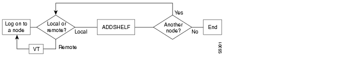
You can add an interface shelf from Cisco WAN Manager or the command line interface (CLI). The steps for adding a new interface shelf to a network are:
Step 1
Step 2
Step 3
illustrates the sequence of using addshelf either locally or remotely to add one or more interface shelves. To delete an interface shelf, use delshelf after you delete connections and the active interfaces. To view status of an interface shelf, execute dspnode at the routing hub. (The dspnw command shows an alarm on a node but does not specify an interface shelf.)
Figure 3-22 Add an Interface Shelf from the Hub
Adding Connections in a Tiered Network through the CLI
Adding a connection in a tiered network requires that you add local segments and a network segment. The following steps illustrate the setup for each segment for an interworking connection:
Step 1
addcon slot.port.DLCI local_nodename slot.vpi1.vci1
where the first slot has a Frame Relay card, and the second slot has a BTM. (In an IGX interface shelf, the only card that supports the trunk to the hub is the BTM.)
Step 2
addcon slot.port.vpi1.vci1 remote_nodename slot.port.vpi2.vci2
where the card in slot is a BNI
Step 3
addcon slot.vpi2.vci2 local_nodename slot.port.DLCI
where the second slot is a Frame Relay card.
Note that the vpi and vci need to match only at the segment on the local interface shelf. Apart from this requirement, the vpi.vci on segment 1 can also be the same as the vci.vpi on segment 2.
Converting a Routing Node to an Interface Shelf
To convert a routing node to an interface shelf, first remove the routing node from the network by deleting all connections then deleting and downing all lines and trunks. Refer to Cisco WAN Manager documentation or the Cisco WAN Switching Command Reference for instructions. In the command reference, check the chapters by topic (ATM connections, Frame Relay connections, trunks, and so on) for the applicable command descriptions. Next, you need to add the node as an interface shelf. Refer to the section "Configuring an IGX Switch to Be an Interface Shelf" section for instructions.

Posted: Thu Nov 11 00:52:44 PST 2004
All contents are Copyright © 1992--2004 Cisco Systems, Inc. All rights reserved.
Important Notices and Privacy Statement.