|
|

Table Of Contents
Common Alarms, Controls, and Indicators
Introduction to the UXM Port Mode
Types of Voice and Data Connections on the UVM
Applicable Commands for the UVM
Universal Voice Interface Back Card (BC-UVI-2T1EC)
Universal Voice Interface Back Card (BC-UVI-2E1EC)
Universal Voice Interface Back Card (BC-UVI-2J1EC)
Channelized Voice Module (CVM)
T1 Interface Back Card (BC-T1)
E1 Interface Back Card (BC-E1)
Maximum Connections Per Port With Signaling Protocols
Frame Relay Over T1 and E1 Lines
Frame Relay Interface (FRI) V.35 Card
Frame Relay Interface for X.21
Y-Cable Redundancy and Port Modes
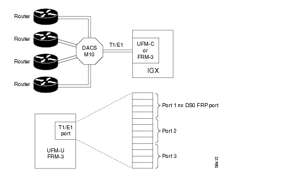
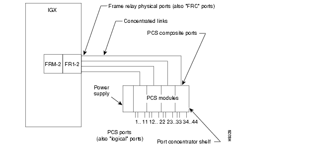
FRM-2 Interface to the Port Concentrator Shelf
Collecting the Monitoring Information
The Cisco Line of Access Devices for WAN Switches
The FastPAD Line of Access Devices
Synchronous Data Interface Card (SDI)
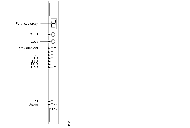
Low Speed Data Interface Card (LDI)
Line Interface Cards
This chapter describes the hardware and related functions for each line card in an IGX node. The description of each card includes:
•
Function
•
•
A brief description of optional peripherals and third-party equipment appears at the end of the chapter. For system specifications, such as protocols and standards, refer to Appendix A.
For all matters relating to installation, troubleshooting, user-commands, and repair and replacement, refer to the Cisco IGX 8400 Series Installation and Configuration publication.
Other manuals that relate to IGX operation are:
•
•
•
Line Card Groups
This chapter introduces each of the following line card groups:
•
•
•
•
List of IGX Cards
lists the front cards that operate in an IGX switch. lists the ATM UNI interface cards, and lists the interface cards for all other transport types that an IGX node supports.
In addition to the native front and back cards, an IGX switch can use existing IPX 16/32 service module cards in conjunction with an Adapter Card Module (ACM). The ACM cards connect to IPX 16/32 front cards and perform the adaptation necessary to allow IPX cards to operate in an IGX node. Note that this IPX upgrade feature cannot utilize IPX 8-specific cards. Beyond this limitation, IPX back cards can operate in an IGX system without modifications.
Table 4-1 Front Cards
Table 4-2 ATM UNI Back Cards
Table 4-3 Voice, Frame Relay, Data, and Access Device Interface Cards
Note
Common Alarms, Controls, and Indicators
Front cards and back cards have faceplates with indicator LEDs and, on some front cards, push-button controls. In addition, back card faceplates have cable connectors. In slots where no back card exists, a blank faceplate must reside to contain Electromagnetic Interference (EMI) and Radio Frequency Interference (RFI) and to ensure correct air flow.
The LED indicators are on the front and back card faceplates. Each plug-in card has both a green Active LED and a red Fail LED at the bottom of the faceplate. In general, the meaning of each LED is indicated in . Some other cards have additional indicators, connectors, or controls, which the appropriate sections describe.
Table 4-4 Common Card Status Indicators
Adapter Cards
Cisco can upgrade IPX service/interface cards for use in an IGX node. This allows the IGX node to provide all the services of the IPX with cards of proven efficiency, functionality, and reliability. The upgrade is available only as a factory upgrade. The factory upgrade consists of an adding one of three possible Adapter Card Modules (ACM) and possible firmware or hardware modifications. Due to the complexity of the ACM, field upgrades of IPX cards are not possible.
Connecting IPX front cards to their corresponding back cards on the IPX requires the use of a utility or local bus. On upgraded IPX cards (IGX cards), the local or utility bus is not necessary.
The following IPX cards can be adapted for use in the IGX node:
•
•
•
•
•
•
•
•
Universal Switching Module
This description of the Universal Switching Module (UXM) covers the following topics:
•
•
•
•
•
•
•
The Universal Switching Module (UXM) can function in one of two modes. In port mode, the UXM serves as either an ATM User-to-Network Interface (UNI) or a Network-to-Network (NNI) interface. In trunk mode, the UXM supports trunks in the network. The back cards support multiple ports operating at OC3/STM-1, T3, E3, T1, or E1 rates.
Note
On the other hand, a "port" is also a layer of logical functionality that applies to port cards as well as trunk cards. For example, whether you activate a line to a router or activate an ATM trunk to the network, you must subsequently configure the logical port in either case.
For a UXM, therefore, the documentation describes a logical "port" on a port-mode UXM for a UNI or NNI at the edge of a network, yet it also refers to a "port on a UXM trunk" as a layer of logic.
Introduction to the UXM Port Mode
The UXM can transport ATM cells to and from the Cellbus at a maximum rate of 310 Mbps in either direction. The UXM can support up to 4000 connections in port mode. A connection on a port can be either a cell-forwarding connection or a complex gateway connection.
The UXM communicates only ATM cells to either the network or the CPE. On the Cellbus, however, the UXM communicates either ATM cells or FastPackets. With another UXM, it communicates only in ATM cells. With other cards, the UXM communicates in FastPackets. Through its gateway functionality, the UXM translates between FastPackets and ATM cells so it can transport voice, data, or Frame Relay traffic that other cards have put in FastPackets.
Determining the UXM's Mode of Operation
The UXM reports the mode of the card to switch software when you first activate either a line to the UNI or NNI side or a trunk to the network. If you activate a line, the UXM goes into port mode. If you activate a trunk, the UXM goes into trunk mode. The command line interface (CLI) commands for these operations are upln and uptrk, respectively. (The UXM description in this chapter lists important information about the commands that apply to the UXM, but the order of their use appears in the Cisco IGX 8400 Series Installation guide. For a detailed description of each command and its parameters, see the Cisco WAN Switching Command Reference.)
Example Networks With UXMs
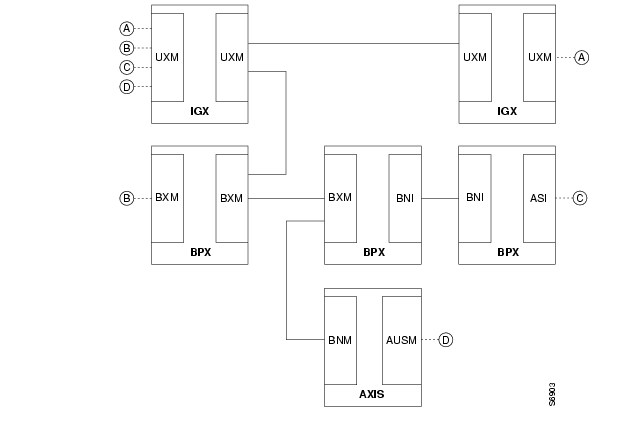
Networks with both trunk mode and port mode UXMs appear in and , respectively. The nodes in use only UXMs for port interfaces and trunk interfaces. shows a variety of cards providing interfaces for different traffic types.
The network carrying only ATM traffic appears in . Each UXM trunk card in connects to either another UXM trunk card or a BXM operating as a trunk. The ATM UNI ports are the UXM port cards (for connection A), the BXM operating in port mode (for connection B), the ASI (for connection C), and the BXM feeder trunk (for connection D). Connection D is a two-segment connection. One segment of connection D exists between the BNM and AUSM on the Cisco MGX 8220 shelf, and the other segment exists between the BXM and the UXM UNI port.
Figure 4-1 UXMs in a Network With Pure ATM Traffic
A network with ATM traffic and FastPacket-based traffic appears in . Connections A and B are ATM connections that terminate on UXM UNI port cards and a BXM operating as a UNI port. Connection C is a Frame Relay connection between a UFM and an FRM. Connection D is a voice connection between a CVM and CDP. Connection E is a local connection between a UFM and a UXM UNI port (thus terminating on the same node). For connections C-E, the gateway function of the UXM packs and unpacks the FastPackets into and out of the ATM cells.
Figure 4-2 UXMs in a Network With Heterogeneous Traffic
UXM Features
The following list broadly identifies the features of the UXM. After the bulleted list, the remaining sections of this introduction contain tables that list the features on particular topics, such as interworking. Actual descriptions of the features appear in the section titled " The UXM in UNI/NNI Port Mode."
•
•
•
•
•
•
•
•
•
•
•
•
•
•
Interfaces for the UXM
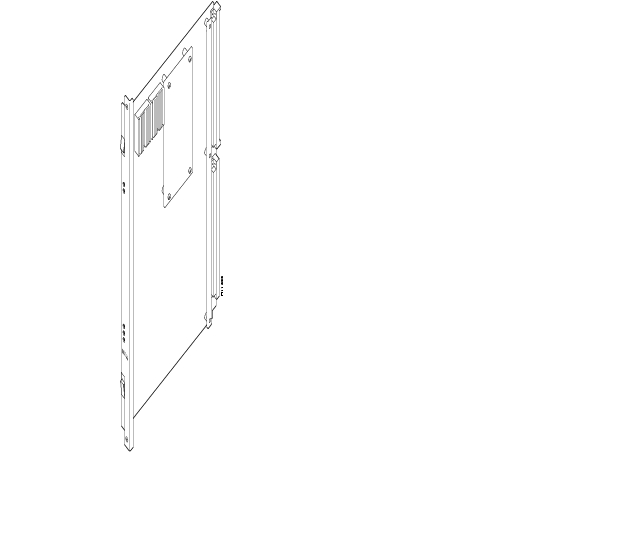
is a list of the UXM back cards. shows the UXM front card. defines all possible combinations for the states of the front card status LEDs (Fail, Active, and Standby).
Table 4-5 Interface Back Cards for the UXM
Figure 4-3 UXM Front Card
Table 4-6 UXM Status LEDs
Maximum Number of UXMs
Switch software limits the number of logical trunks and ports on an IGX switch. The maximum number of UNI or NNI ports in an IGX switch is 64. The maximum number of logical trunks is 32. To determine the number of each logical type in the switch, add the number of ports on multiport cards and single-port cards. These sums cannot exceed 64 ports and 32 trunks. For example, using exclusively 2-port OC3 trunks, you could install:
16 OC3 UXMs=32 trunks / 2 trunks per card
Switch software monitors the number of logical ports and trunks, not the number of UXMs. Therefore, the software keeps you from activating an excessive number of lines or trunks on the node rather than flagging the presence of too many cards.
Y-Cabled UXM Redundancy
The UXM features hot standby as a part of its Y-cable redundancy capability. With hot standby, the redundant card receives the configuration information as soon as you finish specifying redundancy. The standby card also receives updates to its configuration as the active card configuration changes. Hot standby lets the backup card go into operation as soon as necessary rather than waiting for the NPM to download the configuration
Y-cable redundancy requires that both cards are active and available before you set up redundancy. Use Cisco WAN Manager or the CLI commands upln, then addyred. (See also descriptions of addyred, delyred, dspyred, and prtyred in the Cisco WAN Switching Command Reference publication).
Switchover to a Redundant UXM
If the card fails, a switchover occurs to a Y-cabled, redundant UXM card set if available. If the switchover occurs, the primary UXM acquires failed status, and the Fail LED turns on.
Card Mismatch
The UXM supports two types of card mismatch notification. The notification common to all cards occurs when you connect an unsupported back card to the front card. The mismatch notification unique to the UXM occurs if you attach a supported back card but one that has a different interface or a smaller number of the correct line types than what firmware previously reported to software.
The UXM informs switch software of the number and type of interface ports when you first activate the card. Software retains the back card configuration data if you remove a back card. If you subsequently attach a card with fewer ports, switch software flags a mismatch. Replacing a back card with more ports of the same line type or exchanging SMF and MMF OC3 (STM-1) cards is not a mismatch. To change the interface that software has on record, you must first down the card then re-activate it. To read how to down a card, see the Cisco IGX 8400 Series Installation and Configuration publication
Traffic Management Features
is a list of the traffic management features of the UXM.
Table 4-7 Traffic Management Features
The UXM as a Clock Source
A UXM line or trunk can provide the clock for the node. Use the dspclksrcs command to display available clock sources, dspcurclk to show the current clock source, and cnfclksrc to specify a new clock source. To clear clock alarms, use clrclkalm.
Cellbus Bandwidth Usage
The Cellbus consists of four operational lanes plus one backup lane. (The backup lane becomes active if a lane fails.) The FastPacket-based cards can use only one lane and communicate only in FastPackets. If a FastPacket-based card controls the Cellbus, no ATM cells can be on the Cellbus.
When the UXM has control of the Cellbus, it can pass any of the following:
•
•
•
Switch software monitors and computes Cellbus bandwidth requirements for each card in the Cisco 8400-series switches. For the UXM alone, you can change its Cellbus bandwidth allocation. (You cannot view or alter bandwidth allocation for other cards.) The unit of measure for the ATM cell and FastPacket bandwidth on the Cellbus is the universal bandwidth unit (UBU).
Switch software allocates a default number of UBUs for the card when the UXM identifies the back card interface to switch software. If you remove a card, switch software reserves the current Cellbus bandwidth allocation for that card. If, as you add more connections, the load approaches oversubscription, switch software displays a warning message. Regardless of the warning message, Cisco advises you to monitor bandwidth allocation and allocate more UBUs for the card to avoid oversubscription.
For the UXM, switch software allocates enough bandwidth to meet the requirements for the minimum cell rate (MCR) and therefore does not accommodate burstiness. Therefore, you must know the UXM bandwidth requirements to determine if you should change its UBU allocation. Monitor the bandwidth requirements after you build the network and during normal operation. On the CLI, the applicable commands are cnfbusbw and dspbusbw.
You can raise, lower, or check a UXM's UBUs with cnfbusbw. The cnfbusbw privilege level is 0—superuser. To check a UXM's UBUs, use dspbusbw or cnfbusbw. Any user can use dspbusbw. Each command's display provides the information you need to determine if you must increase the UBUs on a particular UXM. The only value you can change is allocated bandwidth. An example display for cnfbusbw appears in Figure 4-4. The card-based default and maximum Cellbus bandwidth for each interface appears in . Note that FastPackets require substantially less Cellbus bandwidth than ATM cells. The FastPacket requirements in the figure and table reflect the restriction of FastPackets to one lane and the maximum processing rate of the gateway on the UXM. The values you can view with the cnfbusbw and dspbusbw commands are:
•
•
•
•
•
Figure 4-4 Example Display for cnfbusbw
sw197 TN StrataCom IGX 16 9.2 Apr. 7 1998 03:15 GMTBus Bandwidth Usage for UXM card in slot 5 Last Updated on 04/07/98 03:15:42FPkts/sec Cells/sec UBUsMinimum Reqd Bandwidth: 0 100100 26Average Used Bandwidth: 0 0 0Peak Used Bandwidth: 0 0 0Maximum Port Bandwidth: - 288000 72Allocated Bandwidth: 1(Cell Only): - 4000(Cell+Fpkt): 2000 3000(Fpkts / 2 + Cells) <= 4000Reserved Bandwidth: - 4000 1This Command: cnfbusbw 5Allocated UBU count:Table 4-8 Cellbus Bandwidth Allocation for UXM Interfaces
Planning for Cellbus Bandwidth Allocation
With the Network Modeling Tool™ (NMT), you can use the projected load for all UXM cards in the network to estimate their Cellbus requirements. During normal operation, you can use Cisco WAN Manager to obtain the trunk and port statistics then decide whether to use cnfbusbw to increase the UBU allocation. If you are using only the CLI, you would need to establish a virtual terminal (vt) session to each node then execute dspbusbw or cnfbusbw.
Calculating Cellbus Bandwidth Changes
To determine how many UBUs are necessary, use the values for average bandwidth used (see Figure 4-4) in the following formula:
In most circumstances, the fps and cps values from average bandwidth used are sufficient. The peak bandwidth used values are primarily informational.
The information in provides the ranges for the interface type. Note that, if you do the math according to the formula, you see that the value in the cells-alone column of equals the result of adding half the FastPacket value to the cell value in the cells plus FastPackets column.
When you use dspbusbw, a yes/no prompt asks if you want firmware to retrieve the usage values. If you enter a "y," the UXM reads—then clears—its registers and thus restarts statistics gathering. If you enter an "n," switch software displays the current values that reside in control card memory (on the NPM). The values in memory come from the last update from the UXM.
ATM Across a Public ATM Network
The UXM can support trunking across a public ATM network such that virtual channel connections (VCCs) traverse a single virtual path trunk. This feature lets you map multiple trunks to a single port of a UNI. The UNI connects to either a public or private ATM network. The virtual trunk package is a lower-cost alternative to leased circuits but still has the full set of Cisco ATM traffic management capabilities. This application requires two UXMs and a clock from an external source. The rates can be OC-3/STM-1, T3/E3, or T1/E1.
Figure 4-5 UXMs Configured for a Public ATM Network
Note the following characteristics of this form of trunking across a public network:
•
•
•
Refer to as you read the steps for the following example set-up:
Step 1
•
•
•
•
Step 2
Step 3
The UXM in UNI/NNI Port Mode
In port mode, the UXM can support up to 4000 virtual circuit (VC) or virtual path (VP) ATM connections and can operate as either an NNI or a UNI. The connections can be either ATM connections or FastPacket-based (gateway). A "gateway" connection requires the UXM to translate between FastPackets and ATM cells. For ATM cell-based traffic, no conversion takes place: only ATM cells in the ingress and egress directions traverse the Cellbus between the UXM port card and UXM trunk card.
Gateway connections are a class of resource for the UXM. When you add connections, the outcome of the routing process may reduce the number of available gateway connections. The forthcoming section " Routing Over Cell Trunks Only" describes the effect of route selection on this resource.
Operating in port mode, the UXM provides an interface for the following classes of ATM service: CBR, VBR, standard ABR with and without virtual source/virtual destination (VS/VD), ABR with ForeSight, and UBR. The connections on a port-mode UXM—including interworked and cell-forwarded connections—can terminate on the following endpoints:
•
•
•
•
•
•
•
•
Supported Connection Types
The cards that serve as connection endpoints determine the possible types of connections. shows the possible connection type according to the endpoints. In , VC connection is a virtual channel connection; VP connection is a virtual path connection; and ABRFST is ABR with ForeSight. Note that the cards at both ends of a connection must support VS/VD for you to add an ABR connection with VS/VD. For more detailed information on the connection types, refer to the ATM connection description in the Cisco System Overview or the description of the addcon command in the "ATM Connections" chapter of the Cisco WAN Switching Command Reference.
Table 4-9 ATM Endpoints and Connection Types
Routing Over Cell Trunks Only
You can specify trunk cell routing only as an option when you add a connection between UXM, ASI, or BXM ports. When you enable trunk cell routing, switch software routes across only the cell-based trunk cards BNI, BXM, and UXM: no conversion to FastPackets occurs on the route. If you disable trunk cell routing, the routing process may select a FastPacket-based trunk and so decrement the number of available gateway connections. Also, using a FastPacket-based trunk may result in increased network delays. Therefore, enabling trunk cell routing is the preferred choice when you add a connection at a BNI, BXM, or UXM.
If you add connections at other port cards, such as a UFM or ALM/A, switch software does not display the trunk cell routing option.
On the CLI, the addcon prompt for this option appears as "trunk cell routing restrict y/n?" It appears after you enter either the ATM class of service or after you finish specifying all the individual bandwidth parameters that apply to the current connection type. You can specify whether the default for trunk cell routing is "Yes" or "No" through the cnfnodeparm (superuser) command.
Activation and Configuration of a UXM in Port Mode
When you insert a new UXM into the backplane or apply power to the node, the UXM reports the card type and number of lines on the back card. Switch software can then determine the allowed range and characteristics of logical and physical parameters for you to configure. Software thus prevents you from exceeding the maximum number of logical ports on the switch as you activate logical lines through either Cisco WAN Manager or the upln command on the CLI. Applicable, line-specific commands are upln, dnln, cnfln, dsplns, prtlns, and dsplncnf.
shows the line characteristics you can configure for each interface type through either Cisco WAN Manager or the cnfln command on the CLI. also shows the fixed parameters.
Table 4-10 Configurable Line Characteristics
Port Activation and Characteristics
You can activate and configure logical ports as well as configure port queues through Cisco WAN Manager or the CLI. Software prevents you from activating over 64 ports. After activating a port, you can specify a UNI or NNI cell header and optionally specify LMI or ILMI protocol. The CLI commands are upport, dnport, cnfport, cnfportq, dspport, dspports, dspportq, and cnfabrparm.
You can specify the depths as well as high and low thresholds for the CBR, VBR, and ABR queues. (UBR service shares the ABR queue.) You can configure all queues to have the maximum queue size. If congestion occurs, firmware scales down the maximum queue size on the active ports. The maximum size for each queue for the ingress and egress directions is 64000 cells each, so the total for the logical ports on a card is 128000 cells.
For ABR queues, additional parameters are available through Cisco WAN Manager or the cnfabrparm command. The additional parameters are Ingress/Egress Congestion Information (CI) Control and Egress Explicit Rate Stamping (ER). The settings apply to all ports. With CI Control enabled, the CI bit in each resource management (RM) cell in the queue is set if the EFCI threshold is exceeded. If you enable ABR ER, the cell rate for the ABR connection is placed in each of the RM cells.
Summary Statistics
On the CLI, you can specify summary statistics for a UXM port.
With the dspportstats command, you can specify:
•
•
•
•
With the dspchstats command, you can specify:
•
•
•
•
•
•
•
Statistics Commands for Troubleshooting
You can configure bucket statistics through Cisco WAN Manager for logical lines, ports, and channels (connections). Statistics configuration in Cisco WAN Manager requires the TFTP mechanism. You can also enter commands on the CLI. Refer to the Cisco WAN Switching Command Reference publication and the Cisco SuperUser Command Reference publication for descriptions of the following commands:
•
•
•
Integrated and Statistical Line Alarms
Integrated alarms for the UXM consist of LOS, LOF, AIS, YEL, LOC, LOP, Path AIS, Path YEL, Path Trace, and Section alarms. The display for the dsplns command lists an alarm if the related event occurs. You can configure the event duration that qualifies and clears an alarm with cnflnparm.
You can configure the class, rate, and duration for setting and clearing of statistical alarms with the cnflnalm command. Refer to the description of cnflnalm in the Cisco WAN Switching Command Reference publication for a list of all possible line alarm types. The display for the dsplnerrs command shows data for existing alarms. To clear the statistical alarms on a line, use the clrlnalm command.
Loopback and Test Commands
The UXM supports local and remote loopbacks. You can establish a local loopback on either a connection or a port. Remote loopbacks are available for connections only. No line loopbacks are available for the UXM.
UXM Interface Cards
This section provides basic information on the interface back cards for the UXM. The information consists of a general description, an illustration of the card faceplate, and a table describing the connectors and status LEDs. For details on the line technology of each type of interface, see the appendix titled " System Specifications".
Note
The model numbers of the back cards and the order of their appearance are:
•
•
•
•
•
•
•
•
•
•
•
•
•
•
OC-3/STM-1 Back Cards
The OC3/STM-1 back cards for the UXM have the single-mode fiber (SMF) and multi-mode fiber (MMF) connections. The cards are:
•
•
•
•
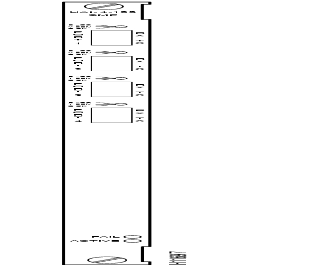
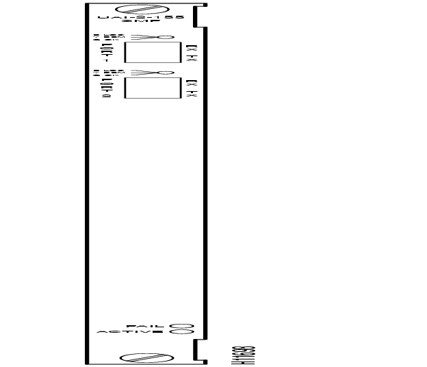
As indicated by the "2" or the "4" in the model number, these cards have two or four transmit and receive connectors. Each line has a tri-color LED whose color indicates its status. Each card also has a red Fail LED and a green Active LED to indicate the status of the card. lists the connectors and LEDs. shows the four-port OC3/STM-1 card. The SMF, EL, and MMF versions appear the same. shows the two-port OC3/STM-1 card. For technical data on OC3/STM-1 lines, see the appendix titled "System Specifications."
Table 4-11 Connectors and LEDs for SMF and MMF Back Cards
Figure 4-6 BC-UAI-4-155-SMF Faceplate
Figure 4-7 BC-UAI-2-155-SMF Faceplate
T3 Back Cards
The T3 back cards for the UXM are BC-UAI-6-T3 and BC-UAI-3-T3. These cards have six and three pairs of SMB connectors, respectively. Each port has a tri-color LED whose color indicates its status. Each card also has a red Fail LED and a green Active LED to indicate the status of the card. lists the connectors and LEDs. shows the six-port T3 card. shows the three-port T3 card. For technical data on T3 lines, see the appendix titled "System Specifications".
Table 4-12 Connectors and LEDs for BC-UAI-6-T3 and BC-UAI-3-T3
Figure 4-8 BC-UAI-6-T3 Faceplate
Figure 4-9 BC-UAI-3-T3 Faceplate
E3 Back Cards
The E3 back cards for the UXM are the six-port BC-UAI-6-E3 and the three-port BC-UAI-3-E3. These cards have six and three pairs of connectors, respectively. Each line has a tri-color LED whose color indicates its status. Each card also has a red Fail LED and a green Active LED to indicate the status of the card. lists the connectors and LEDs. shows the six-port card. shows the three-port card. For technical data on E3 lines, see the appendix titled "System Specifications".
Table 4-13 Connectors and LEDs for BC-UAI-6-E3 and BC-UAI-3-E3
Figure 4-10 BC-UAI-6-E3 Faceplate
Figure 4-11 BC-UAI-3-E3 Faceplate
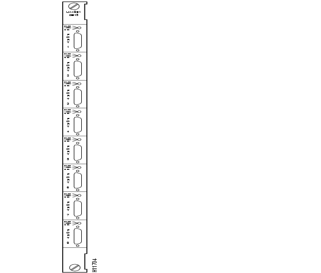
T1 Back Cards
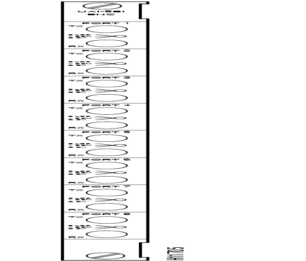
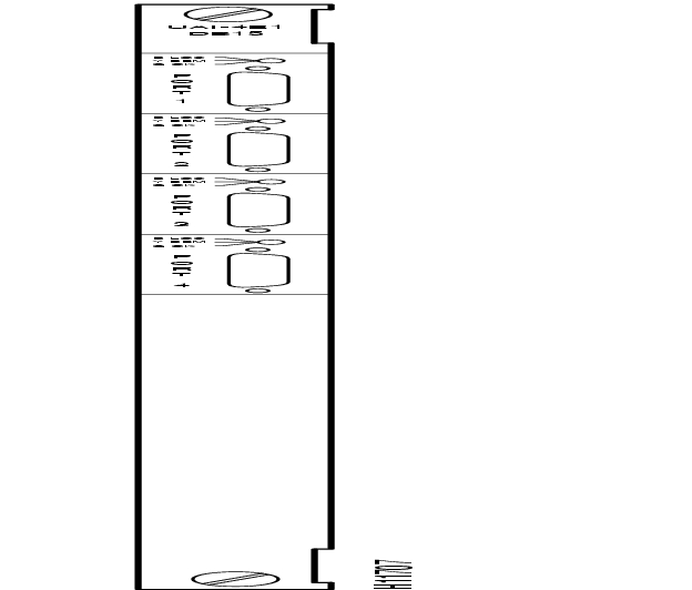
The T1 back cards for the UXM are BC-UAI-8-T1 and BC-UAI-4-T1. These cards have eight and four DB15 lines, respectively. Each line has a tri-color LED whose color indicates its status. If a card failure occurs, all the LEDs turn red. lists the connectors and LEDs. shows the eight-port T1 card. shows the four-port T1 card. For technical data on T1 lines, see the appendix titled "System Specifications".
Table 4-14 Connectors and LEDs for BC-UAI-8-T1 and BC-UAI-4-T1
Figure 4-12 BC-UAI-8-T1 Faceplate
Figure 4-13 BC-UAI-4-T1 Faceplate
E1 Back Cards
The E1 back cards for the UXM are:
•
•
•
•
As the model numbers indicate, the eight and four-port E1 cards can have either BNC or DB15 connectors. Each line has a tri-color LED whose color indicates its status. If a card failure occurs on the back card, all LEDs turn red. lists the connectors and LEDs. shows the eight-port E1 card. shows the four-port T1 card. For technical data on E1 lines, see the appendix titled "System Specifications".
Table 4-15 Connectors and LEDs for BC-UAI-8-E1 and BC-UAI-4-E1
Figure 4-14 BC-UAI-8-E1 DB15 Faceplate
Figure 4-15 BC-UAI-8-E1 BNC Faceplate
Figure 4-16 BC-UAI-4-E1 DB15 Faceplate
Figure 4-17 BC-UAI-4-E1 BNC Faceplate
ATM Line Module A
The ATM Line Module A (ALM/A) provides an ATM UNI port that allows devices such as routers or ATM switches to support VPCs and VCCs across the IGX node. The ALM/A operates as a cell relay interface that supports basic connectivity to IGX interfaces or BPX ASI interfaces through a Cisco WAN switch network. The ALM/A supports ATM connections that terminate at either ATM or Frame Relay endpoints. With the processing that the IGX node provides, cells can cross either an ATM trunk or a FastPacket trunk. This ALM/A description covers the following topics:
•
•
•
•
•
Using the addcon command, you can add connections between the following endpoints
•
•
•
•
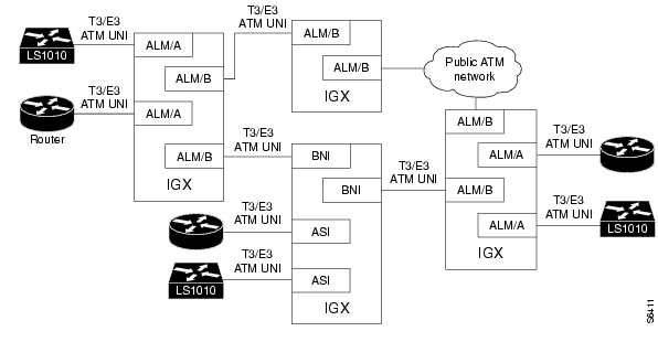
shows an example of a network using ALMs. The network contains connections from an ALM/A to another ALM/A, a UFM, and an ASI. The dashed lines show virtual connections. The solid lines between the trunk cards and the ATM cloud are trunks.
Figure 4-18 ALMs in a Network
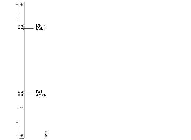
Figure 4-19 ALM/A Faceplate
ALM/A Features
A general list of ALM/A characteristics follows. (Subsequent sections have more particular information on interworking, traffic management, and back cards.)
•
•
•
•
•
•
•
•
•
•
•
•
Connection Types
The ALM/A supports CBR, VBR, ATFR, ATFT, and ATFX connection types. Thus, the card supports ATM, cell forwarding, and both network and service interworking connections. shows the card combinations and connections types. The Cisco IGX 8400 Series Installation manual describes where and when to specify the connection type. For more information on the interworking connections, see the System Manual and the addcon description for Frame Relay and ATM connections in the Cisco WAN Switching Command Reference.
Table 4-16 ALM/A Connection Types
ALM/A
VBR, CBR, ATFR, ATFT, ATFX
UFM
ATFR, ATFT, ATFX
FRM
ATFR
ASI
VCCs only: VBR, CBR, ATFT, ATFR
Traffic Management
The ALM/A uses per-VC queue thresholds and credit-based servicing to control the ingress flow of data to the network and guarantee card resources for each connection.
Using addcon for an ATM or cell-forwarding connection, you specify the VC queue depth and the rate for the connection. If you do not specify a queue depth, the system calculates the queue depth for the connection based on the cell rate. The connection rate determines the service credits. If 80% of the VC queue depth is exceeded, cells with CLP=1 are discarded. If a connection's VC queue is full and the cell rate is exceeded long enough, cells are discarded from the affected queue. Therefore, if a high level of bursty traffic expected for given cell rate, specify a deeper queue for a connection.
For cell forwarding connections, you can explicitly assign VC queue depth for each connection. For ATFR connections, you can assign a VC queue depth by choosing or modifying a Frame Relay class and specifying the queue depth in bytes. Either way, you can over-subscribe the buffer pool on the card. Actually, buffers are dynamically assigned to VC queues as cells arrive and depart. In this scheme, no data is lost unless you over-subscribe and all buffers are occupied. If you do not specify VC queue depth when adding a connection, switch software assigns a percentage of buffers equal to the connection's cell rate divided by the total ALM/A bandwidth. With this approach, over-subscription is not a problem.
ALM/A Operational Parameters
The ALM/A has the following operational parameters:
•
•
•
•
•
•
•
•
•
•
Back Cards for the ALM/A
The ALM/A T3 and E3 back cards are the BC-UAI-1T3 and BC-UAI-1E3, respectively. Each back card has two BNC connectors and six LED indicators. For the BC-UAI-1T3 faceplate items, refer to and . For the BC-UAI-1E3 faceplate items, refer to and . As you read from the top-down, the items in the figure and table correlate to each other. For technical specifications on T3 and E3 lines, refer to the appendix titled "System Specifications".
Table 4-17 BC-UAI-1T3 Connections and Indicators
Figure 4-20 BC-UAI-1T3 Faceplate
Figure 4-21 BC-UAI-1E3 Faceplate
Table 4-18 BC-UAI-1E3 Connections and Indicators
Universal Voice Module
This section describes the Universal Voice Module (UVM) and its interface cards, as follows:
•
•
•
•
•
•
•
•
•
•
•
•
•
•
•
•
•
For installation and configuration instructions, see the Cisco IGX 8400 Series Installation and Configuration publication.
Introduction to the UVM
The UVM card set is a multi-purpose module capable of supporting channelized T1, E1, or J1 lines for carrying voice, data, or both these types of traffic. The voice coding that the UVM supports are:
•
•
•
•
G.729 and G.729A are two versions of CSACELP. G.729A is simpler and can permit a greater number of channels on a UVM. On the other hand, it does not support certain features, such as FAX relay. The applicability of G.729 or G.729A appears as needed throughout this UVM description. The text frequently distinguishes connection types by referring to the standard.
A UVM can terminate connections to a:
•
•
•
•
•
UVM Feature Descriptions
The sections that follow (up to the descriptions of the UVM faceplates) describe the UVM features.
UVM Feature List
The features of the UVM are:
•
•
•
•
•
•
•
•
•
•
•
•
•
•
•
•
•
•
•
•
•
•
•
•
For voice connections that use PCM, ADPCM, or G.729A, the UVM can operate in either 24-channel mode (T1) or 30-channel mode (E1 or J1). If the compression is LDCELP or G.729 CSACELP, the UVM supports up to 16 channels. If more than 16 channels on a T1, E1, or J1 line are to carry traffic with G.729 or LDCELP, the UVM must pass the remaining DS0s on to an second, adjacent UVM for processing. The name of this setup is pass-through.
When a configuration requires pass-through, one UVM port connects to user-equipment, and the other port connects to another UVM. For a description of this feature, see " Channel Pass-Through."
Note
Types of Voice and Data Connections on the UVM
A brief description of each type of voice and data connection appears in . To specify the connections, use either Cisco WAN Manager or the CLI. The CLI command is addcon.
Table 4-19 Types of UVM Connections
Note
The "t,", "td," and "n x 64" connections carry signalling or user-data. All other types carry voice. You can configure any of the voice connections for FAX or modem upgrade.
Standard-rate (64 Kbps) voice connections terminate on CVM or UVM cards. The CVM can terminate a connection from a UVM only if the connection does not use LDCELP or CSACELP. You can specify voice compression through the addcon command and specify echo-cancelling. Through Cisco WAN Manager or by using cnfchec on the CLI, you can select voice compression of 64 Kbps (no compression), 32 Kbps (2:1 compression), 24 Kbps (3:1 compression), 16 Kbps with LDCELP (4:1 compression), or 8 Kbps with CSACELP (8:1). To specify A-law or m-law encoding, use cnfln.
Applicable Commands for the UVM
This section contains a list of the standard commands and the superuser commands you can use on the CLI for voice and data connections on the UVM. lists the standard commands. lists the superuser commands. For details on command syntax and parameters, refer to the Cisco WAN Switching Command Reference publication and the Cisco WAN Switching SuperUser Command Reference publication. Note that the superuser commands have infrequent use, and many of them are strictly for debug purposes.
Table 4-20 Standard User Commands for UVM
Table 4-21 SuperUser Commands for the UVM
Channel Pass-Through
Pass-through is a setup in which two, locally connected UVMs support the maximum number of channels on a T1, E1, or J1 line.
Note
A single UVM can support mixed connection types and compression algorithms. For example, you can add a combination of ADPCM, LDCELP, or CSACELP connections. Any combination is possible if the configuration does not exceed the capacity of the card.
The maximum number of channels that can use G.728 (LDCELP) or G.729 compression is 16, so not all possible channels on a line are used if they are using LDCELP or G.729 CSACELP. To use all possible channels on a line with these compression types, you must configure pass-through by using a second UVM. Pass-through, for example, lets a PBX trunk use all of its bandwidth when the only compression is LDCELP or G.729 CSACELP.
In the pass-through scheme, a primary UVM connects through a cable to a secondary UVM. The primary UVM passes the unprocessed channels to the secondary UVM. Pass-through applies to LDCELP or G.729 CSACELP. The G.729A version CSACELP does not require pass-through because one UVM can support all the channels on a line.
You can configure pass-through by using Cisco WAN Manager or the command line interface (CLI). The CLI command for specifying pass-through is cnflnpass. For a description of how to set up pass-through, refer to the Cisco IGX 8400 Series Installation and Configuration publication. For a detailed description of the cnflnpass command, refer to the Cisco WAN Switching Command Reference publication.
When you are setting up pass-through, switch software does not allow you to duplicate the channel numbers once you have added the channels to the primary UVM. With UVMs in slots 7 and 8, for example, if you add 16 channels with LDCELP to the primary UVM in slot 7 (7.1.1-16), the system prevents you from adding channels 8.1.1-8. Instead, you would add 8.1.17-24.
Note
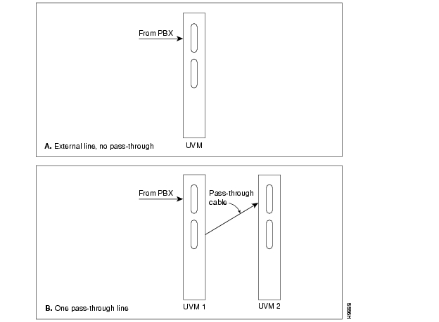
The possible arrangements for E1 or J1 lines appear in . It shows:
•
•
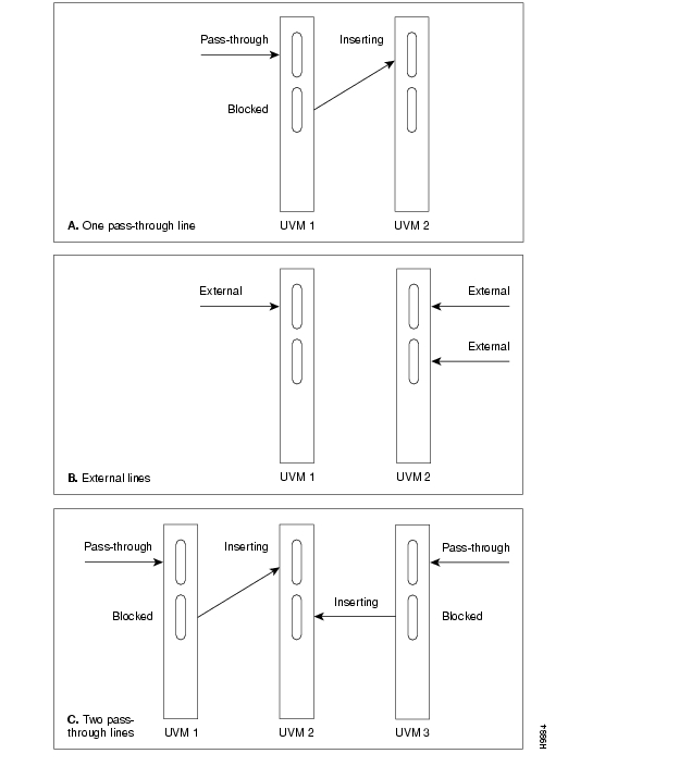
The three possible arrangements of UVMs with T1 lines appear in . It shows:
•
•
•
Figure 4-22 Pass-through and non pass-through modes for E1 or J1
Figure 4-23 Pass-through and non pass-through modes for T1
UVM Data Operation
The UVM supports standard, 64-Kbps data connections and super-rate (n x 64) data connections. Data connections can terminate on a CVM or a UVM. The super-rate connections can support an aggregate of up to eight, 64-Kbps channels—frequently used for video. These super-rate channels should be contiguous or, if necessary, alternating.
Signaling on the UVM
The UVM extracts information from the CAS signaling bits in the T1, E1, or J1 frame. When a signaling bit changes state, the UVM sends signaling packets to the card at the other end of the connection. CSS signaling, such as DPNSS and ISDN signaling, are supported through a clear (transparent) channel. The supported combinations of signaling and line configurations are:
•
•
•
•
In addition to the preceding, the UVM can set, invert, and clear AB or ABAB bits (T1) or ABCD bits (for E1 or J1) to accommodate some signaling conversions.
On the CLI, use cnfln to specify the signaling and dsplncnf to see the signaling configuration.
Up to 23 voice interface types, such as 2-W E&M, FXO/FXS, or DPO/DPS, can be selected from a template to condition the VF signaling. You can also customize the signal conditioning. Refer to the descriptions for the cnfcond and cnfvchtp commands in the Cisco WAN Switching Command Reference for details. You can program voice channel signaling for any of the following:
•
•
•
•
FAX Relay
The FAX relay feature compresses the DS0 bit stream of a G3 FAX (9.6 Kbps) connection to 9.6 Kbps for transport through the network. (If the bit stream for the FAX is lower, the UVM compresses it to that lower rate.) The UVM supports FAX relay for LDCELP and G.729 (but not G.729A) connections. Interworked connections between an IGX node and Cisco 3810 access device can also carry FAX relay data.
You can specify FAX relay by using the cnfchfax command. The maximum number of FAX relay channels on a UVM is 16. Once you have enabled it, FAX relay overrides the automatic FAX upgrade feature—but a data modem still upgrades to PCM or ADPCM. (The automatic upgrade feature suspends compression when a modem or FAX tone appears on a voice connection.)
Loopbacks on the UVM Card Set
You can set up local and remote loopbacks to check UVM-terminated connections. A local loopback functions at the system bus interface. It returns data and supervision back to the local facility to test the local UVM card set and the customer connection. Remote loopbacks extend to the UVM card at the far-end and check both transmission directions and much of the far-end UVM. For descriptions of the commands that support loopbacks, refer to the Cisco WAN Switching Command Reference.
Line Statistics
The UVM card set monitors and reports statistics on the following input line conditions:
•
•
•
•
•
•
•
•
•
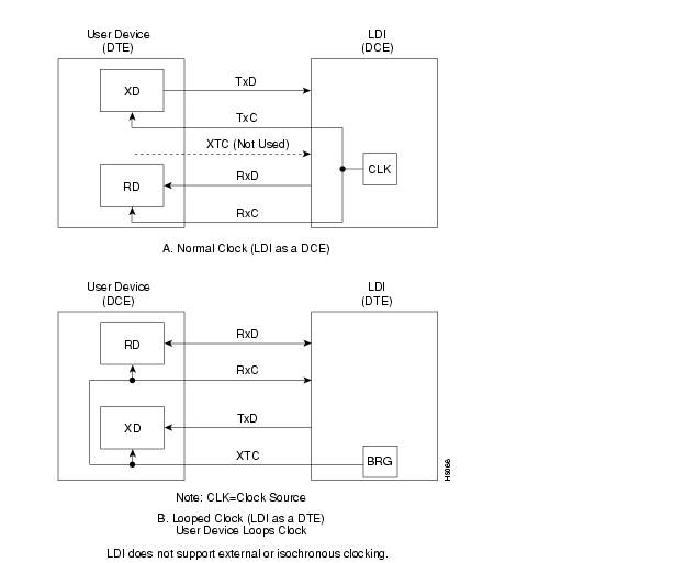
Clock Modes
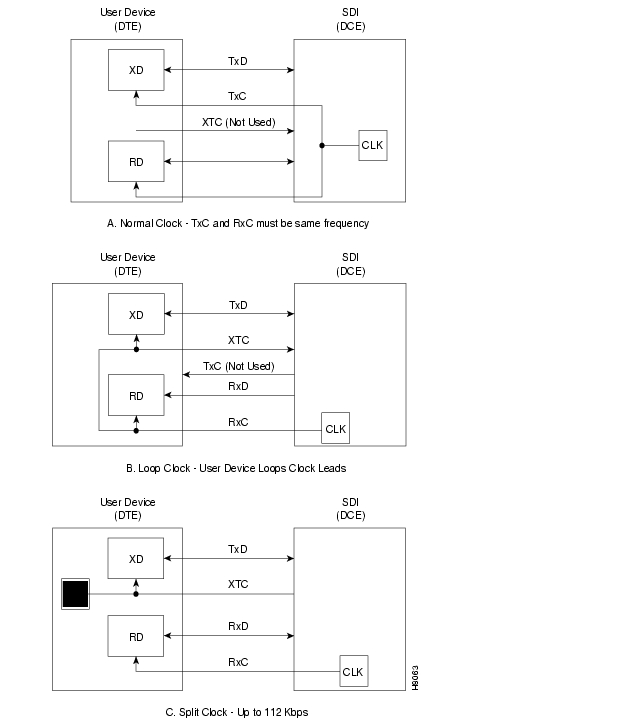
The back cards support two clock modes. You select the mode through software control (cnfln on the CLI). The clock modes are normal clocking and loop timing.
With normal clocking, the UVM supplies the transmit clock for outgoing data (towards the CPE).
With loop timing, the UVM uses the receive clock from the line for the incoming data and redirects this receive clock to synchronize the transmit data.
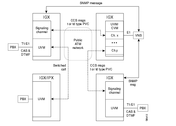
CAS Switching
The UVM supports CAS for Voice Network Switching (VNS) by converting CAS signaling and DTMF tones to CCS call-control messages. These signal conversions let the VNS unit route calls from a PBX over a WAN. For setup instructions, see the VNS documentation and the Cisco WAN Switching Command Reference publication.
The converted CCS messages for all channels on the line travel on a regular t-type or a special td-type PVC connection from the UVM to another UVM card. The VNS device can receive the CCS messages from t-type or td-type PVC connections on the signaling channel of CAS-switching UVM cards in the network.
When the VNS unit receives a CCS call-control message, it determines the destination from the control message and issues SNMP commands to add a connection from a channel on the CAS switching line to the destination across the network. CAS-switching in a network appears in .
Figure 4-24 CAS-Switching
Restrictions to CAS-Switching on the UVM
The limitations on CAS-switching with Model C or Model D firmware are:
•
•
•
•
•
•
Refer to VNS documentation for a full description of this product.
D-Channel Compression
D-channel compression applies to the Cisco Voice Network Switching (VNS). The minimum VNS release is 3.1. This feature compresses the signaling traffic between the application UVM and the network (VNS) UVM. D-channel compression reduces the consumed bandwidth from 64 Kbps per VNS signaling channel to 16 Kbps or less. It applies to CCS lines or CAS lines that where the CAS-switching feature is operating.
D-channel compression switches on when you add the signaling connection through Cisco WAN Manager or by using the addcon command on the CLI. To turn on D-channel compression, specify the connection type as "td." The maximum number of "td" connections on a UVM is 32.
Voice SVC Caching
The UVM supports a feature that accelerates call setup and teardown for frequently used channels. The feature is voice SVC caching. It works in conjunction with VNS. The only consideration for the UVM is that you must configure each line to accommodate voice SVC caching.
On the CLI, use the cnfln command to enable this feature on the line and dsplncnf to see the configuration. If you configure a line for voice SVC caching, you can still add standard voice connections on that line. Note that you cannot enable SVC caching on pass-through lines.
For a more detailed description of voice SVC caching, refer to the VNS documentation.
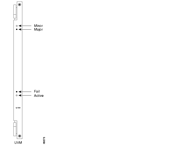
UVM Front Card Faceplate
and describe the UVM front card faceplate.
Table 4-22 UVM Faceplate Indicators
Figure 4-25 UVM Front Card Faceplate
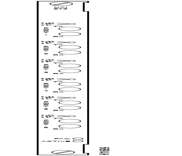
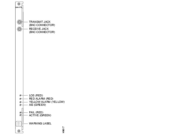
Universal Voice Interface Back Card (BC-UVI-2T1EC)
The BC-UVI-2T1EC back card provides two T1 line interfaces for a UVM card. The features of the BC-UVI-2T1EC are:
•
•
•
•
•
•
B8ZS supports clear channel operation because B8ZS eliminates the possibility of a long string of 0s. B8ZS is preferable whenever available.
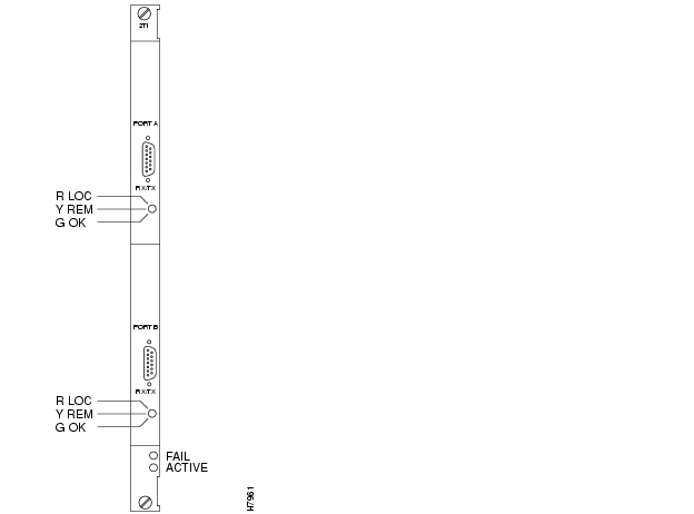
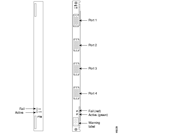
and provide information on the faceplate of the BC-UVI-2T1EC. When you correlate the descriptions in the table with the callouts in the figure, read from the top of the table to the bottom. The standard port connector is a female DB15.
Figure 4-26 BC-UVI-2T1EC Faceplate
Table 4-23 BC-UVI-2T1EC Connections and Status LEDs
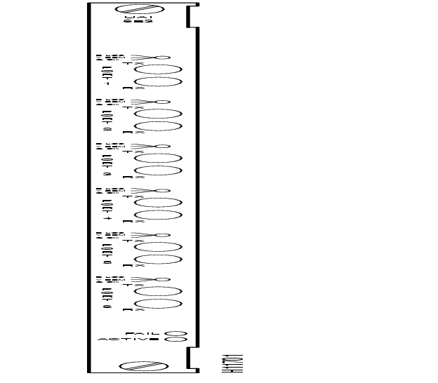
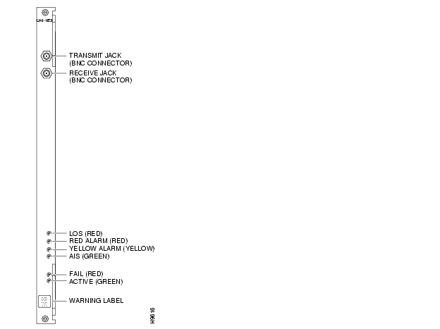
Universal Voice Interface Back Card (BC-UVI-2E1EC)
The BC-UVI-2E1EC back card provides an E1 circuit line interface for a UVM. The BC-UVI-2E1EC provides the following features:
•
•
•
•
•
•
•
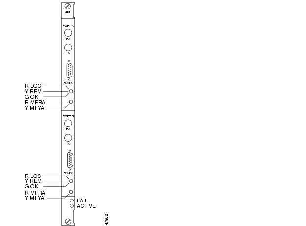
shows and lists status LEDs and connections on the BC-UVI-2E1EC faceplate. When you correlate the table and figure items, read from the top to the bottom.
Figure 4-27 BC-UVI-2E1EC Faceplate
Table 4-24 BC-UVI-2E1EC Connections and Status LEDs
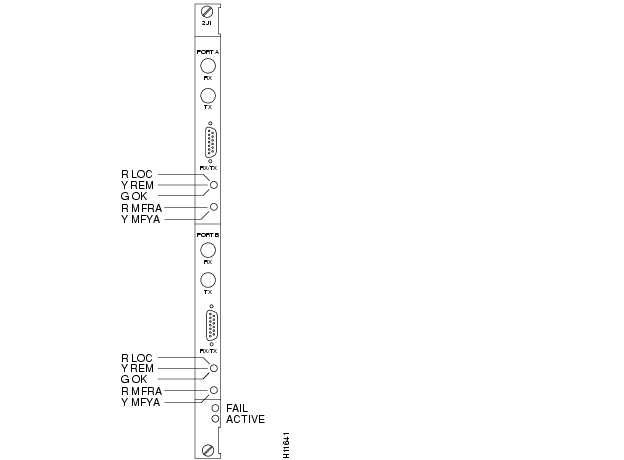
Universal Voice Interface Back Card (BC-UVI-2J1EC)
The BC-UVI-2J1EC back card provides a J1 line interface for a UVM card. The BC-UVI-2J1EC does the following:
•
•
•
•
•
•
•
•
shows and lists status LEDs and connections on the BC-UVI-2J1EC faceplate. When you correlate the table and figure items, read from the top to the bottom.
Figure 4-28 BC-UVI-2J1EC Faceplate
Table 4-25 BC-UVI-2J1EC Connections and Status LEDs
Channelized Voice Module (CVM)
This section introduces the Channelized Voice Module (CVM) and its related back cards. The topics covered in this section are as follows:
•
•
•
•
•
•
•
•
For setup instructions, see the Cisco IGX 8400 Series Installation and Configuration publication and the relevant commands in the Cisco WAN Switching Command Reference publication (the voice-specific commands are in the chapter titled "Voice Connections").
Introduction to the CVM
The CVM is a multi-purpose front card. A CVM circuit line can carry the following types of traffic:
•
•
•
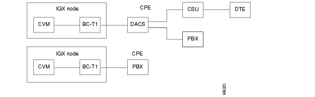
The default mode for a channel on a CVM is voice. In addition to other CVMs, a CVM can communicate with a CDP in an IPX or one of the ports on a UVM. illustrates different traffic configurations. You can use the CVM in either 24-channel mode (T1) or 30-channel mode (E1). You assign the circuits on a CVM hop on a per-timeslot basis within a T1 or E1 frame.
The CVM cards can reside in any non-reserved slot in an IGX node. The front card operates with either a BC-T1, BC-E1, or BC-J1 back card. For details on back cards, see the forthcoming sections titled " T1 Interface Back Card (BC-T1)," " E1 Interface Back Card (BC-E1)," or " BC-J1 Description".
Figure 4-29 CVM Application Diagram
CVM Features
The following is a list of CVM features.
•
•
•
•
•
•
•
•
•
•
•
•
•
•
•
•
Note
Modes of CVM Operation
This section describes the operational parameters you can specify for the CVM card set. is a list of the types of CVM operation. The sections that follow further describe the listed subjects.
The first two entries in are the two types of 64-Kbps operation. The "p" indicates uncompressed PCM voice. The "t" indicates 64 Kbps clear channel data. The table then shows voice and data modes, transmit/receive rates, and indications of compression and ZCS (zero code suppression). A "c" or an "a" preceding a numerical value indicates compression. A "c" indicates compression with voice activity detection (VAD), so "c" does not apply to data connections. An "a" indicates compression without VAD. The "a" can apply to either voice or data. The numerical value following the "a" or "c" is the bit rate. also explains the significance of the other characters that may follow the bit rate.
Standard-rate (64 Kbps) voice connections terminate on CVM or UVM T1 or E1 lines. (The CVM can terminate a connection from a UVM only if the connection does not use LDCELP.) You can configure the voice compression, and echo cancelling for each channel, and—when circumstances make it appropriate—A-law or m-law encoding. You can select voice frequency compression of 64 Kbps (no compression), 32 Kbps (2:1), 24 Kbps (3:1), or 16 Kbps (4:1). The compression ratios approximately double when you also enable the internal VAD.
Table 4-26 Types of CVM Connections
CVM Voice Operation
The particular voice features are:
•
•
•
•
•
In addition to the preceding, the CVM can set, invert, and clear AB or ABAB bits (T1) or ABCD bits (E1) to accommodate some signaling conversions.
CVM Data Operation
A CVM can provide data connections to the network. Data connections that originate on a CVM can terminate on a CVM, UVM, HDM, or LDM in an IGX switch. In an IPX switch, data connections that originated on a CVM can terminate on a CDP, SDP, or LDP.
Two categories of data connections exist on the CVM. The categories are super-rate and subrate. A super-rate connection is an aggregate of DS0s. A super-rate connection can consist of any combination of 56 or 64 Kbps-connections up to a maximum of 8 DS0s. The channels must be contiguous or alternating. The 56-Kbps channels are bit-stuffed up to 64 Kbps on the line. The CVM removes the bits prior to packetization. Note that super-rate connections carry no supervisory bits.
A subrate data connection has a rate less than 64 Kbps and exists within a DS0. Supported rates are 2.4, 4.8, 9.6, and 56 Kbps. The type of subrate data connection that Cisco supports is DS0A. In-band DS0A link codes are translated into EIA control lead states for HDM or LDM-to-CVM connections. Fast EIA, Repetitive Pattern Suppression (RPS), and isochronous clocking are not available.
Signaling on the CVM
The CVM extracts information from the signaling bits in the E1 or T1 frame. When a signaling bit changes state, the CVM generates signaling packets to the CVM at the other end of the connection. DPNSS and ISDN signaling are supported through a clear channel (transparent mode). The supported combinations of signaling and line configurations are as follows:
•
•
•
•
Up to 23 voice interface types, such as 2-W E&M, FXO/FXS, or DPO/DPS, can be selected from a template to condition the VF signaling. You can also specify customized signal conditioning. Voice channel signaling is programmable for any of the following:
•
•
•
•
Voice SVC Caching
The CVM supports a feature that accelerates call setup and teardown for frequently used channels. The feature is voice SVC caching. It works in conjunction with VNS. The only consideration for the CVM is that you must configure the line to accommodate voice SVC caching. On the CLI, use the cnfln command to configure the line for this feature and dsplncnf to see the configuration. If you configure a line for voice SVC caching, you can still add standard voice connections on that line. For a more detailed description of voice SVC caching, refer to the VNS documentation.
Line Statistics
The CVM card set monitors and reports statistics on the following input line conditions:
•
•
•
•
•
•
•
•
•
On the CLI, use cnfln to specify the signaling and dsplncnf to see the signaling configuration.
Loopbacks on the CVM Card Set
You can set up local and remote loopbacks to check CVM-terminated connections. A local loopback functions at the system bus interface. It returns data and supervision back to the local facility to test the local CVM card set and the customer connection. Remote loopbacks extend to the CVM card at the other end and check both transmission directions and much of the far-end CVM.
CVM Faceplate Description
The CVM faceplate has four LED indicators: Active, Fail, Major, and Minor (see ). The label on the faceplate also shows the type of CVM card.
Table 4-27 CVM Faceplate Indicators
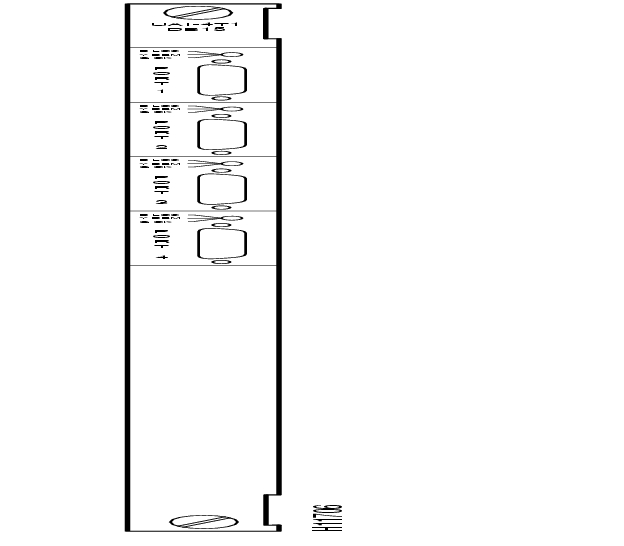
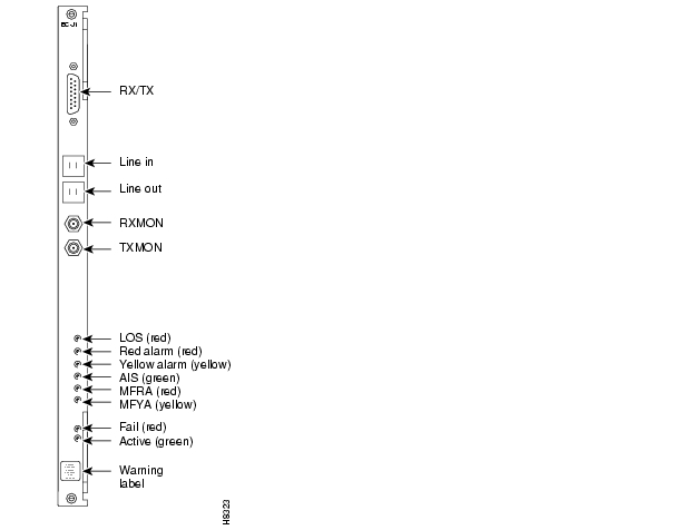
T1 Interface Back Card (BC-T1)
The BC-T1 back card provides a T1 line interface for a CVM card. It provides the following:
•
•
•
•
•
•
•
B8ZS supports clear channel operation because B8ZS eliminates the possibility of a long string of 0s. B8ZS is preferable whenever available.
The back cards support two clock modes. You select the mode through software control (cnfln on the CLI). The clock modes are normal clocking and loop timing.
With normal clocking, the BC-T1 supplies the transmit clock for outgoing data (towards the CPE).
With loop timing, the BC-T1 uses the receive clock from the line for the incoming data and redirects this receive clock to synchronize the transmit data.
BC-T1 Faceplate Description
and provide information on the faceplate of the BC-T1. When you correlate the descriptions in the table with the callouts in the figure, read from the top of the table to the bottom. The standard port connector is a female DB15.
Figure 4-30 BC-T1 Faceplate
Table 4-28 BC-T1 Connections and Status LEDs
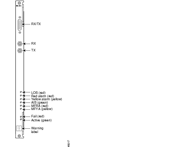
E1 Interface Back Card (BC-E1)
The BC-E1 back card provides an E1 line interface for a CVM. It has the following features:
•
•
•
•
•
•
•
•
The back cards support two clock modes. You select the mode through software control (cnfln on the CLI). The clock modes are normal clocking and loop timing.
With normal clocking, the BC-E1 supplies the transmit clock for outgoing data (towards the CPE).
With loop timing, the BC-E1 uses the receive clock from the line for the incoming data and redirects this receive clock to synchronize the transmit data.
The node keeps statistics on most line errors and fault conditions, including the following:
•
•
•
•
•
•
•
•
shows and lists status LEDs and connections on the BC-E1 faceplate.
Figure 4-31 BC-E1 Faceplate
Table 4-29 BC-E1 Connections and Status LEDs
BC-J1 Description
The BC-J1 back card provides a Japanese J1 circuit line interface for a CVM. The BC-J1 does the following:
•
•
•
•
•
•
The back cards support two clock modes. You select the mode through software control (cnfln on the CLI). The clock modes are normal clocking and loop timing.
With normal clocking, the BC-J1 supplies the transmit clock for outgoing data (towards the CPE).
With loop timing, the BC-J1 uses the receive clock from the line for the incoming data and redirects this receive clock to synchronize the transmit data.
shows a BC-J1 faceplate. lists BC-J1 connections and status LEDs.
Table 4-30 BC-J1 Connections and Status LEDs
Figure 4-32 BC-J1 Faceplate
The TDM Transport Feature
This section applies to only CVMs (and CDPs in an IPX node) that are Model C. Model C provides a service called Time Division Multiplexing Transport (TDM Transport). TDM Transport bundles DS0s to form a single, transparent connection through the network. TDM Transport is most valuable for transporting TDM data from trunks in older, non-Cisco WANs. For setup instructions, see the Cisco IGX 8400 Series Installation and Configuration publication and the command descriptions in the Cisco WAN Switching Command Reference publication.
Model C Features
The Model C firmware features are as follows:
•
•
•
•
•
Model C Limitations
The limitations on TDM Transport within Model C firmware are as follows:
•
•
•
•
•
•
•
•
•
•
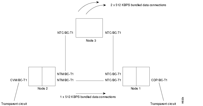
Inverse Multiplexing
To achieve full T1 and E1 rates on a single CVM or CDP, TDM Transport supports inverse multiplexing. shows a simple example. In this example, the three bundled 512-Kbps data connections symbolized by the arrows add up to a T1 connection.
Figure 4-33 Inverse Multiplexing
Frame Relay Cards
This section describes the Frame Relay service cards. The Frame Relay cards consist of the UFM (Universal Frame Module) family of front and back cards and the FRM (Frame Relay Module) family of front and back cards. The first part of this section contains information that applies to both the UFM and FRM card sets. Subsequent sections contain information that is particular to individual front and back cards. The Frame Relay and individual card topics are:
•
•
•
•
•
•
•
•
•
See the Cisco IGX 8400 Series Installation and Configuration publication for installation steps. For technical details on the line types of individual back cards, see the appendix titled "System Specifications". For a description of Frame Relay on a FastPAD, see the section titled " Data Cards" later in this chapter.
Introduction
This section lists information that applies to Frame Relay service. The first list describes functions at the node-level and the network interface. The second list contains card-specific information.
An IGX Frame Relay network features the following:
•
•
•
The UFM supports frame-forwarding with network interworking but not service interworking.
•
•
The FRM and UFM front cards perform the following functions:
•
•
•
•
•
•
•
•
On the receiving end, the UFM, FRM, or FRM-2 card set checks arriving frames against the embedded Frame Check Sequence (FCS) code and discards any non-compliant frames.
The card places Frame Relay data into FastPackets. Frame relay flag bytes and bit-stuffing provide frame delimiting and transparency. If a user-data byte has a value of hexadecimal 7E, the card changes it by inserting 0s, so that the card does not process the byte as a flag. (The Frame Relay card uses flag bytes to fill partial FastPackets.)
Maximum Connections Per Port With Signaling Protocols
For any Frame Relay card set that has a maximum frame length of 4510 bytes, the type of signaling protocol you may (optionally) specify with cnffrport results in a limit on the number of connections per physical or logical port. The maximum number of connections per port for each protocol is:
•
•
•
Neither addcon nor cnffrport prevents you from adding more than the maximum number of connections on a port. (You might, for example, use cnffrport to specify an LMI when too many connections for that particular LMI already exist.) If the number of connections is exceeded for a particular LMI, the LMI does not work on the port, the full status messages that result are discarded, and LMI timeouts occur on the port. A port failure results and also subsequently leads to a-bit failures in other segments of the connection path.
Frame Relay Over T1 and E1 Lines
On an IGX node, Frame Relay over a T1 or E1 line requires one of the following combinations:
•
•
A Frame Relay T1/E1 connection can terminate on any Frame Relay Interface—V.35, X.21, T1 or E1.
Frame relay over a T1 or E1 interface supports groups of DS0 timeslots in a logical port. A logical port is a single DS0 or a group of contiguous DS0s. Logical ports consisting of multiple DS0s operate at the full rate of 64 Kbps per timeslot. If a logical port consists of a single DS0, you can configure either 56 Kbps or 64 Kbps. See .
If the rate on a logical port is 56 Kbps, the Frame Relay interface strips the least significant (signaling) bit from the incoming octet and puts a 1 in the least significant bit of the outgoing octet. The 56-Kbps rate typically applies to a groomed Digital Data Services (DDS) circuit that uses a T1/E1 line.
Note
Figure 4-34 Multiple and Single DS0s Forming a Logical Port
Universal Frame Module
The Universal Frame Module (UFM) cards support a much higher port density than the FRM cards and support ELMI and Frame Relay-to-ATM service interworking. The front card (UFM-4C or UFM-8C) can support Frame Relay traffic on a maximum of 4 or 8 T1 or E1 ports on a back card. The front card (UFM-U) can support Frame Relay traffic on 12 V.35 ports, 12 X.21 ports, or 4 HSSI ports on a back card.
The next sections describe the UFM-C card sets. Subsequent sections describe the UFM-U card sets.
UFM-C Front Card
The Universal Frame Model (UFM-C) supports either 4 or 8 T1 or E1 ports per back card. The UFM-4C supports 4 ports regardless of the presence of the 8 connectors on the UFI back card. The UFM-8C supports all 8 ports. Both models of the UFM-C support 1 to 24 or 1 to 31 DS0s per physical line.
The UFM-C can also operate unchannelized for E1 only, with 32 DS0s constituting one unchannelized E1. In the unchannelized mode, one logical E1 port maps to one E1 line.
lists the front and back cards described in this and subsequent sections.
Table 4-31 Channelized UFM Card Sets
The characteristics and functions of the UFM-C are as follows:
•
•
•
•
•
•
•
•
•
•
•
•
•
•
•
•
•
shows a UFM-C faceplate. If the label on the faceplate shows "UFM C," the front card is a UFM-8C, which most UFMs are. The UFM-4C label shows "UFM-4C."
Figure 4-35 UFM-C Faceplate
Table 4-32 UFM-C Faceplate Indicators
UFI-8T1 Back Card
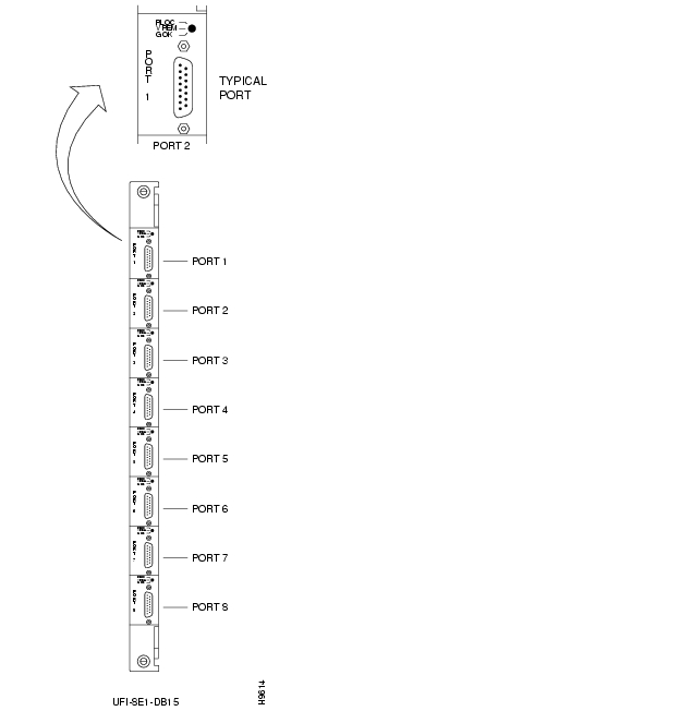
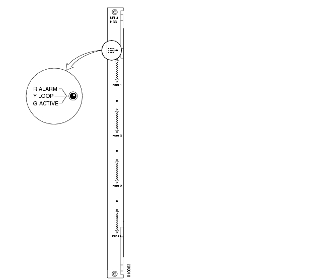
The Universal Frame Interface 8T1 (UFI-8T1-DB15) back card has 8, bi-directional, DB15 connectors. See . For each port, one tri-color LED displays the status, as the emphasized area of shows. The line is inactive if the LED is off. See .
Figure 4-36 UFI-8T1-DB15 Faceplate
Table 4-33 UFI 8T1 Port LED Indicators
Green
On indicates line is active.
Red
On indicates line is active, but a local alarm was detected.
Yellow
On indicates line is active, but a remote alarm was detected.
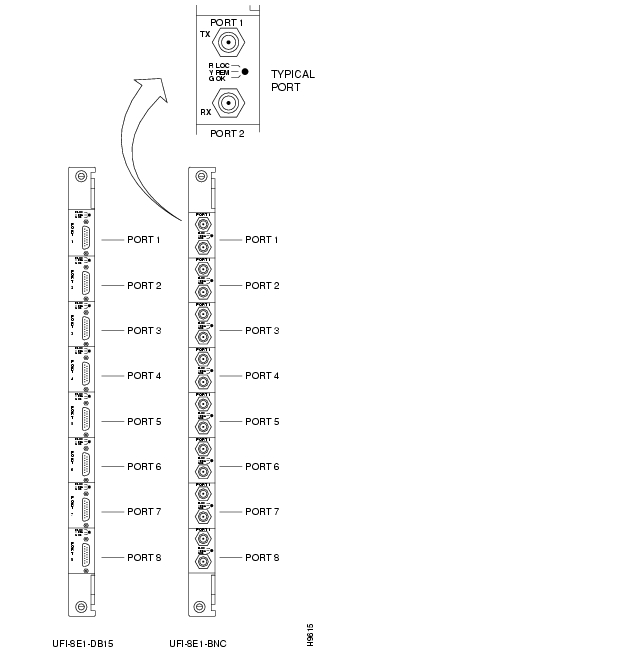
UFI-8E1 Back Cards
Universal Frame Interface 8E1 cards have connectors for 8 E1 ports. The UFI-8E1-DB15 has 8 bi-directional DB15 connectors. The UFI-8E1-BNC has 16 BNC connectors (2 per port). See . Each port has a tri-color LED for status display. See . The line is inactive if the LED is off.
Table 4-34 UFI 8E1 Faceplate Indicators
Green
On indicates line is active.
Red
On indicates line is active, but a local alarm was detected.
Yellow
On indicates line is active, but a remote alarm was detected.
Figure 4-37 UFI-8E1-DB15 and UFI-8E1-BNC Faceplates
UFM-U Front Card
This section contains the following:
•
•
•
•
The back cards that provide line interfaces to the UFM-U are the:
•
•
•
The features and operational characteristics of the UFM-U card sets are as follows:
•
•
•
•
•
•
•
•
•
•
•
•
•
•
•
•
•
•
•
•
•
•
•
The aggregate throughput you can configure across all ports is 24.576 Mbps. The 24.576 Mbps is the maximum line speed and is the over-subscription ceiling. The actual data throughput of the card depends on the hardware and the frame size. As the frame size decreases, the throughput decreases. With a frame size of 200 bytes of more, for example, the sustainable throughput is 16.384 Mbps. With 100-byte frames, data may be dropped if the rate is 16.384 Mbps for significant time periods.
For a description of Cisco Frame Relay technology, see the Cisco System Overview publication.
UFM-U Faceplate
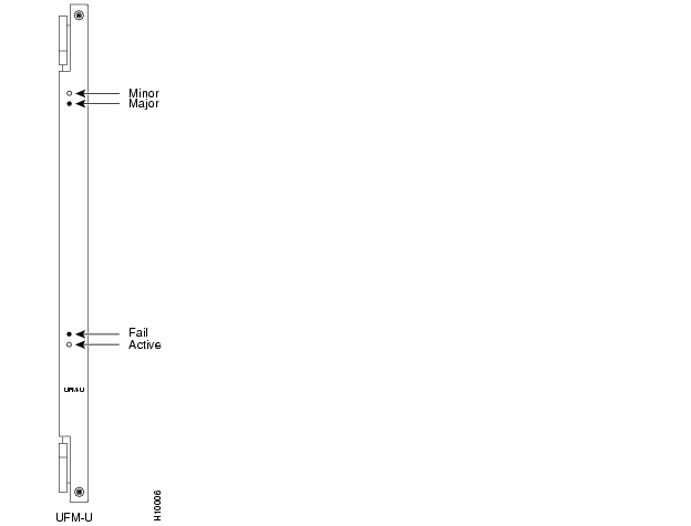
shows the faceplate of the UFM-U. describes its LED indicators. The first two columns of shows the names of the LEDs and possible combinations of on and off states. The "Description" column describes the meaning of the LED states.
Figure 4-38 UFM-U Faceplate
Table 4-35 UFM-U Card LED Indicators
Port Speeds on the Unchannelized UFM
This section describes how to specify active ports and the maximum speed allowed on each active port. Specifying the maximum speed for active ports requires careful planning, and this section provides the information for understanding and planning the port specification.
The hardware does not permit random combinations of speeds across the ports. Hardware constrains the speeds to certain combinations of maximum rates on active ports. The combination of maximum speeds and active port numbers is called the mode of the card. shows the maximum port speeds and additionally groups the ports under a letter. If you need to change the mode of a card after connections have been added, you must consider these port groups. The forthcoming section titled " Changing the Mode of a UFM-U" describes the application of port groups.
In rows 1 through 27 of , the numeric value is the maximum bit rate for the V.35, X.21, or HSSI port. The V.35 and X.21 ports have column headings 1 through 12 (and subheadings consisting of a group letter), and the HSSI port numbers are 1 through 4.
The maximum aggregate throughput is 16 Mbps. Note that, although the cnfmode command lets you specify the maximum for each active port, you specify the actual bit rate for a port with either the cnfport or cnffrport command. In :
•
•
•
•
Note
Table 4-36 Maximum Port Speed Modes on the UFI Back Cards
Changing the Mode of a UFM-U
Initially, an unchannelized UFM card set comes up in mode 1. To specify another mode, use either cnfmode or cnfufmumode. The preferable time to specify a mode is before you add connections. After connections exist on the card, you must delete some or all connections and down ports before you change the mode. To change the mode of a card set, you must first delete all the connections in a group and down all the active ports in a group if any maximum port speed changes in a group as a result of the mode change. This requirement means you may or may not have to delete connections in a particular group. Use to follow two examples that illustrate what you must do before you change modes.
1
2
The steps for changing the mode of a UFM-U when connections exist on the card is as follows:
Step 1
Step 2
Step 3
Step 4
Step 5
Step 6
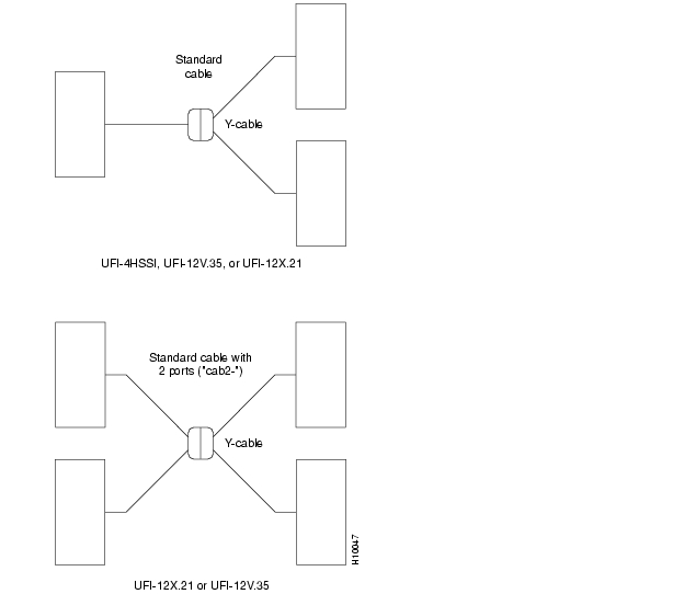
Cabling for the UFM-U Back Cards
This section describes the standard cabling and the Y-cabling scheme for the unchannelized back cards. The back cards are the UFI-12V.35, UFI-12X.21, and UFI-4HSSI. Because of the port variety and because the cables are either DCE or DTE, a significant number of cable configurations exist. shows cable names, part numbers, and descriptions.
The connectors on the UFI cards are high density. Each UFI-12V.35 and UFI-12X.21card has 6, 60-pin connectors. Each of these connectors has two ports. If your specification dictates that both ports on a connector are active, you must have a cable with wiring for two ports. If a part number in has the form "CAB-2...," the cable has wiring for two ports. Note that if both ports on a connector are active, both ports must be either DCE or DTE because the cable itself is either DCE or DTE. If a connector has only one active port, the cable can be the less expensive, single-port version. A HSSI connector has 50 pins and supports one port.
Table 4-37 UFM-U Cables
Port redundancy through the use of a Y-cable requires two card sets, at least one Y-cable, and the standard cabling. On a UFI-4HSSI, Port 1 is the only port that supports Y-cable redundancy. On the V.35 and X.21 UFIs, redundancy at more than one connector requires a corresponding number of Y-cables and standard cables. The standard cables are either single-port for HSSI, V.35, or X.21 or dual-port for the X.21 and V.35 UFIs.
To set up the Y-cabling, you attach a branch of the "Y" at the primary and redundant connectors then attach the near end of the standard cable to the base of the "Y." illustrates single and dual-cabling in a Y-cable setup. The single-cable arrangement applies to HSSI, V.35, and X.21. The dual-port redundancy setup applies to a UFI-12X.21 or UFI-12V.35, where both ports within the UFI connector are used in a Y-cable redundancy scheme.
Figure 4-39 Y-Cabling With a UFI-4HSSI, UFI-12V.35, or UFI-12X.21 Port
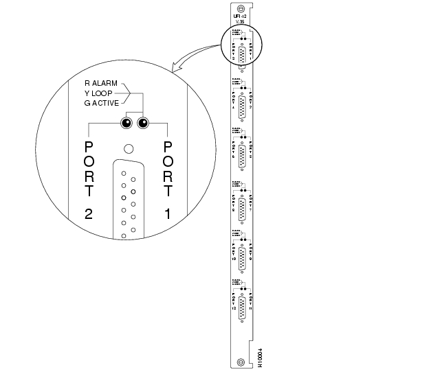
UFI-12V.35 Back Card
The UFI-12V.35 has six connectors. Each connector contains two V.35 ports. Each port has a tri-color LED to indicate its status. Because each connector supports two ports, each connector has two associated LEDs. shows the faceplate of the UFI-12V.35, and describes the significance each color of the LED.
You can configure each port on the UFI-12V.35 to use normal clocking or a looped clocking, then configure the port to run at one of the following speeds:
•
•
•
Figure 4-40 UFI-12V.35 Faceplate
Table 4-38 UFI-12V.35 Faceplate Indicators
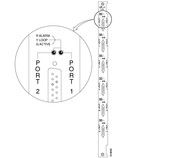
UFI-12X.21 Back Card
The UFI-12X.21 has six connectors. Each connector contains two X.21 ports. Each port has a tri-color LED to indicate its status. Because each connector supports two ports, each connector has two associated LEDs.
You can configure each port on the UFI-12X.21 to use normal clocking or a looped clocking, then configure the port to run at one of the following speeds:
•
•
•
shows the faceplate of the UFI-12X.21, and describes the significance each color of the LED.
Table 4-39 UFI 12-X.21 Faceplate Indicators
Figure 4-41 UFI-12X.21 Faceplate
UFI-4HSSI Back Card
The UFI-4HSSI has four connectors. Each connector has a tri-color LED for status. shows the UFI-4HSSI faceplate. describes the significance each color of the LED. Using cnffrport, you can configure each port with a speed that is a multiple of 1 Mbps up to the maximum for the mode of the card (see the section titled " Port Speeds on the Unchannelized UFM").
Figure 4-42 UFI-4HSSI Faceplate
Table 4-40 UFI-4HSSI Faceplate Indicators
Frame Relay Module (FRM)
The Frame Relay Module (FRM) front card supports 1 to 4 data ports and, in single-port mode, operates at up to 2.048 Mbps.
Note
Table 4-41 Frame Relay Module (FRM) Card Sets
FRM Features and Functions
The FRM supports a maximum port speed of 2.048 Mbps plus the following features:
•
•
•
•
•
•
•
•
•
•
•
The FRM can support a maximum of 252 virtual circuits (PVCs). PVC distribution can cross all four ports if they do not exceed the 252 PVC limit and the limit of 2.048 Mbps per FRM.
Bundled and grouped connections are software groupings of multiple virtual circuits within a single routing connection. Grouping allows a node to support up to 1024 virtual circuits, which is the logical equivalent of four FRMs.
Frame Relay Card Redundancy
Frame relay card redundancy can be provided through a second card set in adjacent slots and a Y-cable between each port that connects to the user-equipment. See for an illustration. The hardware kits for this feature contain a second Frame Relay card set, a set of Y-cables to interconnect the two card sets, and any other pieces that apply to the card types. Y-cable redundancy is not possible using back cards with different interfaces, such as an FRI T1 and FRI V.35.
Figure 4-43 Frame Relay Port Redundancy
Frame Relay Interface (FRI) V.35 Card
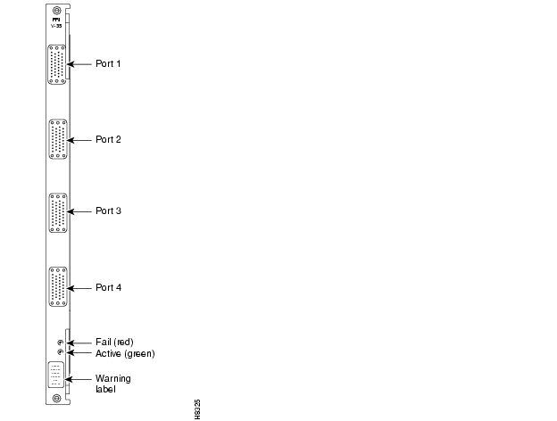
The Frame Relay Interface V.35 (FRI-V.35) is a four-port back card to the FRM card. Two models of the FRI-V.35 can support the FRM:
•
•
The FRI-V.35 has the following functions and features:
•
•
•
•
•
Figure 4-44 Frame Relay V.35 Connectors and Indicators
shows the relationship between the number of ports used on the FRI and maximum operating speed for each port. Model A FRM and FRI cards are included for early users who may not have updated the cards. Note that the port numbers start at the top on the FRI faceplate.
Table 4-42 Port Speed Combinations
Frame Relay V.35 Port Numbering
Each Frame Relay logical channel has a number in the form:
slot.port.dlci
where
•
•
•
FRI-V.35 Data Clocking
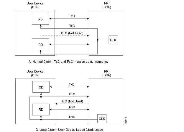
The two clocking modes that the FRI supports are normal and looped. illustrates the two modes. Note that the direction for the clock and data is reversed for the two FRI mode configurations (DCE or DTE), as follows:
•
•
•
•
Figure 4-45 Frame Relay Data Clocking Modes
Note
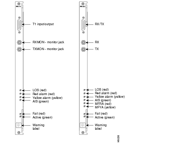
illustrates the FRI-T1 and FRI-E1 back cards.
Figure 4-46 Frame Relay T1/E1 Back Cards
Loopbacks
The IGX node does not support port loopbacks (tstport and addextlp command) towards the IGX node. In contrast, for V.35 and X.21 interfaces only, you can set up connection loopbacks towards the facility by using the addloclp and addrmtlp commands.
FRM-FRI Compatibility
The firmware on the front card must match the type of interface on the back card. Rev D firmware on the FRM supports X.21 and V.35 protocols. Rev E firmware on the FRM supports T1 and E1 protocols. The Display Card (dspcd) command indicates the type of back card that the FRM firmware supports and reports any mismatch.
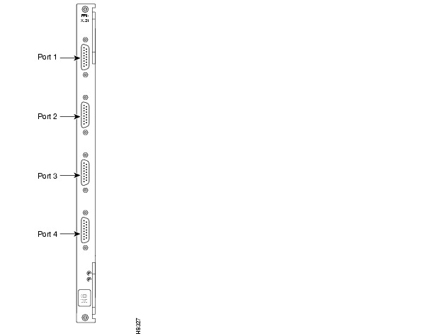
Frame Relay Interface for X.21
The FRI-X.21 back card provides an X.21 interface to the user equipment. The two model D FRI cards are the FRI-V.35 and FRI-X.21. They differ only in the physical connectors (see ). The operating rates of each port and the composite data rate supported by the FRI-X.21 card is the same as the FRI-V.35. You can configure each port as either a DCE or a DTE. Another FRI card is the FRI-2-X.21. This is the back card that provides the interface between the Port Concentrator Shelf (PCS) and the FRM-2. See the section titled " FRM-2 Interface to the Port Concentrator Shelf."
The FRI-X.21 uses leased line service for international networks. The V.35 version is for domestic (U.S.) use and also uses a leased line service for its connections. The FRI-X.21 back card features:
•
•
•
•
•
FRI configuration supports one to four ports. The configuration depends on the maximum speed requirement (the card itself has a maximum composite speed). shows the FRI faceplate. lists the available port operating speeds.
Any one port can operate at 2048 Kbps. Any combination of ports can equal 2048 Kbps. If a port is operating at 2048 Kbps, it must be port 1, and no other port can be active. Numbering of the 4 DB15 connectors starts at the top of the faceplate. lists the cable and pinouts for an X.21 port.
Table 4-43 FRI Card Types
FRI-X.21
X.21
4 ports
DB15 Sub miniature, female
FRI-V.35
V.35
4 ports
34-pin MRAC type (Winchester), female
Table 4-44 Frame Relay Port Speeds Available
Any multiple of 56 Kbps
Up to 1.792 Mbps
Any multiple of 64 Kbps
Up to 2.048 Mbps
Table 4-45 FRI-X.21 Port Pin Assignments (DB 15-connector)
Figure 4-47 Frame Relay X.21 Connectors and Indicators
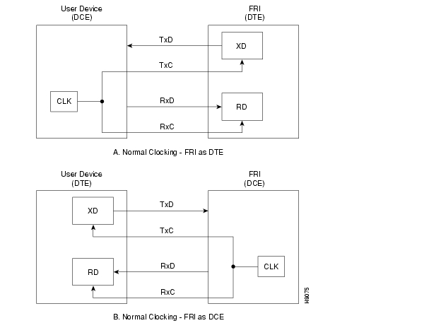
X.21 Data Clocking
The FRI-X.21 supports only normal clock mode. The direction of the clock and data lines is reversed if the FRI is configured as a DCE or as a DTE as follows (see ):
•
•
Figure 4-48 Frame Relay Data Clocking Modes
Y-Cable Redundancy and Port Modes
The Y-cable redundancy kits for the FRI-X.21 and FRI-V.35 contain four extra daughter cards for specifying individual ports as either DCE or DTE. The extra daughter cards are 200-Ohm versions for the FRI already installed. The higher impedance cards are necessary because of circuit behavior at higher speeds when the two interfaces are in parallel (by way of the Y-cable).
Card Self Test
As with all IGX cards, the FRI-X.21 includes internal diagnostic routines that periodically test the card's performance. These self-test diagnostics automatically start and run in background. They do not disrupt normal traffic. If a failure is detected during the self test, the faceplate red Fail LED is turned on. The operator can also view the status at the control terminal by executing the Display Card (dspcd) command.
A report of a card failure remains until cleared. A card failure is cleared by the Reset Card (resetcd) command. The two types of reset that resetcd can do are hardware and failure. The failure reset clears the event log of any failure detected by the card self-test but does not disrupt operation of the card. A reset of the card firmware is done by specifying a hardware reset. This reboots the firmware and momentarily disables the card. If a redundant card is available, the hardware reset causes a switch over to the standby card.
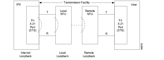
Port Testing (X.21)
The X.21 Frame Relay ports and any associated external modems, CSUs, or NTUs can be tested using data loopback points in the circuit path. The three possible loopbacks for X.21 Frame Relay ports are:
•
•
•
The modems must be compatible with the Cisco loopback protocol. For information on supported modems and protocols, refer to the appendix titled "Peripherals Specifications" in the Cisco IGX 8400 Series Installation manual. Also, refer to the Cisco WAN Switching Command Reference for protocol requirements for the addextlp, addloclp, and addrmtlp commands. For information that applies to loopbacks on the FRM-2/FRI-2 and PCS, see the descriptions of these loopback commands in the Cisco WAN Switching Command Reference. If these sources fail to clarify a particular situation, contact the Cisco TAC.
All three loopbacks are set up using the tstport command. Only one port at a time can be in loopback mode for testing.
The internal loopback point is established inside the FRI card. illustrates the setup. The FRM generates a test pattern, sends it out on the transmit circuitry, and detects this pattern on the receive circuitry. This test takes several seconds and momentarily interrupts traffic on the port. The test runs on a port that is in either DCE or DTE mode.
Figure 4-49 Frame Relay Loopback Modes
For ports configured for DTE, the two additional tests (local loopback and remote loopback) are available. For these ports there are two methods of loopback testing:
•
•
Unit Replacement
FRI card replacement is the same as other back card replacement. For back card replacement procedures, refer to the Cisco IGX 8400 Series Installation and Configuration publication.
FRM-2 Interface to the Port Concentrator Shelf
This section introduces the Port Concentrator Shelf (PCS) for Frame Relay traffic. The PCS is an external device that expands the capacity of a Frame Relay Module (FRM) to 44 low-speed ports. This ability to increase the port density of an IGX switch supports more efficient usage for the common switch equipment. The port parameters are as follows:
•
•
•
The PCS requires a version of the FRM/FRI card set that is exclusively dedicated to the PCS. The front card is the FRM-2. The back card that interfaces the FRM-2 to the PCS is the FRI-2-X.21. illustrates the relation ship between the FRM/FRI card set and the PCS. It provides one or more X.21 links. Each X.21 link is called a concentrated link. In a full configuration, each concentrated link services one of four 11-port modules in the PCS. This makes a total of 44 ports on the FRM-2.
Note
For more detailed information on the PCS, refer to the section on the Port Concentrator Shelf in the System Manual. For detailed installation instructions, refer to the Port Concentrator Installation document that comes with each unit. Cabling information for the PCS appears in the cabling appendix and in the Port Concentrator Installation document.
Figure 4-50 Port Concentrator Shelf Components
Terminology
The following terms are used to identify PCS components:
•
•
Operation and User Interface
Other than front panel LEDs, the PCS has no user interface because the PCS functions as an extension of the FRM-2. PCS ports are operated and maintained from the IGX user interface.
The PCS operates within the IGX environment as a Frame Relay card with 44 ports. Existing Frame Relay commands (cnffrport, upfrport, dnfrport, addcon, delcon, etc.) are the same in syntax and function. The difference is that a range of 44 ports can be specified instead of 4. The configuration of each of the PCS logical ports is similar to that of non-PCS Frame Relay ports. A Frame Relay card connected to a PCS notifies the system database and permits the additional ports to be specified.
PCS-to-IGX Interface
This section describes the interface between the PCS and IGX node.
Compatibility
The PCS requires the following:
•
•
Note
Concentrated Link
The concentrated link refers to the connection between port concentrator and Frame Relay card. Each module supporting 11 external ports is connected to 1 of the 4 ports on the FRI-2-X.21 back card.
Configuration
Each of the four composite links between an PCS and IGX node has a fixed configuration of:
•
•
•
The PCS Concentrated Link cable is illustrated in the cabling appendix. Its maximum length is 25 feet. You cannot use a modem to extend this distance.
Activation
FRM-2 firmware interacts with the PCS over composite links only if the FRM-2 is active. The FRM-2 changes from standby to active state when its first logical port is activated.
upfrport Command
A PCS logical port associated with an FRM-2 card is activated with the upfrport command. The upfrport command requires the slot number of the FRM-2 to which the PCS is connected. Enter the slot number and a logical port in the range of 1-44 (assuming a connection exists for all 4 composites between the PCS and IGX node).
Example: upfrport 4.1
This example indicates that the FRM-2 in slot 4 and concentrated link 1 are connected.
Entering the upfrport command for one port activates all four ports. The following events are generated by successful activation of four concentrated links. The display is from the example "upfrport 4.1:"
"Info FRM 4 Activated"
"Info FRM Port 4.1 Activated"
"Info FRM Concentrated Link 4.1 Failure Cleared"
"Info FRM Concentrated Link 4.2 Failure Cleared"
"Info FRM Concentrated Link 4.3 Failure Cleared"
"Info FRM Concentrated Link 4.4 Failure Cleared"A noticeable delay occurs after upfrport begins executing on the first port. During initial upfrport execution, the FRM-2 performs first-time configuration, diagnostic, and up/download functions.
If a concentrated link is not connected or fails to come up, the logical port remains in a failed state until either the link comes up or the port is deactivated with the dnfrport command.
De-activation: the dnfrport Command
The FRM-2 card set returns to the standby state after you de-activate all 44 logical ports by executing the dnfrport command.
PCS Port Configuration
When the Frame Relay ports are activated, the IGX node recognizes them as PCS-connected ports. Subsequently, all applicable Frame Relay port management commands accept logical port numbers in the form slot.port. The range for port is 1 to 44. shows the logical ports the PCS supports. In , slot is the IGX slot in which the FRM-2 resides.
Table 4-46 PCS Logical Ports
Composite L1
slot.1—slot.11
Composite L2
slot.12—slot.22
Composite L3
slot.23—slot.33
Composite L4
slot.34—slot.44
Interface Hardware Configuration
The interface and clocking characteristics for each PCS port is independently configured to be V.11 (X.21), V.35, or V.28 by inserting the required interface card (or "ICARD") into the associated slot in the PCS. For detailed information on PCS hardware interfaces, refer to the Port Concentrator Installation document. This document comes in the PCS shipping container.
The IGX node does not have the capacity to read the type of interface present for the PCS port. The values you enter under Interface Type with the cnffrport command appear in the display only and cannot be checked against the hardware.
The cnffrport Command
You configure a PCS with the cnffrport command. With the following limitations, all parameters for the cnffrport command are supported:
1
2
3
4
Port Statistics
All Frame Relay summary and interval statistics are kept for PCS ports. The PCS and FRM-2 share responsibility for statistics collection on PCS ports. The PCS maintain counters for:
•
•
•
•
All remaining statistics counters are collected by the FRM-2. Although an IGX node supports ForeSight for PCS connections, CLLM (ForeSight) statistics are not available in Release 8.1. These fields are present but not valid.
PCS Monitoring Functions
Monitoring functions generally apply to the PCS except that you can specify up to 44 logical ports for a FRM-2 slot. For descriptions of the monitoring commands, refer to the "Troubleshooting" chapter of the Cisco WAN Switching Command Reference. Note that commands dspchcnf, dspchstats, dspportstats, and dspbob fail when the required concentrated link is down. Trying to execute one of these commands on a concentrated link that is down causes an error message to appear.
Collecting the Monitoring Information
The sections that follow describe the collection of various types of monitoring information.
Logical Port Speed
The PCS measures the speed of receive data on logical ports if the port is configured as a DTE interface. To see the measured speed, use the dspbob command. The PCS measures port speed after any of the following occurs:
•
•
•
•
The process of measuring port speed sends out two 1-byte frames with no CRC on the port.
Physical Port Speed
The IGX node measures the physical port speed for FRI-2-X.21 ports once per minute. The current measured speed is displayed with the dspfrcport command and should always read 512 Kbps when the port is active.
PCS Front Panel LEDs
describes the LEDs on the PCS front panel.
Table 4-47 PCS Module Front Panel LEDs
Card Insertion and Removal
If the FRM-2 or FRI-2.X21 card is removed for any reason, be sure to maintain card compatibility upon card replacement: the FRM-2 card is compatible with only the FRI-2-X.21 back card. The IGX node declares a mismatch state for any other back card inserted into an active FRM-2 slot. Inserting compatible hardware is the only way to clear the mismatch. Similarly, once an IGX slot is active with an FRM-2, a mismatch is declared if any other front card is inserted into this slot. Before the slot can be used for any other type of card, the slot must be de-activated as a PCS-capable Frame Relay card.
PCS Command Summary
The commands in the list that follows apply to PCS Frame Relay ports. Most commands have the syntax described in the Cisco WAN Switching Command Reference with the exception that system software recognizes 44 ports per FRM-2 instead of 4. Some commands are PCS-specific.
Table 4-48 Commands for the Port Concentrator Shelf
PCS Port Failures
A PCS logical port failure is defined as a minor alarm. The FTC/FRP Port Comm Failure icon appears in the dspalms screen. Any connection that terminates on a failed port is also failed. Three causes of a port failure are defined, as described under Alarms and Events.
Conditioning
A failed connection on a PCS logical port is conditioned in the same manner as a failed connection on a non-PCS FRP port. Only the active control template is supported on PCS ports. The "conditioned" control template should not be used for PCS logical ports.
PCS General Operation
Firmware Download
When it detects a Port Concentrator on one of its links, the FRM-2 checks for a compatible firmware revision on the Port Concentrator. If the FRM8-2 detects that the firmware on the Port Concentrator is incompatible, the FRM8-2 downloads the current firmware to the Port Concentrator. This download operation takes about two minutes. An event is logged when a firmware download has either started or failed.
Operating software on the Port Concentrator is stored in Flash memory. Download should be required only if the PCS is connected to an FRM-2 with newer firmware or a PCS module is replaced and a software version difference exists.
Automatic Diagnostics—FRM-2 and FRI-2-X.21 Cards
The FRM-2 card runs a self-test diagnostic when it is in the standby state. The system software uses a reserved channel on the FRM-2 card to perform background loopback tests that include both the FRM-2 and FRI-2-X.21. This test verifies that all components up to the FRI-2-X.21 physical port are functioning. These diagnostics do not test the PCS.
Cisco WAN Manager Interface
Information about PCS logical ports and Frame Relay connections automatically goes to Cisco WAN Manager. Cisco WAN Manager can also manage connections and other FRM-2 port functions.
SNMP Manager
The SNMP agent supports Port Concentrator logical ports. This includes configuring PCS port parameters, adding, or deleting Frame Relay connections, and retrieving statistics.
The SNMP agent also supports provisioning for 44 Frame Relay ports for FRM-2; the existing MIB variables are extended to the expanded number of logical ports. SNMP management functions are not supported for the Port Concentrator concentrated links.
User Interface
Interaction between the FRM-2 and PCS automatically updates the database to display the number of connected logical FRM-2 ports at the PCS. As a result, both the IGX user interface and the Cisco WAN Manager interface automatically display the additional capacity of 44 ports for the FRM-2.
Concentrated Link Failure
If, during normal operation, communication between FRM-2 and PCS over a concentrated link stops, a concentrated link failure alarm results.
In addition, during start-up, a concentrated link is failed for any of the following reasons:
•
•
•
•
Frame Trunk Module (FTM)
The Frame Trunk Module (FTM) supports devices that provide access for various types of traffic to the IGX node. Two lines of access devices are supported by the FTM. One series is the FastPAD family of products. The FastPADs support Frame Relay, voice, and serial data. The other series is the Cisco line of access devices.
The Cisco Line of Access Devices for WAN Switches
An example of the Cisco line of access devices for the IGX WAN switches is the Cisco 3810 family of products. The Cisco access devices run the Cisco IOS (operating system) and have a control terminal separate from the node's control terminal. The access device itself takes IOS commands, but once a control session has been established, you control the interface between the node and the access device through Cisco WAN Manager or by using commands on the command line interface (CLI). For descriptions of the CLI commands that apply to the FTM and connections to the Cisco access devices, refer to the Cisco WAN Switching Command Reference publication. Individual publications also exist for the Cisco access devices. Currently, you can refer to the Cisco 3810 Installation publication and the Cisco 3810 Software Configuration Guide and Command Reference publication.
For the Cisco access devices, you can add connections between the following endpoints:
•
•
•
Note that, when you add connections between a 3800 on an FRM to a CDP or CVM, you must add the connections at the CDP or CVM. The FTM and FRP or FRM endpoints, you can add connections at either end. For more information on setting up connections between the Cisco 3810 access devices and an FTM, FRP/FRM, or CVM, refer to the Cisco IGX 8400 Series Installation and Configuration publication.
The FastPAD Line of Access Devices
The interface cards for FastPADs are the FTM front card and FPC back card. The back card provides either a T1, E1, V.35, or X.21 interface. Each FPC V.35 or FPC X.21 provides four ports. Each port can support one FastPAD either locally or remotely (via modem). The T1 card has a DB15 for RX/TX and an alternate pair of RX/TX BNC connectors. The E1 connections are the same except for additional RX/TX-monitoring BNC connectors. Y-cable redundancy is also supported. shows the FTM front card and the FPC-V.35.
Note
You enter commands that manage the FTM/FPC, FastPAD, and their ports and connections. Cisco WAN Manager collects statistics related to cards, ports, and FastPADs. FTM/FPC card management includes detection of card installation or removal, mis-matched back cards, or Y-cable redundancy.
Figure 4-51 FastPAD Cards: FTM and FPC (V.35)
Port management includes EIA signaling, LMI alarms, upping and downing of ports, and the collection of port statistics available to Cisco WAN Manager.
FastPAD management permits the management of cards and ports on the FastPAD device from the IGX node. This management includes card and card removal detection, card mismatch, uploads and downloads between the FastPAD and the IGX node.
Connection management involves mapping FastPAD connection to Frame Relay-type virtual circuits. Connections that originate at a FastPAD must terminate at another FastPAD. Each FTM/FPC card set supports up to 252 connections. The card set collects statistics on these connections and provides them to Cisco WAN Manager. For descriptions of the FastPAD commands and detailed information on the FastPAD, refer to the FastPAD User's Guide. Refer also to the StrataView FastPAD User's Guide.
Data Cards
A data circuit has a direct interface to the IGX node through either a High-speed Data Module (HDM) or Low-speed Data Module (LDM) card set. The HDM set consists of an HDM front card and a Synchronous Data Interface (SDI) back card. The LDM set consists of an LDM front card and a Low-speed Data Interface (LDI) back card. The back cards match the circuit type to the front card. Synchronous data card sets are listed in . An IGX 8430 node can have up to 25 HDM/LDM sets in a non-redundant system, for support of up to 200 full-duplex data connections.
The synchronous data cards support the ability to configure and monitor EIA leads; the ability to configure each channel for clocking, data rate, and DTE or DCE interface type; and complete loopback testing capability. Data channels can support null modem emulation as well as constant-carrier and switched-carrier operation. Data interfaces are transparent with respect to protocol. Asynchronous, binary synchronous, and bit synchronous protocols are supported with no impact on host or terminal software.
Table 4-49 Synchronous Data Cards Available
High-speed Data Module (HDM)
The HDM front card in an IGX node is a programmable communications processor that can support one to four high speed, synchronous data channels. It operates at speeds from 1.2 Kbps up to
1344 Kbps on all four ports while performing link error monitoring.The HDM front data card:
•
•
•
•
•
An internal baud rate generator provides transmit and receive data clocks to the SDI card at the selected rate. The HDM can accept data from an external data device with a non network synchronized clock (isochronous clock) up to 112 Kbps. With isochronous clocking, the HDM sends a clock control signal to the other end of the circuit to synchronize the far end HDM receive clock to the isochronous clock received at the near end.
Unless specified, a packet of data for EIA control lead information is built only at a very low rate or when a change of state is detected on one or more of the control leads. The data rate is specified as either "fast" or "not fast" (the default) by the addcon command for data connections. A fast EIA lead transmission can be specified in the software to send EIA control lead information in every FastPacket (interleaved EIA mode). This tightly couples the EIA lead states with the transmitted data but reduces the bandwidth efficiency.
The HDM card is installed in a front slot. An SDI back card plugs directly into the P2 connector of the front card. The SDI back card provides the proper data channel interface.
The faceplate of the HDM has message lights and buttons for loopback control and signal monitoring. The buttons relate to loopback testing or scrolling through the FastPacket data ports for a snapshot of selected data port conditions (indicated by Port, Port Under Test, loopback, and communication line state lights). illustrates and lists the controls and indicators. When correlating the figure to the table, read from the top down.
Figure 4-52 HDM Controls and Indicators
Table 4-50 HDM Controls and Indicators
Redundancy for HDM data cards can be provided with a second front and back card set and a Y-cable connection on each port to the customer equipment. See .
Figure 4-53 HDM Data Port Redundancy
Synchronous Data Interface Card (SDI)
The SDI card is a synchronous data interface back card that directly connects to a front HDM card. Each SDI card has four connectors and provides the physical and electrical connection interface to four data ports. Each port is independently configurable for DTE or DCE mode, baud rate, and so on. One for one port redundancy is provided with a second card set and a standard Y-cable arrangement.
The SDI card:
•
•
•
•
Four types of SDI back cards can provide an interface between an HDM front card and the customer data equipment. distinguishes each type of SDI card.
Table 4-51 SDI Physical Interfaces
Three clocking modes are available on the SDI for clocking in transmit data and clocking out receive data. In addition, the SDI can operate as either a DCE or DTE, which makes possible six combinations of clocking. (See and .) With loop clocking, the user device must loop the RxC to the XTC for clocking out the transmit data.
When the SDI is configured as DTE, the user device is the source of clock timing and is generally not synchronous with the network (IGX node) timing. This is isochronous clocking. Isochronous clocking allows the customer data sets at each end of a circuit to operate at slightly different rates (non-synchronously) with minimum delay and loss of data. This feature limits the amount of data allowed to accumulate in the HDM receive buffers and forces a re-synchronization before the delay reaches an unacceptable level.
Figure 4-54 Clocking Modes for SDI in DCE Mode
Figure 4-55 Clocking Modes for SDI in DTE Mode
Isochronous clocking lets a node at the far end compensate for an unstable clock in a near-end device. Transmission in an isochronous network is reliable up to 112 Kbps. Only one input per port at a time can use isochronous clocking. The SDI does not support two isochronous clock inputs in the same direction (as required by some modems that independently generate TxC and RxC).
Note
Split clocking uses the user-device timing for timing data transmission in one direction and the IGX timing for the other direction.
Low Speed Data Module (LDM)
The LDM front card supports up to 8 synchronous or asynchronous data ports. Each port is independently configurable for DTE or DCE mode, baud rate, and so on. The LDM card is a low speed data module for use on EIA/TIA-232C ports with data rates up to 19.2 Kbps, where the higher speed capabilities of an HDM are unnecessary.
The LDM can process either synchronous or non-synchronous input data. With non-synchronous inputs, the data is over-sampled at a rate determined by how much jitter your equipment can tolerate. Using an external device is also possible for synchronizing the asynchronous data before the data enters the IGX node.
The LDM front data card:
•
•
•
Additional features, such as embedded (fast) EIA, sixth EIA lead support, and pleisochronous clocking, are also supported. The fast EIA control lead lets the user include the RTS/CTS EIA control leads in the same FastPacket as customer data. The EIA control lead status is encoded as the eighth data bit in each data byte. This provides a quick EIA response without significantly affecting bandwidth requirements. It is limited to data rates of 19.2 Kbps and below.
The LDM can reside in any empty front slot and requires an LDI back card. The LDI card plugs directly into the P2 connector of the LDM card.
The faceplate of the LDM has message lights and buttons for loopback control and signal monitoring. shows and lists these indicators and buttons. When correlating the figure to the table, read from the top down. The buttons are for loopback testing and scrolling through the FastPacket data ports to obtain a snapshot of selected port conditions (indicated by Port, Port Under Test, loopback, and communication line status lights).
Figure 4-56 LDM Connections and Indicators
Table 4-52 LDM Connections and Indicators
Redundancy for LDM data card types is available through a second front and back card set and a Y-cable connection on each port to the customer data equipment. illustrates redundancy.
Figure 4-57 LDM Data Port Redundancy
The 4-port and 8-port LDM supports only a subset of the full EIA/TIA-232C/D control leads. The LDM supports only non-isochronous DCE normal and DCE or DTE looped clocking modes, transmission of 3 EIA lead states (non-interleaved), and baud rates of up to 19.2 Kbps on the 8-port version and 38.4 Kbps on the 4-port version. Split clock mode is not supported.
Low Speed Data Interface Card (LDI)
The Low-Speed Data Interface (LDI) card is a low-speed data interface back card that operates in conjunction with an LDM front card. The LDI provides the physical and electrical connection interface between the user low-speed data circuit and the LDM data PAD. Three models of the LDI exist. Two are four-port cards, and one is an eight-port card, as indicates.
Some of the functions and features of the LDI are:
•
•
•
•
Table 4-53 LDI Physical Interfaces
LDI 4
EIA/TIA-232C/D (V.24)
4 ports
DB15 Subminiature, female
LDI 8
EIA/TIA-232C/D (V.24)
8 ports
DB15 Subminiature, female
The LDI can operate either as a DCE or DTE. Selection is made by using a Cisco DTE or DCE adapter cable between the port connector and the cable from the user device. This cable is terminated with a standard DB25 on the customer end. Each port is configured separately.
Three EIA control leads are brought out to the rear connectors, three when used as a DCE and three for DTE. lists these leads.
Table 4-54 EIA Control Leads
The RL lead allows the use of a previously unused DTE EIA output lead. You can use remote loopback (RL) to enable a far-end modem loopback. Local loopback (LL) is not provided as an output on the LDI. If local loopback is required, use the DTR lead by wiring it to the connector pin for local loopback.
The LDI supports two clocking modes: normal and looped (see ). The normal mode is used when the LDI port is configured as a DCE. Looped clock is only used when the LDI port is configured as a DTE. The user device must take the external transmit clock and loop it back to the RxC for clocking in the receive-data. In both cases, the LDI is the source of clock timing. shows the accuracy and worst case jitter that can be expected from an end-to-end circuit using LDIs at each end.
Table 4-55 LDI Clocking Accuracy and Jitter Performance
1200
.06
.03
2400
.12
.06
4800
.24
.12
9600
.48
.23
14,400
.72
.35
19,200
.96
.47
Figure 4-58 LDI Clocking Modes
Optional Peripherals
At least one node in a network has a Cisco WAN Manager terminal, a control terminal, or a dial-in modem connected to it. Any control terminal connected in the network can configure, manage, monitor, and diagnose the entire network. In addition, at least one node in a network may have a connected printer for error and event reports.
The control terminal and printer connect to two EIA/TIA-232 serial ports. These ports are the Control Terminal and Auxiliary Port on the SCM faceplate. These serial ports support all standard asynchronous data rates from 1200 to 19,200 baud. The default rate is 9600 baud. Data rates and the type of equipment connected to the ports are software-configurable.
Cisco recommends that at least one IGX in the network connects to a direct-dial modem so that TAC personnel can perform remote diagnostic tests. (Contact the TAC through Customer Engineering.) A direct-dial modem connects to the backplane at the Control Terminal port. In addition, an auto-dial modem can be connected to the AUX port connector on the SCM at any node in the network so that remote error messages and alarms can be sent to the Cisco TAC.
An external clock source can be connected to the SCM card using the external clock adapter cable. The external clock device can be either 1.544 MHz or 2.048 MHz EIA/TIA-422 square wave signals depending on the primary application of the IGX (T1 or E1). Selection is made through software. The clock stability should be at least as good as a Stratum 3 clock source. The Cisco IGX 8400 Series Installation and Configuration publication lists the terminals, printers, modems, and clock sources that have been tested and approved for use with an IGX switch.
![]()
![]()
![]()
![]()
![]()
![]()
![]()
![]()
Posted: Thu Nov 11 01:25:50 PST 2004
All contents are Copyright © 1992--2004 Cisco Systems, Inc. All rights reserved.
Important Notices and Privacy Statement.