|
|

This chapter describes the physical BXM card sets, their major circuit functionality, and technical specifications:
The BXM set includes these cards:
The BXM cards may be upgraded to Enhanced BXM. Enhanced BXM cards improve upon the current BXM cards by delivering even more cost-effective ATM switching and traffic management. The Enhanced BXM cards support up to 12 ATM interfaces per card at speeds from T3/E3 to OC-12/STM-4.
The BXM cards may be configured for either:
The BXM cards support Multiple Protocol Label Switching (MPLS). For information on MPLS, refer to The MPLS Controller Software Configuration Guide.
Partitions for the BXM can be allocated between either:
The BXM card supports dynamic resource partitioning to support the conversion of PVCs to soft permanent virtual circuits (SPVCs). This feature is described in Cisco SES PNNI Controller Software Configuration Guide.
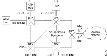
An example of a BPX switch network provisioned with BXM-622 cards is shown in Figure 5-1.
The BXM card group includes:
BXM cards may be configured to support either trunk (network) or port (service access) interfaces.
BXM cards are compliant with ATM UNI 3.1 and Traffic Management 4.0 including Abr VSVD and provide the capacity to meet the needs of emerging bandwidth driven applications.
For additional information on ATM Connections, refer to Chapter 21, Configuring ATM Connections.
The enhanced BXM-E card (version DX or EX) supports a higher connection density (32K) than either the legacy BXM or regular BXM-E cards. Both DX and EX versions have the same connection density, providing you with the ability to upgrade networks with the high connection density BXM-Es on trunk side, port side, or a combination of trunks and ports. You can smoothly upgrade BXM cards to BXM-E capabilities; see "Upgrade BXM to BXM-E Cards" in "Upgrade Information"
The BXM cards are designed to support all these service classes:
All software and administration firmware for the BXM card is downloadable from the BCC and is operated by the BXM on-board sub-system processor.
A BXM card set consists of a front and back card:
Any of the 12 general purpose slots can be used for the BXM cards. The same backcards are used whether the BXM ports are configured as trunks or lines. Table 5-1 and Table 5-2 list the available front and back card options for the BXM-T3/E3, BXM-155, and BXM-622.
| Front Card Model Number | No. of Ports | Cell Buffer (ingress/egress) | Connections per card | Back Cards |
|---|---|---|---|---|
T3/E3 (45 Mbps/34 Mbps) | ||||
BXM-T3-8 | 8 | 100K/130K | 16K | BPX-T3/E3-BC |
BXM-E3-8 | 8 | 100K/130K | 16K | BPX-T3/E3-BC |
BXM-T3-12 | 12 | 100K/230K | 16K | BPX-T3/E3-BC |
BXM-E3-12 | 12 | 100K/230K | 16K | BPX-T3/E3-BC |
OC-3/STM-1 (155.52 Mbps) | ||||
BXM-155-8 | 8 | 230K/230K | 16K | MMF-155-8 SMF-155-8 SMFLR-155-8 |
BXM-155-4 | 4 | 100K/230K | 16K | MMF-155-4 SMF-155-4 SMFLR-155-4 |
OC-12/STM-4 (622.08 Mbps) | ||||
BXM-622-2 | 2 | 230K/230K | 16K | SMF-622-2 SMFLR-622-2 SMFXLR-622-2 |
BXM-622 | 1 | 130K/230K | 16K | SMF-622 SMFLR-622 SMFXLR-622 |
| Back Card Model Number | No. of Ports | Description | Optical Range (less than or equal to) |
|---|---|---|---|
T3/E3 (45 Mbps/34 Mbps) | |||
BPX-T3/E3-BC | 8/12 | Universal T3/E3 backcard for | n/a |
OC-3/STM-1 (155.520 Mbps) | |||
MMF-155-8 | 8 | Multi-Mode Fiber | 2km |
MMF-155-4 | 4 | Multi-Mode Fiber | 2km |
SMF-155-8 | 8 | Single-Mode Fiber | 20km |
SMF-155-4 | 4 | Single-Mode Fiber | 20km |
SMFLR-155-8 | 8 | Single-Mode Fiber Long Reach | 40km |
SMFLR-155-4 | 4 | Single-Mode Fiber Long Reach | 40km |
OC-12/STM-4 (622.08 Mbps) | |||
SMF-622-2 | 2 | Single-Mode Fiber | 20km |
SMF-622 | 1 | Single-Mode Fiber | 20km |
SMFLR-622-2 | 2 | Single-Mode Fiber Long Range | 40km |
SMFLR-622 | 1 | Single-Mode Fiber Long Range | 40km |
Here are some of the major features of the BXM cards:
The BXM cards support the full range of ATM service types per ATM Forum TM 4.0.
Cbr Service:
Vbr Service:
Abr Service:
Ubr Service:
The minimum Sustainable Cell Rate (SCR) and Peak Cell Rate (PCR) of a connection supported by the BXM and UXM cards, including enhanced modes, was 50 cells per second (cps) or 19.2 Kbps. These values were set to maintain a policing accuracy with 1% when policing is performed on a BXM or UXM card. Because of this limitation, it was impossible to offer and differentiate connection services on a UXM or BXM at speeds less than 19.2 Kbps (50 cps).
In Release 9.3.0, the switch software supports connections with policing enabled and with SCR and PCR values as low as 12 cps on the BPX switch, with certain card limitations.
Use the dspcd command to determine if this feature is supported on a given slot.
Use the addcon command to set the minimum SCR and PCR values.
If these values are less than the minimum values supported on a given card, the command line interface will not allow you to set them until you have disabled policing. (A prompt will let you know about this limitation.)
Please refer to Table 5-1 for a list of cards that are supported by this feature and their performance specifications.
Policing must be disabled to support 6 cps and above for all BXM/UXM interface types.
Virtual ports support hierarchical egress traffic shaping at more than one level on a single UNI port, combining virtual path traffic shaping and associated virtual connections. This feature allows one or more Virtual Ports per Physical Port interface.
A maximum of 31 virtual ports are available per BXM card. Each port supports all Automatic Routing Management traffic types currently supported by physical ports. Up to 255 virtual ports are supported per BPX node (with BCC-4-128) and 144 ports (with BCC-3-64).
The Enhanced BXM cards improve the current BXM cards by delivering even more cost-effective ATM switching and traffic management. The Enhanced BXM cards come in EX and DX versions, both including these key feature enhancements:
| Model Number | Physical Interface | Number of Ports per Card | Ingress Cell Buffer (cells) | Egress Cell Buffer (cells) | Maximum Number of Connections per Card |
|---|---|---|---|---|---|
BPX-BXM-155-8DX | OC-3c/STM-1 | 8 | 512K | 512K | 32K |
BPX-BXM-155-8D | OC-3c/STM-1 | 8 | 256K | 256K | 16K |
BPX-BXM-155-4DX | OC-3c/STM-1 | 4 | 256K | 256K | 32K |
BPX-BXM-155-4D | OC-3c/STM-1 | 4 | 128K | 256K | 16K |
BPX-BXM-622-2DX | OC-12c/STM-4 | 2 | 512K | 512K | 32K |
BPX-BXM-622-2D | OC-12c/STM-4 | 2 | 256K | 256K | 16K |
BPX-BXM-622-DX | OC-12c/STM-4 | 1 | 256K | 256K | 32K |
BPX-BXM-E3-12EX | E3 | 12 | 256K | 512K | 32K |
BPX-BXM-E3-12E | E3 | 12 | 128K | 256K | 16K |
BPX-BXM-E3-8E | E3 | 8 | 128K | 128K | 16K |
BPX-BXM-T3-12EX | T3 | 12 | 256K | 512K | 32K |
BPX-BXM-T3-12E | T3 | 12 | 128K | 256K | 16K |
BPX-BXM-T3-8E | T3 | 8 | 128K | 128K | 16K |
The Enhanced BXM cards include features that can be enabled by future firmware and switch software:
Definitions
BPX: Broadband Packet Exchange is a WAN Business Unit's high-end ATM switch. BPX is a carrier-quality switch, with trunk and CPU hot standby redundancy.
BXM: Broadband Switch Module (BXM) are ATM cards for the BPX switch which use the Monarch chipset. Various different port configurations are supported by the BXM card: 8xDS3, 12xDX3, 4xOC3, 8xOC3, 1xOC12 or 2xOC12.
CLI: Command Line Interface
LCN: Each interface card in a BPX has a certain number of Logical Connection Number. A Logical Connection Number is used for each cross connect leg through the card in question.
VSI Virtual Switch Interface
Introduction
The enhanced BXM-E cards, model DX and EX support a higher number of LCNs (60K) than the legacy BXM or BXM-E model D and E. However, current SWSW caps the maximum number of LCNs that it can support to 32k; this means the total number of LCNs used by Autoroute connections and VSI connections cannot exceed the capped number of LCNs.
This project provides the BPX with the capability to support up to 60K LCNs for VSI connections while the maximum supported Autoroute LCNs remains unchanged at 32K.
Except otherwise stated, hereunder the term "legacy BXM" is used to stand for both legacy BXM and BXM-E model D or E, and the term "BXM-E" is used to represent DX or EX version of BXM-E which implies it supports 60K LCNs.
This document describes the feature content to support 60K LCN for VSI connections, and support hitless scaling from an active BXM-E configured in low VSI LCN density mode (32K) to higher VSI LCN density (60K) mode.
Purpose
The purpose of this project is to provides the customer with the ability to scale up their networks with the higher LCN density BXM-Es on trunk side, or port side, or a combination of ports and trunks. This high LCN density is only used for VSI connections.
Functional Description
Overview
This project is to provide the customer with the ability to scale up their VSI networks with the high connection density of BXM-Es on trunk side, or port side, or a combination of ports and trunks. This higher connection density is only used for VSI connections. It only requires the changes in SWSW, no firmware change is needed.
Currently, Autoroute and VSI connections share the same up boundary of LCN. When the BXM card comes up, it reports through 0X50 message about the "Number of Channels" and "Max Scheduler Channels". The Max Scheduler Channels is dependent on the BXM card type, e.g. regular BXM-E is 32K and enhanced BXM-E is 60K. The "Number of Channels" is dependent on the card type and Channel Statistics Level. The up boundary of combined Autoroute/VSI LCN is capped from "Number of Channels" in the current SWSW. All reserved 64 management channels are located at the top of this LCN space. Table 1 shows relationship for Enhanced BXM-E card about Channel Statistics Level, reported Number of Channels, Up boundary of LCN in current SWSW and the Management channel range.
Relationship of Channel Statistics Level, reported Number of Channels and Up boundary of LCN in current SWSW for Enhanced BXM-E card
Channel Stats Level Number of Channels Reported Up Boundary of LCN for AR+VSI in Current SWSW Management Channel Range
3 16K 16K-64 (16K-63) to 16K
2 32K 32K-64 (32K-63) to 32K
1 60K 32K-64 (32K-63) to 32K
0 60K 32K-64 (32K-63) to 32K
The management channels described in the table include:
1 APS channel,
12 LMI/ILMI channels,
12 IP relay channels,
15 VSI_IS channels
15 VSI_CVC channels
This project, via the execution of the cnfcdparm command as briefly described before, will move the management channels to the up end of 60K if the channel stats level is 0 or 1, change the up boundary of LCN for Autoroute and let VSI application use up to (60K-64) LCNs. Table 2 show the new channel relationship:
New channel relationship after this project in implemented
Channel Stats Level Number of Channels Reported Max LCN for Autoroute Max LCN for VSI Management Channel Range
3 16K 16K-64 16K-64 (16K-63) to 16K
2 32K 32K-64 32K-64 (32K-63) to 32K
1 60K 32K 60K-64 (60K-63) to 60K
0 60K 32K 60K-64 (60K-63) to 60K
The new feature does not affect service. No existing Autoroute and VSI connections are required to be deleted and added later on. No Autoroute and VSI traffic is disrupted when the user is deploying this feature.
The existing CLI command cnfcdparm is modified to support this feature. It is straightforward to execute this command. The successful execution of this command will configure the VSI LCNs to 60K and reprogram the management channels accordingly.
Functions
The following is the highlights of the features provided by this project:
Provides the capability to support 60K VSI LCNs on BXM-E cards while giving the option for the user to keep the previous 32K LCNs configuration.
Provides the hitless upgrading from an active BXM-E configured in 32K LCN mode to 60K VSI LCN mode.
Provides the capability to tell if a BXM-E card is already scaled up to support 60K VSI LCN.
Scope and Inter-dependencies
Scope
This feature will be available on the BPX 9.3.30 SWSW revision, the BXM-E card must support 60K LCNs.
Environment
This feature will require:
BPX Switch Software Release 9.3.30 which is targeted for Q2'01
BXM-E model EX or DX hardware with firmware revision supporting VSI.
BCC-4 controller card.
Usage
MPLS or PNNI user who wants to increase the number of VSI LCNs for a BXM-E slot to 60K need to upgrade their Switch Software to this release.
User who currently has legacy BXM cards need to upgrade those to BXM-E cards (model EX or DX) following the procedure for "Hitless Upgrade of BXM to BXM-E" [3]. This procedure is documented in release 9.3.00 which applies to this release and onward. The result of this upgrade is that the maximum number of LCNs will still be capped at 32K.
The user can use the CLI command cnfcdparm <slot> 2 Y to scale up the VSI LCN to 60K for the <slot>. If the <slot> has been scaled up to support 60K VSI LCN and the BXM-E card in the <slot> is in Standby status, the user can scale that slot back to support 32K LCN by using CLI command cnfcdparm <slot> 2 N.
Compatibility
This feature is to allow an easy way to configure the VSI LCN to 60 K for BXM-E card. There is no issue of incompatibility whatsoever in this project. However, this project introduces new scenarios of mismatch for BXM cards:
When a BXM-E slot, which has been configured to support 60K VSI LCN, is replaced by another card with lower channel density, mismatch will be declared.
When BXM-E cards are configured as y-redundancy or 1+1 APS, these Y-red pairs have been configured for 60K VSI LCN support, if one card of Y-red pairs is replaced by another card with lower channel density, mismatch will be declared.
Limits
Even though the BXM-E card can support up to 60K channels (LCNs), the maximum number of LCNs for Autoroute connections supported per BXM-E card is still capped at 32 K.
Since current BXM-E firmware does not support VSI partition shrinking, after VSI LCN expanding, the configured VSI connections will be kept at previous LCN space, and all additional LCNs will be forcefully allocated to the valid partitions on the card using the rules described in section 5.3.
After BXM-E slot is configured to support 60K LCN for VSI, customer cannot hitlessly reconfigure the card back to support previous 32K LCN. This is to protect the existing Autoroute and VSI connections which may have used the extra LCNs beyond previous LCN spaces. Please refer to Table 1 and 2. The only way to scale back is to down all lines and trunks on that BXM-E card first then use cnfcdparm to configure the slot back to support 32K LCNs.
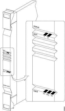
The BXM front panel has a three-section, multicolored "card" LED to indicate the card status. The card status LED is color-coded as indicated in Table 5-5. A three-section multi-colored "port" LED indicates the status of the ports.
A two-port BXM-622 is shown in Figure 5-2. An 8-port BXM-155 front card is shown in Figure 5-3. A 12-port BXM-T3/E3 is shown in Figure 5-4.
Types of failures are indicated by various combinations of the card status indicators as described in Table 5-6.
| Status | LED color | Status Description |
|---|---|---|
port | off | Trunk/line is inactive and not carrying data. |
| green | Trunk/line is actively carrying data. |
| yellow | Trunk/line is in remote alarm. |
| red | Trunk/line is in local alarm. |
card | green (act) | Card is on-line and one or more trunks/lines on the card have been upped. If off, card may be operational but is not carrying traffic. |
| yellow (stby) | Card is off-line and in standby mode (for redundant card pairs). May not have any upped trunks/lines. If blinking, indicates card firmware or configuration data is being updated. |
| red (fail) | Card failure; card has failed self-test and/or is in a reset mode. |
| act | stby | fail | Failure Description |
|---|---|---|---|
on | off | on | Non-fatal error detected; card is still active. |
off | on | on | Non-fatal error detected; card is in standby mode. |
off | blinking | on | Fatal error detected; card is in a reboot mode. |
on | on | on | Card failed boot load and operation is halted. |

The BXM backcards connect to the BXM front cards through the StrataBus midplane.
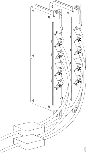
The BXM-622 is available in one or two port versions in either a single-mode fiber intermediate range (SMF) or a single-mode fiber long range (SMFLR) backcard. Connector information is listed in Table 5-7. A 2-port SMF card is shown in Figure 5-5.
| No. | Connector | Function |
|---|---|---|
1 or 2 | PORT | Two FC connectors per port, one each for the transmit and receive signal. |
The BXM-155 is available in four or eight port versions in a choice of multimode fiber (MMF), single-mode fiber intermediate range (SMF), or single-mode fiber long range (SMFLR) backcards. Connector information is listed in Table 5-8 and an 8-port SMF card is shown in Figure 5-6.
| No. | Connector | Function |
|---|---|---|
4 or 8 | PORT | One SC connector per port, accommodates both the transmit and receive signals. |
The BXM-STM1-4 is available in a four-port version that provides an electrical interface where the longer line lengths provided by the BXM optical backcards are not required. Connector information is listed in Table 5-9 and the backcard is shown in Figure 5-7.
| No. | Connector | Function |
|---|---|---|
4 | PORT | Two SMB connectors per port, one each for the transmit and receive signals. |
The BXM-T3/E3 is available in eight or twelve port versions. Connector information is listed in Table 5-10 and a 12-port T3/E3 card is shown in Figure 5-8.
| No. | Connector | Function |
|---|---|---|
8 or 12 | PORT | Two SMB connectors per port, one each for the transmit and receive signals. |
For SONET APS, card redundancy is provided by the use of two standard BXM front cards and two special backcards. The special backcards are the:
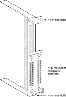
The two backcards are connected together by a BPX Redundant Backplane which mates with the BPX Midplane. The connectors are the same as those for the standard backcards. An APS backcard is shown in (Figure 5-10, and the BPX Redundant Backplane is shown in (Figure 5-11).


You can Y-cable the SMF-622 series backcards for redundancy by using the Y-Cable splitter shown in Figure 5-9. To configure the cards for Y-Cable redundancy, use the addyred command.
Automatic Protection Switching (APS) provides a standards-based line-redundancy for BXM OC-3 and OC-12 cards. The BXM OC-3 and BXM OC-12 cards support the SONET APS 1+1 and APS 1:1 standards for line redundancy. Line redundancy is provided by switching from the working line to the protection line.
The APS protocols supported by the BXM are listed in Table 5-11:
APS 1+1 | The APS 1+1 redundancy provides card and line redundancy, using the same numbered ports on adjacent BXM backcards. |
|---|---|
APS 1:1 | The APS 1:1 redundancy provides line redundancy, using adjacent lines on the same BXM backcard. |
APS 1:1 redundancy provides line redundancy only and is supported with the standard BXM OC-3 and OC-12 front and back cards.
APS 1+1 redundancy provides both card and line redundancy. It uses the standard BXM OC-3 and OC-12 front cards, but uses a special APS Redundant Frame Assembly and APS Redundant backcards.
A backcard is shown in (Figure 5-10). The APS Redundant Frame Assembly is shown in (Figure 5-11). Two redundant backcards are connected together by the APS Redundant Frame Assembly. The APS Redundant Frame Assembly with associated APS redundant backcards is inserted as a unit in two appropriate backcard slots.
Refer to Chapter 25, Configuring SONET Automatic Protection System, for additional information.

This functional description provides an overview of BXM operation.
This section is an overview of operation when the BXM card's ports are configured in port (access) mode for connection to customer equipment.
The ingress flow of ATM cells from CPE into a BXM port when the card is configured for port (access) operation is shown in Figure 5-12.
ATM cells from the customer premise equipment are:
For Abr cells, additional functions are performed by the SABRE Abr connection controller, including: VSVD, Foresight, and virtual connection queueing.
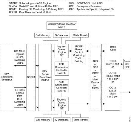
The egress flow of ATM cells out of the BXM when the card is configured for port (access) operation is shown in Figure 5-13.
ATM cells are:
1. Routed to the BXM-622 via the BPX Backplane/Stratabus from the BPX crosspoint switch,
2. Applied to the DRSIU,
3. To an egress queue per class of service, and
4. Served out to the SUNI (OC-3/OC-12) or Mux/Demux (T3/E3)
5. Which processes the ATM cells into frames,
6. Processes the cells from the ATM layer to the physical, and
7. On out to customer premise equipment connected to the ports on the BXM backcard.
For Abr cells, additional functions are performed by the SABRE Abr connection controller, including: VSVD, Foresight, and virtual connection queueing.

This section is an overview of the operation of the BXM when the card is configured in the trunk mode for connection to another node or network.
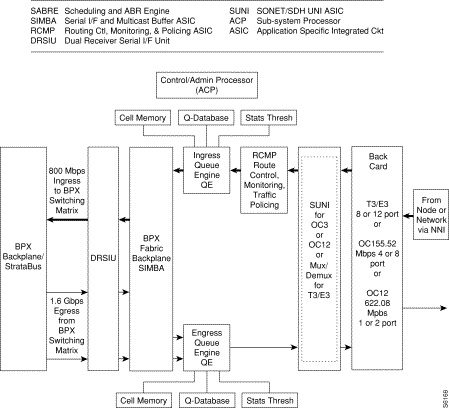
The ingress flow of ATM cells into the BXM when the card is configured for trunk operation is shown in Figure 5-14.
On ingress, ATM cells from a node or network are:
1. Processed at the physical interface level by the SUNI (OC-3/OC-12) or Demux/Mux (T3/E3)
2. Routed to applicable ingress slot queues
3. Served out to the BPX crosspoint switch via the BPX Backplane.
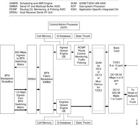
The egress flow of ATM cells out of the BXM when the card is configured for trunk operation is shown in Figure 5-15.
In egress, ATM cells are:
1. Routed to the BXM from the BPX crosspoint switch,
2. Applied to the DRSIU,
3. To an egress queue per class of service, and
4. Served out to the SUNI (OC-3/OC-12) or Demux/Mux (T3/E3).
5. The SUNI or Demux/Mux, as applicable, processes the ATM cells into frames,
6. Processing the cells from the ATM layer to the physical and
7. On out to the backcard trunk interface connecting to another node or network.
This section is a summary of the principal functions performed by the major functional circuits of the BXM.
The DRSIU provides a total egress capacity from the BPX switch fabric of 1.6 Gbps.
The SUNI ASIC implements the BXM physical processing for OC-3 and OC-12 interfaces. The SUNI provides SONET/SDH header processing, framing, ATM layer mapping and processing functions for OC-12/STM-4 (622.08 Mbps) or OC-3/STM1 (155.52 Mbps).
For ingress traffic, the BXM physical interface:
1. Receives incoming SONET/SDH frames,
2. Extracts ATM cell payloads, and
3. Processes section, line, and path overhead.
For egress traffic ATM cells are processed into SONET/SDH frames.
Alarms and statistics are collected at each level: section, line, and path.
The Demux/Mux and associated circuits implement the BXM physical layer processing for T3/E3 interfaces, processing functions for T3 at a 44.736 Mbps rate or E3 at a 34.368 rate. It provides:
Usage Parameter Control (UPC) is provided by the RCMP. Each arriving ATM cell header is processed and identified on a per VC basis. The policing function utilizes a leaky bucket algorithm.
In addition to UPC and traffic policing, the RCMP provides route monitoring and also terminates OAM flows to provide performance monitoring on an end-to-end per VC/VP basis.
Traffic policing and UPC functionality is in accordance with the GCRA as specified by ATM Forum's UNI 3.1 using dual leaky buckets.
In addition, two selective cell discard thresholds are supported for all queues for discard of CLP=1 cells should congestion occur.
The Scheduling and Abr Engine (SABRE) includes both VSVD and Foresight dynamic traffic transfer rate control and other functions:
The overall function of the queue engines is to manage the bandwidth of trunks or ports (UNI) via management of the ingress and egress queues.
In addition to the Abr VS queues, the ingress queues include 15 slot servers, one for each of 14 possible BPX destination slots, plus 1 for multicast operation. Each of the 15 slot servers contains 16 Qbins, supporting 16 classes of service per slot server.
In addition to the Abr VS queues, the egress queues include 32 Virtual Interfaces (VIs). Each of the 32 VIs supports 16 qbins.
This serial interface and multicast buffer ASIC provides:
The ACP performs these localized functions:
All basic configuration data on the card is copied to the battery backup memory (BRAM) on the card so that in the event of a power outage, the card will retain its main configuration.
Compliant to Bellcore GR-253-CORE
Alarms:
Performance Monitoring:
Statistics:
OAM
Compliant to Bellcore GR-253-CORE
Alarms:
Performance Monitoring:
Statistics:
Process Monitoring for ATM Header Cell Processing
Miscellaneous ATM Layer Statistics
| Back card | Source 1310 nm | Tx Power (dBm) Min Max | Rx Power (dBm) Min Max | Connection Type | Range (km) | ||
|---|---|---|---|---|---|---|---|
SMF (IR) | Laser 1310 nm | -15 | -8 | -28 | -8 | FC | 20 |
SMF (LR) | Laser 1310 nm | -3 | +2 | -28 | -8 | FC | 40 |
SMF (E) | Laser 1550 nm | -3 | +2 | -28 | -8 | FC | 40 plus |
| Back card | Source | Tx Power (dBm) Min Max | Rx Power (dBm) Min Max | Connection Type | Range (km) | ||
|---|---|---|---|---|---|---|---|
MMF | LED | -22 | -15 | -31 | -10 | SC | 2 |
SMF (IR) | Laser (Class 1) | -15 | -8 | -34 | -10 | SC | 20 |
SMF (LR) | Laser (Class 1) | -5 | 0 | -34 | -10 | SC | 40 |
![]()
![]()
![]()
![]()
![]()
![]()
![]()
![]()
Posted: Fri Jul 27 17:17:36 PDT 2001
All contents are Copyright © 1992--2001 Cisco Systems, Inc. All rights reserved.
Important Notices and Privacy Statement.