|
|

This chapter contains a description and configuration information for the SONET Automatic Protection System (APS) which may be used to provide line and card redundancy for BXM OC-3 and OC-12 cards:
Refer to the Cisco WAN Switch Command Reference for further information on configuration and monitoring commands.
To troubleshoot the APS configuration and operations, see Chapter 28, Troubleshooting.
Automatic Protection Switching (APS) configures a pair of SONET lines for line redundancy so that hardware automatically switches from a Working line to a Protection line when the Working line fails, and vice versa, within a specified period after an active line failure.
Each redundant line pair consists of a Working Line and a Protection Line. The concept of Working and Protection Lines is similar to the concept of Primary and Secondary Y Redundant cards. That is, the Working line is the logical line to which the user refers.
Left undisturbed, hardware performs line switching automatically. Upon detection of a Signal Fail condition (LOS, LOF, Line AIS or Bit Error Rate exceeding a configured limit) or a Signal Degrade condition (BER exceeding a configured limit), hardware switches from the Working Line to the Protection Line (assuming the Working line was the Active line and the Protection line is not in alarm).
If the "Revertive" option is enabled, (cnfapsln command), the hardware automatically switches back to the working line from the protection line after a configured time period called "Wait to Restore" (cnfapsln command) has elapsed. The working line must be in a clear state for this to occur. The revertive option is the default for APS 1:1 but not for APS 1+1.
Coordination between the two ends of the line is accomplished using the in-band protocol.
During setup, the commands addapsln, cnfcdaps, and cnfapsln are used to create the line-redundant pair. Also, appropriate front cards, back cards, and a special RDNT-BP daughter backplane are required for APS 1+1 configurations.
During operation, signal failure or signal degradation can cause APS "switchovers". A switchover is when the line that was active gives up control to its partner line. This partner line now becomes the "active" line, while the original active line becomes the "standby" line.
Automatic Protection Switching provides a standards based line-redundancy for BXM OC-3 and OC-12 cards. With Release 9.2, the BXM OC-3 and BXM OC-12 cards support the SONET APS 1+1 and APS 1:1 standards for line redundancy which is provided by switching from the working line to the protection line.
The working line is normally the active line, and the protection line is normally the standby line.
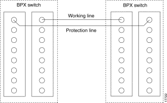
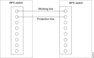
The APS 1+1 and APS 1:1 protocols that are supported by the BXM are listed in Table 25-1 and shown in Figure 25-2 and Figure 25-3, respectively. APS 1+1 Annex B has the same general layout as shown in Figure 25-2, except that the active line is called the primary, and the standby line is referred to as the secondary.
| Protocol | Description |
|---|---|
APS 1+1 | The APS 1+1 redundancy provides card and line redundancy, using the same numbered ports on adjacent BXM backcards. |
APS 1:1 | The APS 1:1 redundancy provides line redundancy, using adjacent lines on the same BXM backcard. |
APS 1+1 Annex B | The APS 1+1 Annex B redundancy provides 1+1 high-speed protection, which can be configured only for bi-directional, non-revertive protection switching. For Annex B, the active line is referred to as the "primary section" and the standby line is referred to as the "secondary section". Manual switching (switchapsln) is not allowed in the APS 1+1 Annex B implementation. |
SONET is defined across three elements, section, line, and path as shown in Figure 25-1 and described in Table 25-2. An advantage of this tiered approach is that management control can be exercised at each level, for example at the section level independent of the line or path level.
 |
Note APS on the BPX requires the use of single mode fiber, not multi-mode fiber, on both ends of the trunk. The PXM cards on any connected MGXs should also be single mode fiber. |

| Unit | Description |
|---|---|
Section | A section is the fiber optic cable between two active elements such as simple repeaters. The active element terminating these sections is called Section Terminating Equipment (STE). |
Line | A line is a physical element that contains multiple sections and repeaters and is terminated by line terminating equipment (LTE) at each end. |
Path | A path includes sections and lines and terminates at the customer premises equipment (CPE). |
Table 25-3 provides a cross-reference between OC-n optical carrier levels and the equivalent STS-n and SDH-n levels. It also includes the associated line rates.
| OC-n Optical Carrier | STS-n Synchronized Transport Signal | Line Rates (Mbps) | SDH-n Synchronized Digital Hierarchy | STM-n
Synchronous Transport Module |
|---|---|---|---|---|
OC-1 | STS-1 | 51.84 |
|
|
OC-3 | STS-3 | 155.52 | SDH-1 | STM-1 |
OC-12 | STS-12 | 622.08 | SDH-4 | STM-4 |
OC-48 | STS-48 | 2488.32 | SDH-16 | STM-12 |
SONET Automatic Protection Switching configures a pair of SONET lines for line redundancy so that the interface hardware automatically switches from a working line to the protection line or vice versa within a specified period after an active line failure.
However, you may use the switchapsln command to manually control switching. The last user switch request (switchapsln) per line pair is saved by switch software so that the APS can be configured correctly in the event of a node rebuild.
APS cards provide both front and backcard LED displays providing line and card status active and standby status.
The front card LED functions are listed in Table 25-4.
| LED | Description |
|---|---|
Card LED, Green | Active |
Card LED, Yellow | Inactive |
Port LED, Green | Line is active |
Port LED, Yellow | Line is standby |
The backcards used for APS 1+1 with front card redundancy have an LED which indicates whether the backcard can be pulled out for service replacement.
For example, all the lines on the card except one may be working properly and therefore the card needs to be replaced. The backcard LED functions are listed in Table 25-5.
| LED | Description |
|---|---|
Green | The card has at least one active line and may not be removed without affecting service. |
Yellow | The card has no active lines and may be removed. |
Red | Not used and not applicable. |
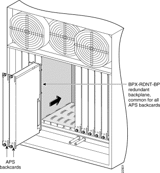
The APS 1+1 feature requires two BXM front cards, an APS redundant frame assembly, and two redundant type BXM backcards. The two redundant BXM backcards are plugged into the APS redundant frame assembly as shown in Figure 25-4. The types of available backcards are:
The types of redundant backcard and backplane sets required are:
The single backcards and mini-backplane can be ordered as spares. Their model numbers are:
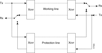
Traffic protected by APS 1+1 redundancy is carried via the working line and the protection line simultaneously (see Figure 25-5). Bridging is implemented such that the same payloads are transmitted identically over the working line as the protection line.
The receiver terminating the APS 1+1 has to select cells from either the working or protection line and be able to forward one consistent traffic stream. Since both working and protection line transport identical information, the receiving ends can switch from one to the other without the need for coordinating with the transmit end.
To set up APS, the addapsln command is used.
When no port on a BXM is configured for APS, each backcard of the pair may be used independently by independent front cards. The switch software disallows configuration of APS if independent usage is detected. There must be no active lines on the card that is selected to be the secondary card.
With previous card cages, because of the positioning of mechanical dividers, the APS card pairs can only be inserted in certain slots. These are slots 2 through 5 and 10 through 13. The mechanical dividers are located at slots 1 and 2, 5 and 6, 9 and 10, and 13 and 14.
With current card cages, this limitation is removed, and the APS card pairs can be located anywhere, except BCC cards slots 7 and 8, and ASM card slot 15.
An APS 1+1 redundant card pair must be in adjacent slots (2,3 or 4,5 and so on).
To implement the APS 1+1 redundancy:
Step 2 Then add APS
Ensure that these requirements are met:
The switching of the front cards is controlled by switch software under the Y-redundancy protocol. The switch software performs switching between the two cards in the event of a front card failure, front card downed, front card failing self-test, and so on.
You may add APS at any time after Y-redundancy is configured as long as the protection line is in the standby state. You may add APS even if lines and trunks are upped and the card is passing traffic.
 |
Note Normally when APS and card redundancy are implemented together, the term YRED really means card redundancy, as in this case there is no Y-cabling involved. An exception exists when the BXM is attached to a MGX 8220 (feeder shelf) or other device which does not support APS. In that case, Y-cables or straight cables may be used with APS. |
When APS is configured on a card pair, switch software checks to ensure that both cards match and support APS.
For APS 1+1 redundancy, the same numbered ports on adjacent BXM backcards are used. The maximum number of connections supported does not change, as the complete connection capability of the cards is available.
 |
Note Using only one front card and two backcards is not a valid configuration when adding APS capability, and the APS alarm capability is reduced when the standby card is not available. |
 |
Note Entering switchcdred or switchyred execute the same command. The newer name is switchcdred which replaces switchyred, but switchyred may still be used for those familiar with that command. |
The switchcdred (switchyred) command can be used to switch between an active and standby front card in an APS 1+1 configuration. For example, you might want to do this to test the standby front card.
Following a switchcdred (switchyred), or active card reset, the BXM card is sent a message from switch software to have it perform an APS switch to align itself with the last user switchapsln switch request.
If the last user request is "clear", full automatic APS switching is in effect with the working line in the active state by default. When there is no last user switch request to switch any particular line (that is, protection line), the working line becomes active.
 |
Note In the APS 1+1 configuration, if the protection line is active and the last user request is "clear," a switchdred will cause the working line to be active if there is no line condition on working line. When APS 1+1 comes up, it will come up on the working line if the working line is clear. When a switchcdred is issued, the active card also comes up on the working line if the working line is clear and there is no user request. In the case where the working line is in alarm or there is a user request to switch to the protection line (switchapsln), the card will first come up on the working line. Then the card will detect the alarm or the user request and switch to the protection line. |
 |
Note In the APS 1+1 configuration, if the last user request was a W -> P switch, then dsplog will log a W -> P switching event when a switchcdred is issued. On a switchcdred, the newly active card comes up on working line first. Then it responds to a user request to switch from working to protection by switching to the protection line and sending an event notification to that effect. The event notification can be seen in the event log by using the dsplog command. |
 |
Note It may be necessary to perform a switchcdred (switchyred) command after performing a service switch with the switchapsln command so that the backcard that the service switch selects has its associated front card active. |
With APS 1+1, when repetitive switchapsln commands are issued, up to two in a row can be executed sequentially, when alternating between options 3 and 4 (forced switch), or 5 and 6 (manual switch), but no more. Attempts to execute a third switchapsnln will not succeed, and the following error message is displayed:
"Cannot request manual W->P when manual P->W switch in progress"
If you wish to perform repetitive switchapsln commands, you should issue a clear switch between each W-P, P-W pair of commands, for example:
switchapsln 2.1 1
This an example of configuring APS 1+1 redundancy:
Step 2 Ensure that lines are connected, for example on port 1 of BXM card in slot 2 and port 1 of BXM card in slot 3.
Step 3 Execute these commands and verify chan half= no, and standard= GR-253 (default)
cnfcdaps 2.1 N 1
cnfcdaps 3.1 N 1
Step 4 Execute the following command, for example, for redundant line on port 1 for BXM OC-3 cards and APS backcards in slots 2 and 3 of the BPX:
addcdred 2 3
Step 5 addapsln 2.1 3.1 1 {addapsln<slot.port> <slot.port> <1|2|3|..>
 |
Note The last entry, "1", in the addapsln command specifies the type of APS, in this example APS 1+1. |
Step 6 cnfapsln 2.1
Step 7 upln 2.1 {or uptrk, as applicable
The APS 1:1 feature provides port and line redundancy for a single BXM front card and associated OC-3 or OC-12 redundant backcard.
There is no new hardware required to support APS 1:1. A single front card with a standard backcard is used.
Two adjacent lines on the same card are used. The maximum number of connections supported by a non-enhanced BXM card is reduced by half for APS 1:1 operation. Using enhanced BXM cards, the number of available connections is not decreased.
Similarly to APS 1+1, SONET APS 1:1 requires that for every working line, there must exist a redundant protection line (see Figure 25-6). However, unlike the 1+1 case, traffic protected by the redundancy must be carried on the protection line only when a failure occurs on the working line. In the case of no failure, the protection line can transport idle traffic, `same' traffic as working line, or extra traffic. Because the protection line is not guaranteed to carry real traffic until the transmit end is informed of the failure and switches, this coordination between the equipment at both ends is more complex.
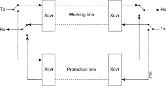
To set up APS, the addapsln command is used.
APS 1:1 cannot be configured on cards already configured for YRED. They cannot be configured concurrently. Use APS 1 + 1 instead.
APS 1:1 configuration requires that the user add the APS configuration to a line before upping the line.
APS 1:1 configuration requires that the user down a line prior to deleting the APS configuration on the line.
APS 1:1 can only be configured for bi-directional operation and revertive switching.
The redundant lines must be adjacent. In addition, the lines which may be paired are:
Either of the two lines may be designated as working line and the other as the protection line.
The switching of the working and protection lines is controlled by BXM firmware/hardware under the APS protocol.
The BPX firmware/hardware performs switching between the protection and working lines in the event of a line or port failure.
The user may add APS as long as the working and protection line are in the standby state. Lines and trunks can only be upped after APS 1:1 is added.
This is an example of configuring APS 1:1 redundancy:
 |
Note Before configuring for APS 1:1 redundancy, all card connections must be deleted using the delcon command |
 |
Note The last entry, "2", in the addapsln command specifies the type of APS, in this example APS 1:1. |
Step 2 Execute cnfcdaps and verify chan half= yes (not default), and standard= GR-253 (default)
cnfcdaps 3.1 Y 1
Step 3 addapsln 3.1 3.2 2 {addapsln<slot.port> <slot.port> <1|2|3|4|5>
Step 4 upln 3.1 {or uptrk, as applicable
The APS 1 +1 Annex B feature is similar to the APS 1+1 feature, with the main difference being that APS 1+1 Annex B redundancy only can be configured for bi-directional operation and non-revertive switching.
APS 1 + 1 Annex B can be configured only for bi-directional operation and non-revertive switching on a line.
 |
Note In non-revertive switching, to avoid data loss, a line is not automatically switched back to active after a failure is corrected. |
The following is an example of configuring APS 1+1 redundancy:
Step 2 Ensure that lines are connected, for example port 1 on BXM in slot 1 and port 1 on BXM in slot 2.
Step 3 Execute the following commands and verify chan half= no, and standard= GR-253 (default)
cnfcdaps 1.1 N 1
cnfcdaps 2.1 N 1
Step 4 Execute the following command, for example, for redundant line on port 1 for BXM OC-3 cards and APS backcards in slots 1 and 2 of the BPX:
addcdred 1 2
Step 5 addapsln 1.1 2.1 3 {addapsln<slot.port> <slot.port> <1|2|3|..>
 |
Note The last entry, "3", in the addapsln specifies the type of APS, in this example APS 1 + 1, Annex B. |
Step 6 cnfapsln 1.1
Step 7 upln 1.1 {or uptrunk, as applicable
The test commands addlnloclp and addlnrmtlp may affect service even when APS is configured. In all APS configurations, if the working line is looped, both lines will be looped and traffic disrupted.
When adding an APS 1+1 line or trunk by using addapsln, if the working slot's paired redundant slot is not a legal protection slot, or if firmware cannot determine what the paired slot is, an invalid slot pairing exists and one of the following two messages will be displayed:
"Protection card specified by user does not match HW."
"Working card specified by user does not match HW."
You can display the redundant card information by using the dspcd command under the "Backcard Installed" heading. For example, if a redundant pair is configured with a primary slot of 2 and a secondary slot of 3, the dspcd 2 command should display "RedSlot: 3", and the dspcd 3 command should display "RedSlot: 2".
This is an example of dspcd 2:
swwye     TN       silves        BPX8620      9.3 March 9  2000

Detailed Card Display for BXM-155 in slot 2

Status:          Active
Revision:        DDA                 Backcard Installed
Serial Number    652774                Type:          LM-BXM
Fab Number       28-2158-02            Revision       EW
Queue Size       228300                Serial Number  1..1...
Support: 4 Pts, OC-3, FST,  VcShp       Supp: 4 Pts, OC-3, SMF, RedSlot:3
Support: VT, ChStLv 2, VSIlvl 2
Support: APS (FW, HW1+1)
Support: OAMLp, TrfcGen
#Ch: 8128, PG[1] :8123
#Sched_Ch:16284

Last Command: dspcd 2
The possible conditions which may cause/prevent a switch are listed in Table 25-6. The list is arranged starting from highest precedence and ending with lowest precedence. Refer to the Cisco WAN Switching Command Reference for further description and information.
| APS K1 Command Precedence |
|---|
Lock out of Protection |
Forced Switch |
Signal Fail |
Signal Degrade |
Manual Switch |
Wait To Restore |
Reverse Request |
Do not Revert |
No Request |
Commands to support APS are listed in Table 25-7, and defined in more detail in the Cisco WAN Command Reference where you will find thorough information on each of these commands, as well as other commands not listed here.
| Command | Description |
|---|---|
| New Commands Added for Management of APS | |
cnfcdaps slot | Sets APS options on the card. |
addapsln slot1.port1 slot2.port2 protocol | Adds APS. |
delapsln slot.port | Deletes APS. |
dspapsln | Displays status of APS line pairs. |
switchapsln slot.port (option 1...6, S) | Controls the APS user switching interface. |
cnfapsln slot.port | Configures the APS parameters on a line. |
| New Commands for Card Redundancy for APS 1+1 | |
addcdred | Adds redundancy across two cards. |
dpscdred | Display redundant cards. |
delcdred | Deletes redundancy configuration for cards. |
switchcdred | Switches active and redundant cards. |
| Commands modified for use with APS | |
cnfbkcd | Modified to APS options. |
dspalms | Added row for "APS Alarms" which lists Minor and Major APS alarms. |
dspcd | Displays front and backcard APS attributes. For the front card, displays that card supports APS 1+1 and APS 1:1. For the back card, displays if backcard is a redundant backcard, and if so, the slot number of the redundant backcard. Also, displays APS mismatch conditions. |
dspsv3 | Modified to display APS alarms pending. |
dsplog | Displays APS alarms. |
addyred | Modified to prevent invalid configurations when combined with APS. |
delyred | Modified to prevent invalid configurations when combined with APS. |
![]()
![]()
![]()
![]()
![]()
![]()
![]()
![]()
Posted: Fri Jul 27 17:51:52 PDT 2001
All contents are Copyright © 1992--2001 Cisco Systems, Inc. All rights reserved.
Important Notices and Privacy Statement.