|
|

Table Of Contents
Calculating Transmit and Receive Rates on IMA Lines
Setting Up Lines
A circuit line is the physical line that carries data, voice, Frame Relay, or ATM traffic between an IGX or BPX node and customer premises equipment (CPE). Each piece of customer premises equipment is attached to a node through a circuit line. After a card has been "upped" with the upcd command, a circuit line on that card can be "upped" and configured.
This chapter:
•
Describes input circuit line formats
•
•
•
Note
Table 5-1 shows input line formats. Table 5-2 shows the permissible card combinations for CPE-to-IGX lines.
Setting Up a Circuit Line
Frame Relay, data, and voice connections require an active line. Use the commands in the following steps to establish a line. The card must be in either the active or standby state before you enter these commands.
Step 1
Step 2
Step 3
The upln and cnfln commands establish the general parameters for the line but do not establish specific Frame Relay, data, or voice parameters. Refer to applicable chapters for details on a particular service. For example, Data Connections describes specific commands for data connections, and Frame Relay Connections describes specific commands for Frame Relay connections.
Setting Up an IMA Line
Inverse Multiplexing over ATM (IMA) allows you to group physical T1 or E1 lines to form a logical line, also known as an IMA line. By bundling smaller lines together to form an IMA line, you enlarge the traffic bandwidth on your network without upgrading to a higher speed service, such as T3/E3. Therefore, you're
the access lines you already have instead of replacing them. The IMA line feature is compliant with ATM Forum Standard version 1.0, allowing UXM IMA trunks to interoperate with other vendor equipment.
IMA line characteristics are as follows:
•
•
•
•
–
–
•
•
•
•
•
To configure an IMA line:
1.
upln <slot>.<group-members>
Where group-members are the physical lines composing an IMA group; for example:
upln 10.1,3,6,8 adds the primary link 10.1 and the non-consecutive physical lines 10.3, 10.6, and 10.8. When you use other commands, such as dnln or cnfln, this IMA group is known by the primary link, 10.1.
upln 10.5-7,2-3 adds the primary link 10.5 and the physical lines 10.5, 10.6, 10.7, 10.2, and 10.3. When you use other commands, such as dnln or cnfln, this IMA group is known by the primary link, 10.5.
2.
3.
To modify an IMA line:
1.
2.
3.
To view IMA line information:
1.
Clear LN 10.1 OKClear LN 10.1 ActivatedClear PHYSLN 10.1 OKClear PHYSLN 10.1 ActivatedFollowing a dnln 10.1 command, the dsplog command shows:
Clear LN 10.1 DeactivatedClear PHYSLN 10.1 DeactivatedFollowing an Inverse Mux Failure for an IMA group with three lines in the group, the dsplog command shows:
Major LN 10.2(3)Inverse Mux FailureMajor PHYSLN 10.4 Inverse Mux FailureMajor PHYSLN 10.3 Inverse Mux FailureMajor PHYSLN 10.2 Inverse Mux Failure2.
dsplns 3.1System Response: 3.1 (4) OKIMA line failure is indicated by the error message Inverse Mux Failure. An Inverse Mux Failure can be triggered by:
–
–
–
–
–
3.
4.
sw225 TN StrataCom IGX 16 9.3.00 Jun 19 1999 13:39 PSTPort: 7.2 [ACTIVE ]IMA Port Group: 2-5Interface: E1-IMA CAC Override: EnabledType: UNI %Util Use: DisabledSpeed: 13433 (cps)SIG Queue Depth: 640Protocol: NONELast Command: dspport 7.25.
sw225 TN StrataCom IGX 16 9.3.00 Jun 19 1999 13:39 PSTPort configuration for ATM 8Port Chan Speed Interface State Protocol Type1 1 4528 (cps) E1-IMA ACTIVE NONE UNI2 2 4528 (cps) E1-IMA INACTIVE NONE UNI3 3 4528 (cps) E1-IMA INACTIVE NONE UNI4 4 4528 (cps) E1-IMA INACTIVE NONE UNI5(3) 5-8 54000 (cps) E1-IMA ACTIVE NONE(IMA) UNITo configure and view IMA statistics:
1.
2.
3.
Calculating Transmit and Receive Rates on IMA Lines
The port rate of an IMA line is the sum of all physical lines less the IMA protocol overhead. The overhead is calculated as:
•
•
When an IMA group is reconfigured, the IMA line bandwidth is readjusted automatically because of the change in the total number of links.
Please refer to Table 5-3 for composite port speeds.
Flow Diagrams for Line Setup
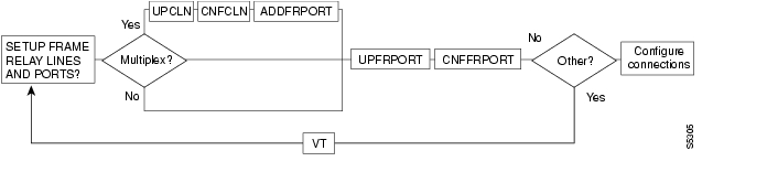
Figure 5-1, Figure 5-2, Figure 5-3, and Figure 5-4 show the command sequence for setting up lines for voice, serial data, Frame Relay, and ATM, respectively. A yes/no decision branch for "Other Side?" and the vt command in the sequence indicates command sequences on local and far nodes. Multiplex refers to channelized streams.
Figure 5-1 Setting Up Voice Lines
Figure 5-2 Setting Up Data Lines
Figure 5-3 Setting Up Frame Relay Lines
Figure 5-4 Setting Up ATM Lines
List of Commands
Table 5-4 shows the full command name and starting page for each line command description.
cnfcassw
Configures a UVM to convert channel associated signaling (CAS) and dual-tone multi-frequency (DTMF) tones to common channel signaling (CCS) call control messages. This conversion is necessary for voice networks in which a Voice Network Switch (VNS) uses SVCs to route calls from a CAS-based PBX through a WAN. Model B or later firmware on the UVM is necessary.
Before you can execute cnfcassw, note the following:
•
•
•
•
Full Name
Configure CAS switching
Syntax
cnfcassw <line> <mode> <CCS type> <CAS type> <conn type> <country code>
<interdigit timeout> <tone level> <DTMF duration> <idle pattern> <parameters 6-18>
Note
Related Commands
dspln, dsplncnf
Attributes
Example 1
cnfcassw 5.1
Description
Configure port 1 of the UVM in slot 5 to support CAS switching.
System Response
sw175 TN SuperUser IGX 8420 9.2 Sep. 17 1998 06:11 PSTLine 5.1 CAS Switching Parameters=> CASSW mode [OFF] Parm 11 [00] (H)CCS Type [ 1] (D) Parm 12 [00] (H)CAS Type [ 1] (D) Parm 13 [00] (H)Conn Type [a32 ] Parm 14 [00] (H)Country code [00] (H) Parm 15 [00] (H)Interdigit TO [05] (H) Parm 16 [00] (H)Tone level [00] (H) Parm 17 [00] (H)DTMF duration [0C] (H) Parm 18 [00] (H)Idle pattern [54] (H)Parm 6 [00] (H)Parm 7 [00] (H)Parm 8 [00] (H)Parm 9 [00] (H)Parm 10 [00] (H)This Command: cnfcassw 5.1Enter mode: Pbx/Server/Off (o):
cnfln
Configures a line to be compatible with the device to which it connects. The cnfln command applies to voice, data, Frame Relay, and ATM, and IMA lines. See Table 5-3 for a list of the front and matching back cards. Because of the variety of line types and characteristics, the parameters section of this description has three tables to describe the parameters. The system automatically presents the correct options on the command line for each line type. If a parameter is not applicable to a card type, the system displays the parameter in half-tone or the value field of that parameter with dashed lines. Table 5-5 describes the parameters for voice, data, and Frame Relay parameters. Table 5-6 describes the parameters for the ATM Line Module (ALM/A). Table 5-7 describes the parameters for the ASI line card (BPX node). Table 5-8 describes the ATM parameters for the UXM card (IGX node). describes the IMA parameters for the UXM card (IGX node).
For an ALM/A, the cnfln command lets you configure the receive rate and header type and enable payload scrambling. For more details on the features and configurable parameters of the ALM/A, refer to the Cisco IGX 8400 Series Reference and the Cisco IGX 8400 Series Installation manuals. Note that, although the cnfln display shows the transmit rate, you cannot configure it because the ALM/A transmit rate is always the maximum line rate.
For an IMA line, you can add or delete links in an IMA group, or specify the number of retained links for an IMA configuration. By default, the number of retained links is the same as the number of lines grouped together when the IMA group is created; for example:
upln 3.1-4
Results in 4 lines in an IMA group with 4 retained links. If one link fails, the IMA line fails. Using the cnfln command, you can change the parameter "Retained Links" to a lesser number, for example, 3. Therefore, if one of the lines failed, the IMA line could remain active.
For more information about commands related to IMA lines, refer to List of Commands.
Note
Full Name
Configure line
Syntax
cnfln <line> <parameters>
Syntax for IMA
cnfln <slot>.<primary link>
Related Commands
dspln, dsplncnf, dsptsmap, dnln, upport, dspport, dspports
Attributes
Example 1
cnfln 14
Description
Configure voice line 14.
System Response
alpha TRM YourID:1 IGX 8420 9.2 Aug. 23 1998 09:55 PSTCLN 14 Configuration T1/24 CDP slot: 13Loop clock: --Line framing: --coding: --CRC: --recv impedance: --E1 signalling: --encoding: --T1 signalling: --cable type: --length: --56KBS Bit Pos: --pct fast modem: --Last Command: cnfcln 14Next Command:Example 2
cnfcln 7 n 2
Description
Configure a Frame Relay T1 line for the following options: no loop clock and a receive impedance of 75 ohms.
System Response
alpha TRM YourID:1 IPX 16 9.2 Aug. 23 1997 09:55 PSTCLN 14 Configuration T1/24 FRPslot: 13Loop clock: --Line framing: ESFcoding: ZCSCRC: --recv impedance: --E1 signalling: --encoding: --T1 signalling: --cable type: ABAMlength: 0-133 ft.56KBS Bit Pos: --pct fast modem: --Last Command: cnfcln 7 n 2Next Command:Example 3
cnfln 4.2 7F 0 N
Description
Configure ASI port 4.2 with an idle code 7F and without payload scrambling.
System Response
ca19 VT SuperUser BPX 8620 9.2 Aug. 23 1998 19:11 GMTLN 4.2 Configuration T3 [96000 cps] ASI-T3 slot:4Loop clock: -- Idle code: 7F hexLine framing: --coding: --CRC: --recv impedance: --E1 signalling: --encoding: -- cable type:T1 signalling: -- length: 0-450 ft.HCS Masking: YesPayload Scramble: No56KBS Bit Pos: --pct fast modem: --Last Command: cnfln 4.2 7F 0 NNext Command:Example 4
cnfln 12
Description
Configure the ALM/A in slot 12.
System Response
reach TN SuperUser IGX 8420 9.2 July 22 1998 12:39 PDTLN 12 Config T3/3 [452 cps] ALM slot: 12Transmit Line Rate: 96000 cpsReceive Line Rate: 452 cpsHeader Type: VCCPayload Scramble YesLast Command: cnfln 12 452 vcc yNext Command:Example 5
cnfln 10.1 N D4 ZCS AB 4 20 _
Description
Configure line 1 on the UVM in slot 10 with no loop clock, D4 framing, Zero Code Suppression coding, AB T1 signalling, and 20 percent expected channel utilization by a high speed modem.
System Response
sw176 TN SuperUser IGX 8420 9.2 Sep. 15 1998 13:37 PSTLN 10.1 Config T1/24 UVM slot: 10Loop clock: NoLine framing: D4 cnfg: Externalcoding: ZCS slot.line: --CRC: -- CAS-switching: PBX-endrecv impedance: -- SVC-Caching : OnE1/J1 signalling: --encoding: u-lawT1 signalling: ABcable type: ABAMlength: 0-133 ft.56KBS Bit Pos: msbpct fast modem: 20This Command: cnfln 10.1 N D4 ZCS AB 4 20 _Turn on SVC-Caching (Y):This release has added a prompt to configure a UVM line for SVC Caching. It is also supported on CVM lines on the IPX. The SVC Caching feature speeds up call setup for most VNS controlled calls by avoiding some of the call setup/tear-down operations when a call originates or terminates.
Refer to the VNS Installation and Configuration Manual for more information on SVC Caching.
Example 6
cnfln 5.1 1-15,17-31 1-8 6 200 N 54 Y Y N
Description
Configure the number of retained links from the default (8 for this configuration) to 6.
sw225 TN StrataCom IGX 8420 9.3.l3 Feb. 2 2000 10:14 GMTLN 5.1(8) Config E1/238 UXM slot:10Line DS-0 map: 1-15,17-31IMA Group Member(s): 1-8Retained links: 6IMA Protocol Option: EnabledIMA Max. Diff. Dly: 200 msec.IMA Clock Mode: CTCLoop clock: NoLine coding: HDB3Line CRC: YesLine recv impedance: 75 ohmIdle code: 54 hexHCS Masking: YesPayload Scramble: YesVC Shaping: NoThis Command: cnfln 5.1 1-15,17-31 1-8 6 200 N 54 Y Y NNext Command:
cnfrsrc
Use the cnfrsrc command to partition resources (ports and trunks) for Automatic Routing Management PVCs, VSI-MPLS (Multiprotocol Label Switching), or PNNI SVCs. (If you want to configure resources for a VSI-MPLS controller or PNNI SVCs, refer to cnfrsrc in the "VSI Commands" chapter for more information specific to configuring VSI options.)
Note
You can configure a virtual trunk to be dedicated to VSI or to Automatic Routing Management. You cannot configure a virtual trunk for both VSI and Automatic Routing Management.
This command was introduced in Release 9.1 to support physical trunks. It has been extended to support virtual trunks. After VSI has been enabled, the virtual trunk becomes a "dedicated" VSI virtual trunk. Note that if the trunk has already been added or if the VPI value has not been configured, you will not be able to configure the VPI value. (Switch software will block you from doing so.)
Configurable resources (using cnfrsrc) are:
•
•
•
•
•
•
•
•
•
•
•
•
The resources that you can currently configure are the number of connection IDs (conids) and the trunk bandwidth. You use the cnfrsrc command to configure the cell rate and number of connections on a BXM card only. (You cannot use the cnfrsrc command on the IGX.)
You configure all port and trunk attributes with cnftrk, cnftrkparm, or cnfrsrc. Note that when you change a physical port attribute, you will be notified that all the logical (physical and virtual) trunks on the port are affected.
Note
Full Name
Configure resource
Syntax
cnfrsrc <slot>.<port> <maxpvclcns> <maxpvcbw> <partition> <e/d> <minvsilcns> <maxvsilcns> <vsistartvpi> <vsiendvpi><vsiminbw> <vsimaxbw>
Related Commands
dsprsrc
Attributes
Example 1
cnfrsrc 11.2 256 96000 y 1 e 0 0 1 1 0 0
Description
Configure resource partitions on card slot 11, port 2, to use Automatic Routing Management PVCs.
System Response
sw98 TN SuperUser BPX 8600 9.2.0r Apr. 4 1998 16:40 PSTPort/Trunk : 11.2Maximum PVC LCNS: 256 Maximum PVC Bandwidth:96000Min Lcn(1) : 0 Min Lcn(2) : 0Partition 1Partition State : EnabledMinimum VSI LCNS: 0Maximum VSI LCNS: 0Start VSI VPI: 1End VSI VPI : 1Minimum VSI Bandwidth : 0 Maximum VSI Bandwidth : 0Last Command: cnfrsrc 4.1 256 26000 1 e 512 7048 2 15 26000 100000Next Command:
Table 5-11 cnfrsrc—Parameters
slot.port
Specifies the BXM card slot and port number.
Maximum PVC LCNs
The maximum number of LCNs allocated for Automatic Routing Management PVCs for this port. The range is 1 to 256; 256 is the default. For trunks, there are additional LCNs allocated for Automatic Routing Management that are not configurable.
You can use the dspcd <slot> command to display the maximum number of LCNs you can configure using the cnfrsrc command for the given port. For trunks, configurable LCNs represent the LCNs remaining after the BCC has subtracted the networking LCNs needed. A trunk has 270 networking LCNs, or channels.
For a port card, a larger number is shown, as compared with a trunk card. This is because a trunk uses 270 networking LCNs, as compared with a port card, which uses no networking LCNs.
Setting this field to "0" would disable Automatic Routing Management PVCs on the specified port.
Note that you must specify a value greater than 0 for the Maximum PVC LCNs, Maximum PVC Bandwidth, and Maximum VSI LCNs parameters. Otherwise, you will not be able to create any Automatic Routing Management PVC connections on a BXM card. Also, if these parameters do not have values greater than 0, you will be unable to change the connection channel amount when you configure the BXM trunk using cnftrk.
Maximum PVC Bandwidth
Specifies the maximum bandwidth of the port allocated for Automatic Routing Management use. The range is 0 to 352207; 0 is the default. You can configure the Maximum PVC Bandwidth value for ports, but not for trunks.
Note that you must specify a value greater than 0 for the Maximum PVC LCNs, Maximum PVC Bandwidth, and Maximum VSI LCNs parameter. Otherwise, you will not be able to create any Automatic Routing Management PVCs on the BXM card.
Configure Partition
Answer yes or no to begin configuring resources for the partition. If you enter "n" for No, you will not be prompted to configure any VSI options. If you are configuring Automatic Routing Management PVCs, enter "n" for No.
If you want to configure VSI options, enter "y" for yes, and you will be prompted to enter the rest of the cnfrsrc parameters, which are related to configuring VSI (such as a VSI MPLS controller or a PNNI controller). Refer to the cnfrsrc command in "VSI Commands" chapter for more information on VSI-related options.
Partition ID
Specifies the ID number of the partition; 1 is the default. Always use 1 in Release 9.1. In this release, you can use 2. (The range of 0 to 255.)
Enable Partition
Answer yes or no to enable your configured partition.
Minimum VSI LCNs
The minimum number of LCNs guaranteed for this partition. The range is 1 to 256; 0 is the default. The VSI controller guarantees at least this many connection endpoints in the partition, provided there are sufficient free LCNs in the common pool to satisfy the request at the time the partition is added. When a new partition is added or the value is increased, it may be that existing connections have depleted the common pool so that there are not enough free LCNs to satisfy the request. The BXM gives priority to the request when LCNs are freed. The net effect is that the partition may not receive all the guaranteed LCNs (min LCNs) until other LCNs are returned to the common pool.
You can increase this value dynamically when there are enough unallocated LCNs in the port group to satisfy the increase.
You may not decrease the value dynamically. All partitions in the same port group must be deleted first and reconfigured in order to reduce this value.
To avoid this deficit condition, which could occur with maximum LCN usage by a partition or partitions, it is recommended that all partitions be configured ahead of time before adding connections. Also, it is recommended that all partitions be configured before adding a VSI controller using the addshelf command.
Maximum VSI LCNs
The total number of LCNs the partition is allowed for setting up connections. The min LCNs is included in this calculation. If max LCNs equals min LCNs, then the max LCNs are guaranteed for this partition.
Otherwise, (max - min) LCNs are allocated from the common pool on a FIFO basis.
If the common pool is exhausted, new connection setup requests will be rejected for the partition, even though the maximum LCNs has not been reached.
You may increase this value dynamically when there are enough unallocated LCNs in the port group to satisfy the increase.
You may not decrease the value dynamically. All partitions in the same port group must be deleted first and reconfigured in order to reduce this value.
Different types of BXM cards support different maximum values. If you enter a value greater than the allowed maximum, a message is displayed with the allowable maximum value.
Note that you must specify a value greater than 0 for the Maximum VSI LCNs, Maximum PVC Channels, and Maximum PVC Bandwidth parameters. Otherwise, you will not be able to add any connections on a BXM card.
Start VSI VPI
By default the TSC (for example, the 7200 or 7500 series router) will use either a starting VSI VPI of 1 or 2 for tag switching, whichever is available. If both are available, a starting VSI VPI of 1 is used. The VPI range should be 2-15 on a BPX 8620 VSI. The VSI range for tag switching on the BPX 8620 is configured as a VSI partition, usually VSI partition number 1. VSI VPI 1 is reserved for Automatic Routing Management PVCs. (This restriction applies only to trunks, not to ports. For a port, you can use any VPI value.) For a port UNI, the VPI range is 1 to 255. For a port NNI, the range is 1 to 4095. For trunks that do not have Automatic Routing Management configured, the VPI ranges are the same as for ports.
The VSI partition for tag switching should start at VPI 2. If VPI 2 is not to be used, you can use the tag switching VPI interface configuration on the TSC to override the defaults.
For trunks with Automatic Routing Management configured, the range is 2 to 4095. Always set to 2 for trunks.
End VSI VPI
Two VPIs are sufficient for Release 9.1, although it may be advisable to reserve a larger range of VPIs for later expansion, for example, VPIs 2-15.
The range is the <Start VSI VPI > value to 4095.
Minimum VSI Bandwidth
The minimum port bandwidth that can be used by this partition in cells/second.
The range is 0 to <Maximum Line Rate>. For example, the OC-3 line rate is 352207; 0 is the default.
Maximum VSI Bandwidth
The maximum port bandwidth that can be used by this partition. This value is used for VSI QBins bandwidth scaling.
The range is 0 to <Maximum Line Rate>. For example, the OC-3 line rate is 352207; 0 is the default.
dnln
Deactivates ("downs") a line. After dnln executes, the line no longer generates framing, and no statistics are gathered. Before you deactivate a line, use delcon to remove all connections on the line and use dnport to deactivate the port associated with the line.
The dnln command is used to deactivate an IMA line, too (IGX only). As with the other lines, you must remove all connections on the IMA line (delcon or delcongrp), then deactivate the port using the dnport command. You then can deactivate the line with dnln
For more information about IMA lines, refer to Setting Up an IMA Line.
Note
Full Name
Down line
Syntax
dnln <line number>
Related Commands
upcln, dsplns, dsptsmap
Attributes
Example 1
dnln 5.1
Description
Deactivate line 5.1 (the primary link for an IMA line). After this command executes, the system displays the status of the line using the same information as dsplns displays.
System Response
sw225 TRM StrataCom IGX 8420 9.3.a6 Mar. 10 2000 05:54GMTLine Type Current Line Alarm Status8.1 T1/24 Clear - OK9 E1/30 Clear - OKLast Command: dnln 5.1
Table 5-12 dnln-Parameters
line number
Specifies the line. If the back card has one line, enter the slot number. If the card has more than one line, include a line number.
Example 2
dnln 3.12
Description 2
Deactivate line 12 on slot 3.
Table 5-13 dnln—Parameters for UXM
slot.line number
Specifies the slot and line to down on the UXM.
dsplncnf
Displays the configuration of a line. Table 5-14 shows all possible parameters in the display. The fields that actually contain data depend on the type of line.
Full Name
Display line configuration
Syntax
dsplncnf <line number>
Related Commands
cnfln (obsolete name: cnfcln)
Attributes
Example 1
dsplncnf 5.1
Description
Displays the configuration for an IMA line in slot 5. The dsplncnf shows the same screen as cnfln without prompting for configuration.
System Response
sw225 TRM StrataCom IGX 8420 9.3.a6 Mar. 10 2000 05:55GMTLN 5.1(4) Config E1/119 UXM slot:5Line DS-0 map: 1-15,17-31IMA Group Member(s): 1-4Retained links: 4IMA Protocol Option: EnabledIMA Max. Diff. Dly: 200 msec.IMA Clock Mode: CTCLoop clock: NoLine coding: HDB3Line CRC: YesLine recv impedance: 75 ohmIdle code: 54 hexHCS Masking: YesPayload Scramble: YesVC Shaping: NoLast Command: dsplncnf 5.1Example 2
dsplncnf 5.1
Description
Displays configuration for line 1 of the UVM in slot 5. The "cnfg" field shows "External," so all DS0s terminate on line 1. Also, CAS switching is off, and SVC caching is on.
System Response
sw175 TN SuperUser IGX 8420 9.2 Sep. 17 1998 23:28 PSTLN 5.1 Config E1/30 UVM slot: 5Loop clock: NoLine framing: On cnfg: Externalcoding: HDB3 slot.line: --CRC: No CAS-Switching: Offrecv impedance: 75 ohm + gnd SVC-Caching : OnE1/J1 signalling: CASencoding: A-LAWT1 signalling: --cable type: --length: --56KBS Bit Pos: msbpct fast modem: 20Last Command: dspclncnf 5.1Next Command:Example 3
dsplncnf 13
Description
Display the configuration of the line card in slot 13. The card in slot 13 is an ALM/A.
System Response
sw142 TN SuperUser IGX 16 9.1 July 31 1997 12:01 PDTLN 13 Config T3/1 [150 cps] ALM slot: 13Transmit Line Rate: 96000 cpsReceive Line Rate: 150 cpsHeader Type: VCCPayload Scramble: NoLast Command: dsplncnf 13Next Command:Example 4
dsplncnf 12.1
Description
Display the line configuration for 12.1. The card is slot 12 is an ASI in a BPX node.
System Response
ca20 LAN SuperUser BPX 8620 9.2 Aug. 23 1998 10:35 PSTLN 12.1 Configuration T3 [96000 cps] ASI-T3 slot:12Loop clock: -- Idle code: 7F hexLine framing: --coding: --CRC: --recv impedance: --E1 signalling: --encoding: -- cable type:T1 signalling: -- length: 0-450 ft.HCS Masking: YesPayload Scramble: No56KBS Bit Pos: --pct fast modem: --Last Command: dsplncnf 12.1Next Command:Example 5
dsplncnf 7.1
Description
Displays configuration for line 1 of the UXM OC-3 card set in slot 7.
System Response
sw224 TN SuperUser IGX 16 9.0.n2 Aug. 27 1997 16:09 GMTLN 7.1 Config OC-3 UXM slot: 7Loop clock: NoIdle code: 7F hexHCS Masking: YesPayload Scramble: YesFrame Scramble: YesCell Framing: STS-3CLast Command: dsplncnf 7.1
dsplns
Displays basic configuration and status information for all the lines on the node. The information includes the line number, the type of line, and the line alarm status. The line type shows whether the line is J1, T3, E3, T1, E1, or OC-3 and shows the number of configured DS0s. This command also shows the primary line in an IMA line configuration, and whether the line alarm status. Line alarm status categories include:
•
Alarm Information Signal
•
Remote Out of Frame
•
Remote Out of Packet Frame
•
Loss of Multiframe
Full Name
Display lines
Note
Syntax
dspclns
Related Commands
dncln, dsptrks, upcln
Attributes
Example 1
dsplns
Description
Display circuit lines on the node.
System Response
sw109 VT SuperUser IGX 8420 9.2 Aug. 20 1998 18:40 PSTLine Type Current Line Alarm Status3 T1/24 Clear - OK5.1 E1/30 Clear - OK5.2 E1/30 Clear - OK5.3 E1/30 Clear - OK5.7 E1/30 Clear - OK5.8 E1/30 Clear - OK7.1 T1/24 Clear - OK11 E1/30 Clear - OKLast Command: dsplnsExample 2
dsplns
Description
Displays the lines within an IMA configuration. Line 5.1 designates the primary line (the line first added to the configuration) and (8) designates that eight lines are grouped together to form this IMA line. The overall IMA group alarm status is shown in dsplns display. The dspphyslns command shows the alarm status on each of the 8 physical lines within the IMA group.
System Response
sw225 TN StrataCom IGX 8420 9.3.l3 Feb. 2 2000 10:15 GMTLine Type Current Line Alarm Status5.1(8) E1/238 Clear - OKLast Command: dsplnsdspphyslns
Use the dspphyslns command to display the physical lines associated with an IMA line.
Full Name
Display physical lines
Syntax
dspphyslns [<slot> | T | L] [T | L]
Related Commands
upcln, dsplns, cnfln
Attributes
Example
dspphyslns 8
Description
Display the physical lines on node 8.
System Response
sw225 TN StrataCom IGX 8420 9.3.l3 Feb. 2 2000 10:11 GMTPHYSLN Type Current Line Alarm Status Trk/Line5.1 E1/30 Clear - OK 5.1(8)-L5.2 E1/30 Clear - OK 5.1(8)-L5.3 E1/30 Clear - OK 5.1(8)-L5.4 E1/30 Clear - OK 5.1(8)-L5.5 E1/30 Clear - OK 5.1(8)-L5.6 E1/30 Clear - OK 5.1(8)-L5.7 E1/30 Clear - OK 5.1(8)-L5.8 E1/30 Clear - OK 5.1(8)-LLast Command: dspphyslns 8
dsptsmap
Use the dsptsmap command to display the channel to timeslot mapping usage information on a UVM card on an IGX node or a CDP/CVM card on an IPX node. The dsptsmap command is for use with the SVC caching feature, which speeds up call setup for most VNS controlled calls. The SVC caching feature avoids some of the call setup/tear-down operations associated with addcon and delcon as a call originates or terminates. The SVC caching feature reduces the connect time for many switch calls over a busy network.
To use the dsptsmap command, the line must have SVC caching enabled on it. You can find out if a channel is disabled by using the dsptsmap command.
The cnfln command is used to configure the SVC caching parameter setting.
The dspcons command is used to view disabled connections provided the SVC has not been deleted.
The dsplncnf command will show the value (On/Off) of the SVC caching mode feature.
Refer to the VNS Installation and Configuration Manual for more information on SVC caching.
Full Name
Display the channel to timeslot mapping usage for a UVM on an IGX node
Note
Syntax
dsptsmap <line_number>[update_interval]
Related Commands
cnfuiparm, cnfln, cnfupcln, dncln, dsptrks, dspln, dsplncnf
Attributes
Example
dsptsmap 7.2
Description
Display channel to timeslot mapping for a specified line.
Example
dsptsmap 9 1
Description
Enabled channels are shown on the screen underlined and in reverse video. Disabled (cached) channels are shown with the channel number underlined and in reverse video, while the timeslot is shown in normal video. Channels that have no connection are shown in normal video for both channel number and timeslot.
For example:
•
•
•
Specify the line_number parameter in slot.line format for UVM, and line format for CDP/CVM.
Use the optional update_interval parameter to control how often the screen gets updated. If you do not enter any value through the CLI, the value of the Screen Update Time parameter set using in the cnfuiparm command is used.
System Response
sw176 TRM StrataCom IGX 16 9.1.0 Sep. 5 1997 11:00 PSTLine 7.2 Channel to Timeslot MapChan TS Chan TS Chan TS Chan TS-------- -------- -------- --------1 1 9 14 17 172 2 10 12 18 53 22 11 18 19 194 5 12 10 20 205 11 13 13 21 216 6 14 9 22 37 7 15 15 23 238 8 16 9 24 24This Command: dsptsmap 7.2Hit DEL key to quit:prtlns
Prints the current line configuration and line alarm status for a node. This command uses the same syntax, and prints the same information as is displayed using the dsplns command. See the dspclns command for syntax and output information.
Full Name
Print line configuration
Syntax
prtlns
Related Commands
dsplns
Attributes
Example
prtlns
Description
This command uses the same syntax and prints the same information as is displayed using the dsplns command. See the dsplns command for syntax and output information.
upln
Activates (ups) a line. Use the upln command to make the line available for configuring and to start statistics gathering.
You must execute upln at both ends of the line. Executing upln at only one end of the line eventually causes an alarm. Configure the line's signal characteristics for the data you intend for the line using the cnfln command.Once both ends of the line are active, you must activate ports at both ends of the line by executing the upport command. Once completed, add connections with the addcon command.
A line consists of a cable for transmitting data and the interface circuitry for the line. The cable can be a coaxial wire, fiber optic, or a twisted pair. See Table 5-1 for information on card combinations.
The Ports and Trunks feature lets you configure multiple trunk lines and circuit line cards on a single BXM or UXM card simultaneously. In previous releases, when a single port is upped as a trunk (by using the uptrk command), all the remaining ports on that card are treated as a trunk. Similarly, when you upped a single port as a circuit line (by using the upln command), all the remaining ports on the card are treated as circuit line ports.
For example, assuming that a four-port BXM card is plugged into slot 11, you could do the following:
1.
2.
3.
4.
That is, you could up a trunk at port 1 on slot 11, up a line at port 2 of slot 11, up a line at port 3 of card slot 11, and also up a trunk at port 4 of card slot 11.
The BXM or UXM card can be a trunk card and a line (port) card at the same time. For example, a BXM slot can up port 1 as a trunk interface while upping port 2 as a line interface.
In release 9.3, you can configure an IMA line for ports as well as trunks. Use the upln command to create an IMA group. The command syntax is:
upln <slot>.<group-member>
Where group-member specifies a range of physical lines that compose an IMA line. The first connection in the string becomes the primary link (how the IMA group is recognized in other screens), such as dspport, dspports, and cnfln.
upln 10.1,3,6,8 adds the primary link 10.1 and the non-consecutive physical lines 10.3, 10.6, and 10.8. When you use other commands, such as dnln or cnfln, this IMA group is known by the primary link, 10.1.
upln 10.5-7,2-3 adds the primary link 10.5 and the physical lines 10.5, 10.6, 10.7, 10.2, and 10.3. When you use other commands, such as dnln or cnfln, this IMA group is known by the primary link, 10.5.
Please refer to Setting Up an IMA Line for further information about using this feature, as well as composite port speeds.
Multilevel Channels Statistics Feature Support in Release 9.2
To support the Multilevel Channels Statistics feature, you will be prompted when you attempt to up the line with upln or up the trunk with uptrk, warning you that you must initialize the channel statistics level before the card will be activated. The following warning applies only when upping the first trunk or first line on the card.
Channel Statistic Level must be initialized prior to card activation
Note
Note
Full Name
Up line
Syntax
upln <line number>
Related Commands
cnfcln, dsplns, dspln, dncln
Attributes
Example 1
upln 5.1-4
Description
Activate and "bundle" lines 1 through 4 on slot 5 into an IMA line. After this command executes, the system displays the status of the line using the same information as dsplns displays.
System Response
sw225 TRM StrataCom IGX 8420 9.3.a6 Mar. 10 2000 05:53GMTLine Type Current Line Alarm Status5.1(4) E1/119 Clear - OK8.1 T1/24 Clear - OK9 E1/30 Clear - OKLast Command: upln 5.1-4
Table 5-18 upln—Parameters
line number
Identifies the line number in the form slot for a single-line card or slot.port for a card with more than one line.
Example 2
upln 3.2
Description
Upping a line on a UXM. Activate line 2 on slot 3. After this command executes, the system displays the status of the line using the same information as dsplns displays.
![]()
![]()
![]()
![]()
![]()
![]()
![]()
![]()
Posted: Mon Jan 8 11:07:39 PST 2007
All contents are Copyright © 1992--2007 Cisco Systems, Inc. All rights reserved.
Important Notices and Privacy Statement.