|
|

Table Of Contents
Removing a Trunk from the Network
Command Sequences for Setting Up Nodes
Sending A-bit Notification on ILMI/LMI Using Configurable Timer
Upgrading from Release 9.1 to Release 9.2 when IMA Trunks Exist
Setting Up Nodes
This chapter describes the commands that let you set up an IGX or BPX node. (You must set up each node before you build the network.) This chapter also describes how to:
•
Configure a node name and time zone.
•
•
•
•
•
•
Naming a Node
Before you can add a node to the network, you need to assign a unique node name. All nodes initially have the default name NODENAME. The node name consists of one to eight printable characters (beginning with a letter), and cannot contain spaces. If you are naming the node after a city or place that contains more than eight characters, you will have to abbreviate the name to create a valid network node name. The name must be unique across the network. For example, to assign the node the name of alpha, enter:
cnfname alpha
To change a node name, do the following:
Step 1
Step 2
The name of the node you are connected to changes to the new name. This new name will be distributed automatically to other nodes in the network.
Configuring the Time Zone
Each node must have a time zone. To set the time zone for the node to Greenwich Mean Time, for example, enter:
cnftmzn GMT
Removing a Trunk from the Network
Since release 7.0, "packet lines" have been referred to as trunks. Use the letters "trk" in all commands referring to packet lines. To remove a trunk from the network, do the following.
Step 1
Step 2
Adding an Interface Shelf
An interface shelf is a non-routing device that drives ATM cells to and from a BPX or IGX routing hub in a tiered network. (An interface shelf is also sometimes referred to as a feeder shelf.) An interface shelf can be either an IGX or MGX 8850 node configured as an interface shelf, or an MGX 8220 interface shelf.
Because tiered network capability is a purchased option, for an IGX node to serve as an interface shelf, personnel in the Technical Assistance Center (TAC) must first configure it for that purpose. Furthermore, you must use the cnftrk command to configure an interface shelf to use STI cell headers and BPX Addressing Mode (BAM). Before you can add an MGX 8220 shelf to a tiered network, the shelf must be an available resource in the network. (For instructions on how to bring up an MGX 8220 shelf, see the MGX 8220 documentation.)
To add an interface shelf, use addshelf. See Figure 3-7 for an illustration of the command sequence for setting up an interface shelf. To delete a feeder shelf, use delshelf. To view conditions on a feeder trunk, use dspnode. (Note that addshelf and addtrk are mutually exclusive commands.)
IGX/AF is the designation of an IGX node serving as an interface shelf. Display commands such as dspnw and dspnode display these designations. The dspnode command identifies the hub and feeder nodes and shows the alarm status. The designation for an MGX 8220 shelf serving as an interface shelf is AXIS. The designation for an MGX 8850 serving as an interface shelf is AAL5. The designation for an SES (Service Expansion Shelf) shelf serving as an interface shelf is also AAL5.
The following procedure applies when adding any supported feeder to an IGX routing node. To configure an SES (Service Expansion Shelf) as a feeder to an IGX 8400 routing hub:
•
•
•
•
•
Specifying Card Redundancy
You can set up port redundancy by installing two identical front and back card sets, connecting them with a Y-cable on each paired port, then specifying redundancy with the addyred command. Redundancy applies to the entire card and is not port or line-specific. The commands that apply to Y-cable redundancy are:
•
•
•
•
•
During normal operation, the primary set is "active" and carrying traffic, while the secondary set is in "standby." The primary set configuration is the configuration for both the primary and redundant set. If you reset the primary cards or the primary card set becomes inactive for another reason, the secondary card set becomes active.
IGX card sets can consist of the following:
•
•
•
•
•
•
•
•
•
•
•
BPX card sets may consist of the following:
•
•
•
•
•
The following requirements apply to redundant card sets:
•
•
•
•
•
Figure 3-1 illustrates the typical Y-cable connection of primary and secondary card sets. The single end of a Y-cable (or base of the "Y") goes to the user equipment. One of the two connectors at the split end goes to the primary back card, and the other connector goes to the secondary back card.
Switching to the standby card occurs only if the secondary card set is in a "Standby" or a "Standby-T" state (but not "Failed"). See the dspcds definition for information on these states.
Figure 3-1 Y-Cable Connection
Note
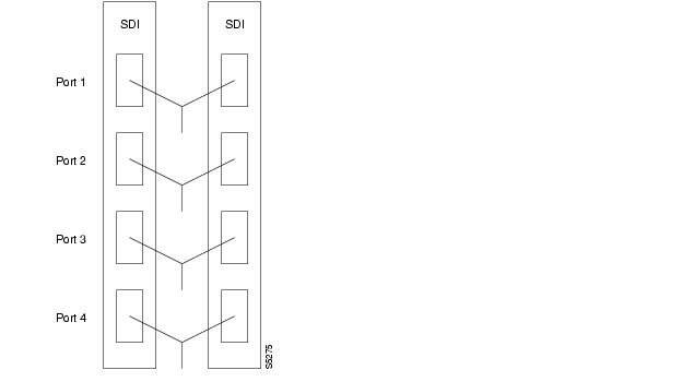
On multiport card sets, each primary port is connected by a Y-cable to a secondary (redundant) port. Port 1 of the primary card set must be paired to port 1 of the secondary card set, and so on. Figure 3-2 illustrates the cabling for a multiport card set.
Figure 3-2 Y-Cables on Multiple Ports
If the secondary card set becomes active, the primary card set goes into the standby state. For the primary card set to serve as a backup, it must be a complete set and not have failed status.
You can execute addyred even if the primary and secondary slots are empty. If cards reside in the primary and secondary slots, the system checks for card compatibility. Two types of incompatibility can occur: back card and jumper or cable. On SDI, FRI, and FTI cards, jumpers determine whether a port is configured as DCE or DTE. On LDI cards, either a DCE or DTE adapter cable connects to the LDI port, as applicable.
If incompatibilities exist, the message "Y-Cable Conflict" appears on screen. Specific conflicts are listed in reverse video in the Y-Cable Redundancy screen. See the dspyred description for details. Redundancy on V.35 versions of the SDI and FRI cards requires special redundant jumpers. Always use the applicable Y-Cable Redundancy kit for a card.
Card Redundancy for Virtual Trunking
Y-Cable redundancy is supported for both the UXM and BXM trunk cards at the edge of the ATM cloud.
Controlling External Devices
If your system is configured to control an external device, such as a multiplexer, you can establish a window session to it from the control terminal. While in a window session, any characters you type at the control terminal go to the external device for processing. Any characters generated by the external device appear on the control terminal screen.
The Window to External Device (window) command establishes a window session. You can use this command only if the external device connects to the local node. You can, however, enter the window command during a virtual terminal session so that you have a window session with any external device in the network. To start a window session, use the Virtual Terminal (vt) command to access the node cabled to the device, then invoke the window command. Before starting a window session, you must have configured the port and the port function with cnfterm and cnftermfunc. In addition, you must know whether the external window device is cabled to a node's Control Terminal (EIA/TIA-232) port or Aux Port (EIA/TIA-232) port. The format for the window command is:
window [a | c]
Enter an a if the external device is attached to the node's Aux Port or c if the device is attached to the node's Control Terminal port. The default for this parameter is Aux Port. To establish a window session with an external device attached to a node's Control Terminal port, enter:
window c
The system responds by redrawing the terminal screen. You can now enter commands and send data to the external device as if you were locally connected to its Control Terminal port. While in the window session, only commands used to control the external device are recognized. IGX/BPX commands are not recognized. You might notice a slight transfer delay in transmission, due to the IGX/BPX bundling of characters before transmitting them. Transfers are delayed until the transfer buffer is filled, or until the keyboard has been inactive for over 50 milliseconds.
To end a window session, enter an escape sequence. Escape sequences are one to eight characters in length and are configured with the Configure Terminal Port Function (cnftermfunc) command. For example, if you have specified "signoff" as the escape sequence in the Configure Terminal Port Function, enter the following to end the window session:
signoff
The default escape sequence is:
^^ (SHIFT 66)
If this escape sequence does not work and you do not know the configured escape sequence, leave the keyboard idle for four minutes. After four minutes, the system terminates the window session.
Command Sequences for Setting Up Nodes
The sequences in Figure 3-3, Figure 3-4, Figure 3-5, Figure 3-6, and Figure 3-7 show the commands you execute to do the following node-related tasks:
•
•
•
•
•
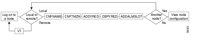
Figure 3-3 Setting Up Nodes
Figure 3-4 Viewing the Node Configuration
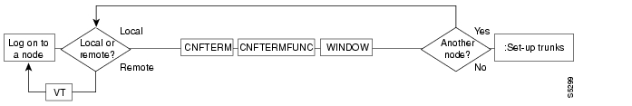
Figure 3-5 Configuring the Node Interface for a Local Control Terminal
Figure 3-6 Removing a Node From the Network
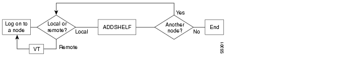
Figure 3-7 Add an Interface Shelf to the Network
Sending A-bit Notification on ILMI/LMI Using Configurable Timer
The Early Abit Notification on ILMI/LMI Using Configurable Timer feature provides a mechanism to send A-bit = 0 status change over the LMI interface or send ILMI traps over the ILMI interface after the connections are derouted a certain amount of time. You can configure this time period by setting some cnfnodeparm parameters. This configurable time approach provides you with the flexibility to synchronize the operation of the primary network and backup utilities, such as dialed backup over the ISDN or PSTN network. This feature is supported on both the BPX and IGX platforms.
Definitions of Terms Related to A-bit Notification using Configurable Timer Feature in Release 9.2
These brief definitions are relevant to the Early A-bit Notifications on ILMI/LMI Interface using Configurable Timer feature:
CPE
Customer premise equipment.
ILMI
Integrated Local Management Interface provides a means for configuration, status, and control information between two ATM entities.
LMI
Logical Management Interface provides a protocol to monitor the status of permanent virtual connections between two communication devices.
The Early Abit Notification on ILMI/LMI Using Configurable Timer feature allows A-bit notifications to be sent over the LMI/ILMI interface if a connection cannot be rerouted after a user-specified time. A-bit = 0 will not be sent if the connection is rerouted successfully during that time.
Purpose of Early Abit Notification on ILMI/LMI Using Configurable Timer Feature
The Early Abit Notification on ILMI/LMI Using Configurable Timer feature provides the user flexibility to configure the time when the node will start sending out A-bit = 0 after a connection becomes derouted. This allows the CPE to take appropriate actions such as initiating the dialed backup process if the deroute process has not finished during a certain period of time.
The Early Abit Notification on ILMI/LMI Using Configurable Timer feature is an enhancement to the Send A-bit on Deroute feature provided in Release 9.1.07 for the BPX. To minimize the risk in deploying this feature, and to continue to support the Send A-bit on Deroute feature, which was developed in Release 9.1.07 for BPX, the feature has the following guidelines:
•
•
•
•
Environment Required to use the A-bit Notification Using Configurable Timer Feature
The Early Abit Notification on ILMI/LMI Using Configurable Timer feature is supported on IGX and BPX switch software. No new hardware or firmware is required on line cards or feeder trunk cards.
Configuration of A-bit Notification Feature
You can enable the Early Abit Notification on ILMI/LMI Using Configurable Timer feature on both IGX and BPX by using cnfnodeparm command parameters Send A-bit Early, A-bit Timer Multipler M, and A-bit Timer Granularity N.
Compatibility
A Release 9.2 IGX or BPX node using this feature is compatible with Release 8.4 and Release 8.5 nodes or Release 9.1 IGX and BPX nodes so that all existing connection related functions will continue to work. However, the timing in sending out the A-bit notifications at both ends of connections may behave differently, depending on how this feature is configured.
Overview of A-bit Notification Feature
The time to reroute connections varies depending on different parameters, such as the number of connections to reroute, reroute bundle size, and so on. It is important to notify the CPE if a connection is derouted and fails to transport user data after a specified time interval. However, it is desirable not to send out A-bit = 0 and then A-bit = 1 when a connection is derouted and rerouted quickly, because such notifications may trigger the CPE backup facilities, which is a costly process and may cause fluctuations in an otherwise stable system. The configurable time interval is a direct solution to these problems.
Function of the Early Abit Notification on ILMI/LMI Using Configurable Timer Feature
The Early Abit Notification on ILMI/LMI Using Configurable Timer feature allows you to specify the time interval after which to start sending out A-bit = 0 if a connection fails to reroute and is in the derouted state too long. To avoid having an adverse performance impact on the system, no precise timer is kept for each connection. Instead, all connections derouted during a certain time period go to the same bucket.
This time period is referred to as N, which defines the granularity of the timers, and is specified by the value of the cnfnodeparm A-bit Timer Granularity N parameter. Another parameter is the time to wait before A-bit = 0 is sent out if the connection is in a derouted state. This parameter is called X. A connection that is derouted at a period of time between 0 and N will send out A-bit = 0 at a time between X and X + N, if the connection continues to be in a derouted state. In cases where there are many A-bit status changes to report to CPE, the last A-bit updates may be delayed much longer because A-bit updates process about 47 connections per second.
To make a compromise between performance and the granularity of timers, N can be configured to be from 3 to 255 seconds; the bigger the value of N, the better the system performance will be. The other parameter, X, is set to be M * N, where M can be configured to be from 0 to 100. The default value for N is 3 sec. Default value for M (A-bit Timer Multiplier M parameter) is 0, meaning A-bit = 0 is sent out on deroute.
It is recommended that X (value of A-bit Timer Multiplier M * the value of the A-bit Timer Granularity N) be set such that when a trunk fails, the connections are given sufficient time to reroute successfully, avoiding the need to send out A-bit = 0.
The change in the A-bit behavior is completely local to the node and is applicable to the master and slave ends of connections when the connections are derouted. When only one of the nodes connected by a connection has this feature turned on, the timing in sending the A-bit notification at one end of the connection may be drastically different from the other end. Therefore it is recommended that the Early Abit Notification on ILMI/LMI Using Configurable Timer feature be configured the same on all nodes. Also, because timers on nodes are not in sync, there is a slight time difference (3 seconds maximum) in sending A-bit from the two ends of a connection, even if the cnfnodeparm parameter settings on the nodes are the same.
Note
If the value of X (value of A-bit Timer Multiplier M * value of A-bit Timer Granularity N) is set to be smaller than the normal time to reroute connections when a trunk fails, the time it takes to finish rerouting them may take longer. This can happen for line cards and feeder trunks, which have the LMI/ILMI protocol running on those cards, such as BXM on BPX and Frame Relay cards on IGX. Note that it takes time for those cards to process the A-bit status information for each connection coming from the controller card.
Caution
There is no impact on control processor switchover or trunk card redundancy switchover because connections are not rerouted.
Using the Early Abit Notification on ILMI/LMI Using Configurable Timer Feature
In releases previous to Release 9.1.07, when connections are derouted, the CPE does not receive A-bit notifications. In Release 9.1.07 on BPX, the Send A-bit on Deroute feature was developed, which allowed the A-bit = 0 to be sent immediately when a connection is derouted. (This was specified by the cnfnodeparm parameter Send A-bit immediately parameter.) To further enhance the Send A-bit on Deroute feature in Release 9.1.07, the Early Abit Notification on ILMI/LMI Using Configurable Timer feature has been implemented in Release 9.2 to allow the network administrator to configure the node as to when A-bit = 0 is sent out if a connection is derouted and not rerouted quickly. This feature allows you to specify when A-bit notifications will be sent at Frame Relay and ATM ports, and at feeder trunks in a tiered network architecture that supports the ILMI/LMI interface. In a tiered network, the A-bit information is used by the feeder nodes such as MGX 8220 (AXIS), which then relays the A-bit information to the CPE.
The status update messages are throttled at the rate of one message per second. Each message can be used to specify the conditioning information on a maximum of 47 connections. It may take on the order of minutes for the ILMI/LMI manager to process the A-bit status when there is a large number of connections.
Performance of Sending A-bit Notification Using Configurable Timer Feature
There are two factors in performance: system performance and reroute time. System performance is affected by the value of the time interval. In a network where connections are normally derouted and rerouted quickly before the bucket timer expires, the performance impact is very small. Only when the timer expires, then looping through all LCONs and sending update messages will take up some CPU time, which is estimated to be smaller than 1 percent.
Reroute time is not affected if LMI/ILMI is running on the controller card. When the protocol is implemented on the line cards and feeder trunk cards, some additional A-bit status communication between them and controller card may delay the reroute process.
Specifically, on the BPX, if the BXM runs LMI/ILMI, the BCC has to send A-bit updates to the card. These messages will be throttled. When this happens, the estimated time to reroute all 12K connections increases no more than 5 percent.
For the IGX, enabling the Sending A-bit Notification using Configurable Timer feature may impact performance if many connections end at Frame Relay cards. This is due to the restricted format of interface between NPM and Frame Relay cards.
Reliability, Availability, and Serviceability (RAS)
Together with the CPE equipment that has dialed backup capability, this feature increases the availability of the services between the CPEs.
Interoperability with Previous Release of Switch Software
This feature is blocked until all nodes are running Release 9.2. A Release 9.2 node with or without this feature being turned on can interwork with other 8.4 or 8.5 nodes or Release 9.1 nodes with all existing connection management functionality.
Summary of Commands
Table 3-1 shows the command name and starting page for the description of each node command.
addalmslot
Enables the MAJOR and MINOR alarm indicators on an Alarm Relay Card (ARC) or Alarm Relay Module (ARM) front card. It also configures the slot to provide external alarms from the Alarm Relay Interface (ARI) back card. You should use this command at each node equipped to provide external alarm indications to the customer alarm reporting system. The slot specified for the ARC or ARM may be any shelf slot, but is usually the slot farthest to the right.
Upon executing the command, the system places the alarm card set in the active state and displays the current alarm status.
Full Name
Add alarm slot
Syntax
addalmslot <slot number>
Related Commands
delalmslot, dspalms
Attributes
Example 1
addalmslot 16
Description
Enable alarm reporting from slot 16 in a node. (The system then displays alarm status.)
System Response
beta TRM YourID:1 IGX 8430 9.2 Aug. 3 1998 14:27 MSTAlarm summary (Configured alarm slots: 16)Connections Failed: NoneGroups Failed: NonePLN Alarms: 1 MajorCLN Alarms: NoneCards Failed: 1Missing Cards: NoneRemote Node Alarms: 1 MajorRemote Domain Alarms: NoneLast Command: addalmslot 16Next Command:
Table 3-2 addalmslot-Parameters
slot number
Specifies the slot number of the alarm card set.
addcdred
The addcdred is an alias for the addyred command (thus has identical functionality) which lets you enable card and line redundancy for the cards on the IGX and BPX. It lets you add card and line redundancy for APS 1+1 across two BXM OC-3 and OC-12 cards. You also use it before enabling APS 1:1 line redundancy. It works similarly to the addyred command.
Use the addcdred command to specify the slots of the primary and secondary (standby) cards that form the redundant pair.
When configuring APS 1+1 card and line redundancy, you must execute the addcdred command before using addapsln. Refer to the BPX 8600 Installation and Configuration Guide for more information on setting up APS 1+1 card and line redundancy.
Redundant card sets must have the following characteristics:
•
•
•
•
•
In both the single and multiport card sets, if the secondary card set becomes active, the primary card set serves as its backup (assuming the primary card set is complete and not failed). You cannot use the addcdred command on empty card slots. If one or both of the card slots is empty, and you use the addcdred command, the command will fail.
If cards reside in the primary and secondary slots, the system checks for card compatibility. The following types of incompatibility can occur: back card and jumper or cable inconsistencies. Also, the addcdred command can fail because of firmware capabilities conflicts. For example, if one of the cards supports virtual trunking, and the other doesn't support virtual trunking, the addcdred command might fail. Refer to the Cisco BPX 8600 Series Installation and Configuration manual for more information on configuring SONET APS 1+1 card and line redundancy for BXM OC-3 and OC-12 cards.
APS 1+1 Environment (Using Redundant Backcards, with Front Card Redundancy)
The same numbered ports on adjacent BXM cards are used. A hardware, firmware, and software upgrade is required. (Firmware that supports APS 1+1 setup, and switch software Release 9.2 is required.)
The APS 1+1 feature requires two BXM front cards, an APS redundant frame assembly, and two redundant type BXM backcards. The two redundant BXM backcards are plugged into the APS redundant frame assembly. (Refer to the SONET APS Configuration chapter in the Cisco BPX 8600 Series Installation and Configuration guide for more information on APS hardware configuration.) The types of redundant back card and backplane sets required are:
•
•
•
•
•
•
Each of the listed model numbers includes two single back cards and one mini-backplane (providing cross-=coupling of two back cards).
The single back cards and mini-backplane can be ordered as spares. Their model numbers are:
•
•
•
•
•
•
•
Note
If incompatibilities exist, the message "Y-Cable Conflict" appears on the screen. Specific conflicts are listed in reverse video on the dspcdred display. See the dspcdred description for more information.
Note
In this release, to ensure that only cards with the Idle Code Suppression feature enabled on them are allowed to be a Y-redundancy pair, addcdred blocks cards that have different idle code suppression capability.
Full Name
Add card redundancy for SONET Automatic Protection Switching (APS) across two OC-3 or OC-12 cards.
Syntax
addcdred <primary slot> <secondary slot>
Related Commands
delcdred, dspcdred, prtcdred, switchcdred
Attributes
Example 1
addcdred 2 3
Description
Add redundant line on port 1 for BXM OC-3 card and APS backcards in slots 2 and 3 of the BPX.
System Response
beta TRM YourID:1 BPX 8620 9.2 Aug. 15 1997 14:27 MSTSlot Other Front Back Channel ConfigurationSlot Type Slot Card Card 1 2 3 4 5 6 7 82 Pri 3 BXM LM-BXM3 Sec 2 BXM LM-BXMLast Command: addcdred 2 3Next Command:
Table 3-3 addcdred-Parameters
primary slot
Specifies the slot number of the primary card set.
secondary slot
Specifies the slot number of the secondary card set.
addshelf
Adds an ATM link between an IGX/BPX core switch shelf and an interface shelf such as an MGX 8220, MGX 8850, IGX shelf, or SES (Service Expansion Shelf) in a tiered network; or an ATM link between a BXM card on a BPX node and a Label Switch Controller (LSC) such as a series 7200 or 7500 router; or an ATM link between a BXM card on a BPX node. (An MPLS controller is considered an interface shelf from the BPX's perspective.) The routing hub can be either a BPX or an IGX.
The interface shelf can be one of the following:
•
•
•
•
•
•
The signaling protocol that applies to the trunk on an interface shelf is Annex G. (Annex G is a bidirectional protocol defined in Recommendation Q.2931, used to monitor the status of connections across an UNI interface. The Annex G protocol is used in this release to pass connection status information between an IGX/BPX core switch shelf and an attached feeder.)
Note
Each IGX/AF, MGX 8220, MGX 8850, or SES shelf has one trunk that connects to the BPX or IGX node serving as an access hub. A BPX routing hub can support up to 16 T3 trunks to the interface shelves, which can be IGX/AF, MGX 8220, or MGX 8850 interface shelves. An IGX hub can support up to four trunks to the interface shelves, which can be IGX/AF or SES (Service Expansion Shelf) shelves.
Before it can carry traffic, you must "up" the trunk on an interface shelf (using uptrk on both the interface shelf and the IGX/BPX core switch shelf) and "add" it to the network (using addshelf). Also, a trunk must be free of major alarms before you can add it with the addshelf command.
In this release, the commands addshelf and addctrlr are used to add an MPLS/PNNI controller to the BPX. The command addshelf with option "v" is used to add a VSI shelf. This is used mainly for MPLS controllers. The command addctrlr is used to add a controller to a shelf that has LMI capabilities.
In this release, you can use an IGX as a feeder node to connect via a UXM IMA trunk to an IGX or BPX router node using IMATM. You use addshelf with the "I" option at the IGX node to add the feeder trunk connecting it to an IGX feeder node.
Full Name
Add an interface shelf (feeder) or a controller to a routing node or hub
Syntax
Interface shelf:
addshelf <slot.port> <shelf-type> [vpi] [vci]
addshelf <slot>.<primary link> <shelf type>Tag switch controller:
addshelf <slot.port> <device-type> <control partition> <control ID>
VSI controller:
addshelf <trunk slot.port> v <ctrlr id> <part id> <control vpi> <control vci start> <redundant ctrlr warning>
Note
Related Commands
delshelf, dspnode, dsptrks
Attributes
Example 1
Interface shelf: addshelf 11.1 a 21 200
Label switch controller: addshelf 4.1 vsi 1 1
Description
Interface shelf:
Add trunk 11.1 as an MGX 8220 interface shelf. After you add the shelf, the screen displays a confirmation message and the name of the shelf.
MPLS controller:
Add trunk 4.1 as an MPLS Controller interface shelf. After you add the MPLS controller, the screen displays a confirmation message and the name of the shelf.
Description for Interface Shelves
An interface shelf can be one of the following:
•
•
•
•
Example for Interface Shelves
Add an MGX 8220 at trunk 11.1 After you add the shelf, the screen displays a confirmation message and the name of the shelf. Add the MGX 8220 (may be referred to on screen as AXIS) as follows:
addshelf 11.1 a
The sample display shows a partially executed command prompting you for the interface shelf type:
System Response
nmsbpx23 TN SuperUser BPX 620 9.2 Apr. 4 1998 13:28 PSTBPX Interface Shelf InformationTrunk Name Type Alarm1.3 AXIS240 AXIS OK11.2 A242 AXIS OKThis Command: addshelf 11.1Enter Interface Shelf Type: I (IGX/AF), A (AXIS), P (APS), V (VSI), X (AAL5)Next Command:Example for Adding an MGX 8850 (AAL5) Interface Shelf to a BPX Routing Node
Add an MGX 8850 at trunk 4.1. After you add the MGX 8850 interface shelf, the screen displays a confirmation message and the name of the shelf. Add the MGX 8850 (may be referred to on-screen as AAL5) as follows:
addshelf 4.1 x
The sample display initially shows the output of a dsptrks command, then shows how an MGX 8850 was added on trunk 4.1 as an AAL5 type of interface shelf. (AAL5 is the ATM Adaptive Layer 5 protocol, which is an ATM standard interface that is used by the routing node or routing hub to communicate to the MGX 8850 and Service Expansion Shelf feeders.) Adding an MGX 8850 interface shelf or a Service Expansion Shelf is similar to adding an MPLS controller or a PNNI controller.
In releases previous to Release 9.2.10, for BTM E1/T3 feeder interface types, addshelf does not prompt you for the "Interface Shelf Type." In this release, addshelf will prompt you for the "Interface Shelf Type." (This is needed to distinguish which signalling protocol is used.) Because MGX 8220, MGX 8850 and SES use the same LMI signalling protocol, you will be prompted for the "Interface Shelf Type (A) AAL5."
System Response
sw288 TN SuperUser BPX 8620 9.2.j2 Dec. 10 1998 15:38 PSTTRK Type Current Line Alarm Status Other End4.1 OC-12 Clear - OK -11.2 T3 Clear - OK redhook/1411.3 T3 Clear - OK sw113/16This Command: addshelf 4.1Enter Interface Shelf Type: I (IGX), A (AXIS), P (APS), V (VSI), X (AAL5)BPX Interface Shelf InformationTrunk Name Type Part Id Ctrl Id Alarm4.1 SIMFDR0 AAL5 - - OKThis Command: addshelf 4.1 xEnter Interface Shelf Type: A (AXIS), P (APS), V (VSI), X (AAL5)Shelf has been addedNext Command:Example for Adding a Service Expansion Shelf (SES) to an IGX 8400
Add an SES interface shelf to an IGX 8400 (using a UXM or UXM-E interface). After you add the SES interface shelf, the screen displays a confirmation message and the name of the shelf. Add the SES (may be referred to on-screen as AAL5) as follows:
addshelf 6.1 X
Enter Interface Shelf Type: X (AAL5)
Note
System Response
sw288 TN SuperUser IGX 8420 9.2.2I Dec. 10 1998 15:38 PSTTRK Type Type Alarm9.1 ases1 AAL5 MINThis Command: addshelf 4.1Enter Interface Shelf Type: I (IGX), A (AXIS), P (APS), V (VSI), X (AAL5)IGX Interface Shelf InformationTrunk Name Type Alarm9.1 ses_fdr AAL5 MINThis Command: addshelf 4.1 xEnter Interface Shelf Type: A (AXIS), P (APS), V (VSI), X (AAL5)Shelf has been addedNext Command:The sample display shows that an SES was added on trunk 9.1 as an AAL5 type of interface shelf. (AAL5 is the ATM Adaptive Layer 5 protocol, which is an ATM standard interface that is used by the routing node or routing hub to communicate with the SES shelves.) Adding an IGX interface shelf is similar to adding an MPLS (Multiprotocol Label Switching) controller as an interface shelf.
The addshelf command will prompt for "Interface Shelf Type." Because the MGX 8220, MGX 8850, and the SES (Service Expansion Shelf) use the same Annex G LMI signalling protocol to communicate with an IGX routing hub, they all use the same interface shelf type of AAL5 (designated by the addshelf "X" option).
Types of Interface Shelves Supported in Release 9.2
Previous to Release 9.2, WAN switching software supported the ability to configure an IGX 8400 as an interface shelf to the IGX 8400 hub over a BTM E1 and T3 interface. Also, the MGX 8220 (formerly called "AXIS") is supported as an interface shelf to the BPX. Release 9.1 introduced the ability for the MGX 8850 to serve as an interface shelf to a BPX routing hub. Release 9.2 introduced the ability for an SES (Service Expansion Shelf) to serve as an interface shelf to an IGX 8400 routing hub.
UXM Feeder Support in Release 9.2
In Release 9.2.20, the following are supported:
•
•
•
Not Supported in Release 9.2
An MGX 8220 or an MGX 8850 can connect as interface shelves to a BPX routing node. An IGX interface shelf can connect to an IGX 8400 routing node over a UXM/UXM-E interface. Similarly, in Release 9.2.10, an SES can connect to an IGX routing hub over a UXM/UXM-E interface. However, you cannot do the following:
•
•
•
•
Signalling Channel Used by MGX 8850 and SES Interface Shelves Connecting to Routing Hubs
Previous to Release 9.2, the IGX 8400 interface shelf communicated with the IGX 8400 routing hub using a BTM E1 interface over the Annex G LMI with STI format. In Release 9.2, the SES interface shelf with a UXM/UXM-E interface communicates with the routing hub over an Annex G LMI interface by using AAL5 format.
Note
An SES feeder uses the Annex G protocol to pass connection status information between itself and an IGX 8400 routing hub. Similarly, an MGX 8850 feeder uses the Annex G signalling channel to pass connection status information between itself and a BPX routing hub.
Previous to Release 9.2, IP relay was supported by encapsulating the IP data in a network message when interfacing with an IGX 8400 interface shelf. In this release, the SES interface shelf communicates with an IGX routing hub through ATM cells. Thus, IP data destined for an IGX 8400 is encapsulated in an AAL5 ATM cell format.
addshelf Error Messages
Some of the possible error messages for the addshelf command:
–
–
–
–
–
–
–
–
–
–
–
–
–
–
–
–
System Response
pswbpx3 TN SuperUser BPX 8600 9.1 June 6 1998 13:28 PSTBPX Interface Shelf InformationTrunk Name Type Part Id Ctrl Id Alarm4.8 SIMFDR0 AAL5 - - OKThis Command: addshelf 4.8 xEnter Interface Shelf Type: I (IGX/AF), A (AXIS), P (APS), V (VSI), X (AAL5)Next Command:Description for Label Switching
For label switching, before it can carry traffic, you need to "up" the link to a tag switch controller (using either uptrk or upport) at the BPX node. You can then "add" the link to the network (using addshelf). Also, the link must be free of major alarms before you can add it with the addshelf command.
Note
Example for Multiprotocol Label Switching
Add an LSC (Label Switch Controller) link to a BPX node by entering the addshelf command at the desired BXM port as follows:
addshelf 4.1 vsi 1 1
System Response
nmsbpx23 TN SuperUser BPX 15 9.2 Apr. 4 1998 13:28 PSTBPX Interface Shelf InformationTrunk Name Type Alarm5.1 j6c AXIS MIN5.3 j5c IGX/AF MIN4.1 VSI VSI OKThis Command: addshelf 4.1 v 1 1Next Command:Example for Adding a Redundant VSI Controller
addshelf 11.1 vsi 1 2
Description
Add a redundant (more than one) VSI controller (as an interface shelf to a BPX node), on slot 11 on port 1, with a control partition of 1 and control ID of 2.
System Response
night TN StrataCom BPX 8600 9.2.00 Apr. 11 1998 14:31 GMTBPX Interface Shelf InformationTrunk Name Type Part Id Ctrl Id Alarm1.1 sww222 IGX/AF - - UNRCH10.3 VSI VSI 1 1 OKWarning partition already in use do you want to add redundant controller?Last Command: addshelf 11.1 vsi 1 2Example 4
addshelf 4.1 vsi 1 1
Description
Add a VSI controller to port 4.1, controlling partition 1
Note
System Response
n4 TN SuperUser BPX 8620 9.2 Apr. 4 1998 16:42 PSTBPX Interface Shelf InformationTrunk Name Type Alarm3.1 j6c AXIS MIN5.3 j5c IGX/AF MIN4.1 VSI VSI OKLast Command: addshelf 4.1 vsi 1 1Next Command:addyred
The addyred command performs the same function as the addcdred command. It enables card redundancy for cards on the IGX and BPX. Use the addyred command to specify the slots of the primary and secondary (standby) cards that form the redundant pair. Refer to the " Specifying Card Redundancy" section at the beginning of this chapter for a list of supported card sets.
Redundant card sets must have the following characteristics:
•
•
•
•
•
If cards reside in the primary and secondary slots, the system checks for card compatibility. Two types of incompatibility can occur: back card and jumper or cable inconsistencies. (On SDI, FRI, and FTI cards, jumpers determine whether a port is configured as DCE or DTE. On LDI cards, either a DCE or DTE adapter cable connects to the LDI port. For descriptions of the jumper positions and cabling, see the Cisco IGX 8400 Series Installation and Configuration manual.)
Note that the addyred command prevents invalid configurations when you try to configure the SONET APS feature. When SONET Automatic Protection Switching (APS) is configured, you will not be able to use the addyred or delyred commands on a card configured for APS 1:1 architecture. That is, you will not be able to execute the addyred command, then configure the APS 1:1 architecture. Similarly, you will not be able to configure APS 1:1, then execute the addyred command. You will be blocked from executing these commands at the command line interface.
If incompatibilities exist, the message "Y-Cable Conflict" appears on the screen. Specific conflicts are listed in reverse video in the dspyred display. See the dspyred description for more information.
To ensure that only cards with the Idle Code Suppression feature enabled on them are allowed to be a Y-redundancy pair, addyred blocks cards that have different idle code suppression capability.
The addyred commands (addyred, delyred, dspyred, prtyred, switchyred) will perform feature mismatch checking on both the primary and secondary cards. For information on feature mismatch checking, refer to the BPX 8600 Series Installation and Configuration.
Mismatch Checking Performed by addyred/delyred
During addyred's mismatch checking, the following verifications are done:
•
•
•
Full Name
Add Y-cable redundancy
Syntax
addyred <primary slot> <secondary slot>
Related Commands
delyred, dspyred, prtyred
Attributes
Example 1
addyred 2 3
Description
Add Y-cable redundancy to the BXM card sets in slots 2 and 3.
System Response
beta TRM YourID:1 BPX 8620 9.2 Aug. 15 1998 14:27 MSTSlot Other Front Back Channel ConfigurationSlot Type Slot Card Card 1 2 3 4 5 6 7 82 Pri 3 BXM LM-BXM3 Sec 2 BXM LM-BXMLast Command: addyred 2 3Next Command:
Table 3-6 addyred-Parameters
primary slot
Specifies the slot number of the primary card set.
secondary slot
Specifies the slot number of the secondary card set.
cnfasm
Lets you set various configurable parameters associated with the BPX Alarm and Status Monitor card in slot 15. Because this card always resides in slot 15, entering the slot number is unnecessary. In Release 9.2 and above, robust alarms are generated for the following alarm conditions:
•
•
•
•
•
•
These alarm conditions above appear in the maintenance log or in the node command line interface commands (dspasm), and are not also reported as SNMP trap to the customer NMS. (Such traps are generated by the Cisco WAN Manager RTM proxy upon receiving Robust Alarms from a switch.)
In Release 9.2 and above, robust alarms are generated by the BPX when power and temperature alarm conditions are detected by the ASM card. The ASM card monitors and reports events involving:
•
•
•
•
You configure and control the reporting of these events through the cnfasm command, where you can enable or disable each alarm. For power supply failure/removal events, you can also specify the alarm class (that is, Major vs. Minor).
A robust alarm is generated by the following:
•
•
–
–
–
–
–
Full Name
Configure ASM (Alarm and Status Monitor) card
Syntax
cnfasm
Related Commands
dspasm
Attributes
Example 1
cnfasm
Description
Configure parameters for the ASM card
System Response
D1.jea TRM SuperUser BPX 8600 9.2 Aug. 30 1998 12:25 GMT[1] Cabinet temp threshold: 50 C [4] Polling interval (msec): 10000[2] Power A deviation: 6 V [5] Fan threshold (RPM): 2000[3] Power B deviation: 6 VALM ALM[6] ACO button - [14] BPX card slot -[7] History button - [15] PSU A failure Y[8] Cabinet temp Y [16] PSU A removed Y[9] Power A volt Y [17] PSU B failure Y[10] Power B volt Y [18] PSU B removed Y[11] Fan 1 RPM Y[12] Fan 2 RPM Y[13] Fan 3 RPM YThis Command: cnfasmWhich parameter do you wish to change:cnfdate
Sets the date and time for the entire network. The node broadcasts the specified date and time to every node in the network. The time displayed at each node is consistent with the time zone where the node resides. (See the cnftmzn description.) For the first-time configuration of the date and time in a network, cnfdate requires all the parameters except for second. The default for second is 0. If a date and time already exist in the network, the defaults are the existing values at the moment you enter the cnfdate command. Note that changes to date and time alter the time-stamps on WAN Manager statistics.
Full Name
Configure data and time
Syntax
cnfdate <year> <month> <day> <hour> <minute> [second]
Related Commands
cnftime, cnftmzn
Attributes
Example 1
cnfdate 1997 12 16 13 54 11
Description
Set the time to 1:54:11 PM, December 16, 1997. The system prompts:
"Warning: Changing time of day affects StrataView statistics time-stamps.Continue?"
Enter "y" to continue or "n" to abort." Upon a "y" response, the system further prompts with: "Hit RETURN to change clock, DEL to abort."System Response
alpha TRM YourID:1 IGX 8420 9.2 Dec. 16 1998 13:54 PSTYourID 1Sarah 5Last Command: cnfdate 1997 12 16 13 54 11Warning: Changing time of day affects StrataView statistics timestampsContinue?
Table 3-8 cnfdate-Optional Parameters
second
Specifies the seconds. The range is 0-59. The default is 0.
cnffunc
Enables or disables a specified node function. Each function has an index number. By entering the command, the index parameter, and the letter "e" or "d," the function is either enabled or disabled.
Upgrading from Release 9.1 to Release 9.2 when IMA Trunks Exist
When IMA trunks exist in a Release 9.1 network, and you are upgrading from Release 9.1 to 9.2, ensure that the following steps have been performed:
•
•
You are now ready to upgrade the switch software from Release 9.1 to 9.2.
Full Name
Configure system functions
Syntax
cnffunc <function_index> <e/d>
Related Commands
none
Attributes
Example 1
cnffunc 7 e
Description
Enables automatic card testing after a card failure has been detected.
System Response
sw199 TN StrataCom IGX 8420 9.2 Apr. 9 1998 18:14 GMTIndex Status Function1 Enabled Automatic CLN/PLN Loopback Test on Local/Remote Alarms2 Enabled FDP Loopback button3 Enabled User Command Logging4 Enabled Automatic Card Reset on Hardware Error5 Enabled TXR Model D Download6 Enabled Card Error Record Wraparound7 Disabled Card Test After Failure8 Disabled Download From Remote StrataView9 Disabled Logging of conn events in local event log10 Disabled Logging of conn events in SV+ event log11 Disabled Logging SVC Connection Events12 Disabled Force Download From a Specific IP address13 Disabled CDP WinkStart SignallingThis Command: cnffuncContinue? yIndex Status Function14 Enabled Logging of Bus Diagnostic Events in local event logThis Command: cnffuncEnter index:
cnfname
Specifies the name by which a node is known within the network. It may be changed at any time. The new node name is automatically distributed to the other nodes in the network. Node names are case sensitive. For example, an upper-case "A" is not considered to be the same as a lower-case "a". Duplicate names are not allowed in the same network. Node names may be configured from within a job sequence. If the node name is changed and the corresponding name in the job is not changed, the job will not function properly. In the following situations, the cnfname command cannot be executed:
•
•
•
•
Full Name
Configure node name
Syntax
cnfname <nodename>
Related Commands
cnfterm, cnfprt, and window
Attributes
Example 1
cnfname alpha
Description
The name changes to "alpha." The network topology screen displays indicating the new name. See the dspnw description for more information on the network topology screen.
System Response
alpha TRM YourID:1 IGX 8410 9.2 Aug. 15 1998 12:02 PSTNodeName Alarm Packet Line Packet Line Packet Linealpha 10- 7/beta 14- 13/betabeta MAJOR 7- 10/alpha 9- 10/gamma 13- 14/alpha15- 15/gamma 20- 11/gammagamma MAJOR 10- 9/beta 11- 20/beta 15- 15/betaLast Command: cnfname alphaNext Command:cnfprt
Configures the printing function. To obtain local or remote printing at a node, a printer must connect to the AUX PORT. Also, the configuration must include the correct baud rate and printer type for the port. Use the cnfterm and cnftermfunc commands to do this.
The cnfprt and cnftermfunc commands interact. If the auxiliary port on the node is configured for either an External Device Window or the Network Management Log, a "local" printing configuration automatically changes to "no printing." Printing is not possible because the auxiliary port is being used for another purpose.
Establishing a virtual terminal connection with a node does not affect the printing location established for the node that initiates the virtual terminal connection. For example, if node alpha is configured so that all alpha information goes to a printer at node beta and if alpha establishes a virtual terminal connection with node gamma, the results of print commands entered on the alpha keyboard still print at beta. Furthermore, this occurs regardless of the printing location configured for node gamma.
Full Name
Configure printing functions
Syntax
cnfprt <mode> <remote node name>
Related Commands
cnfterm, dsptermfunc
Attributes
Example 1
cnfprt
Description
Change the configured printing.
System Response
alpha TRM YourID:1 IGX 8410 9.2 Aug. 15 1998 13:17 PSTPrinting ModeRemote Printing at betaLocal PrintingNo PrintingThis Command: cnfprtSelect Local (l), Remote (r), or None (n):
cnfterm
Configures data transmission parameters for the control and auxiliary ports. The IGX and BPX nodes support two EIA/TIA-232 serial ports on the upper bus expansion card. The top port is called the Control Terminal port. The lower port is called the Auxiliary Port (AUX). Parameters can vary with the equipment connected to the port. The control port may connect to a control terminal, a direct-dial modem, or an external EIA/TIA-232 device. The auxiliary port may connect to either a printer or an external EIA/TIA-232 device. After you have set the data transmission parameters for a port, use the superuser command cnftermfunc to specify the equipment attached to the port. The configuration parameters must match the equipment physically attached to the port.
Full Name
Configure terminal port
Syntax
cnfterm <a/c> <baud> <parity> <num_data_bits> <num_stop_bits>
Related Commands
cnfterm, cnfprt, window
Attributes
Example 1
cnfterm
Description
Configure an auxiliary control port
System Response
alpha TRM YourID:1 IGX 8430 9.2 Aug. 15 1998 11:58 PSTControl port Auxiliary portBaud Rate: 1200 Baud Rate: 9600Parity: None Parity: NoneNumber of Data Bits: 8 Number of Data Bits: 8Number of Stop Bits: 1 Number of Stop Bits: 1Output flow control: XON/XOFF Output flow control: XON/XOFFInput flow control: XON/XOFF Input flow control: XON/XOFFUse DTR signal: Yes DTR signal: YesThis Command: cnftermSelect Control port (c) or Auxiliary port (a):
cnftime
Sets the time for the entire network. The time is broadcast to all nodes in the network. The time displayed at each node is adjusted for the node's time zone. (See the cnftmzn command for more information.) This command can only be executed if the date for the network has already been configured using the cnfdate command. If hour, minute, or second is not entered, the current value is kept.
Full Name
Configure time
Syntax
cnftime <hour> <minute> <second>
Related Commands
cnfdate, cnftmz
Attributes
Example 1
cnftime 19 31 00
Description
Configure time to 7:31 in the evening. The system displays two warning prompts before it changes the time.
pubsigx1 TN SuperUser IGX 8430 9.2 Sep. 5 1998 19:31 GMTThis Command: cnftime 19 31 00Warning: Changing time of day affects StrataView statistics timestampsHit RETURN to change clock, DEL to abort
cnftmzn
Configures the time zone for the node. Configuring the time zone for a node ensures that the node's time is correct for the local area regardless of the node at which the network date and time are set. Once configured, the time zone for the node is saved in battery-backed memory. After a power failure, a node's date and time are restored if at least one other node in the network has the current time and date.
Full Name
Configure time zone
Syntax
cnftmzn <timezone | g+/- hours>
Related Commands
cnfdate
Attributes
Example
cnftmzn pst
Description
Configures the time zone to Pacific Standard Time.
System Response
alpha TRM YourID:1 IGX 8420 9.2 Aug. 15 1998 13:19 PSTLast Command: cnftmzn pstNext Command:
delalmslot
Disables the ARC (IPX) or ARM (IGX) alarm indicators and ARI external alarms. See the addalmslot description for more information on ARC/ARM alarm relays and adding alarm slots.
Upon receiving the command, the system places the alarm card set in the standby state and displays the current alarm status.
Full Name
Delete an alarm slot
Syntax
delalm <slot number>
Related Commands
addalmslot, dspalms
Attributes
Example 1
delalmslot 11
Description
Disable the alarm indicators on the ARM card set in slot 11. (The system subsequently displays alarm status.)
System Response
pubsigx1 TN SuperUser IGX 8430 9.2 July 16 1998 02:09 GMTAlarm summary (Configured alarm slots: None)Connections Failed: NoneGroups Failed: NoneTRK Alarms: NoneLine Alarms: NoneCards Failed: NoneMissing Cards: NoneRemote Node Alarms: 1 MinorRemote Domain Alarms: NoneRouting Network Alarms: NoneCabinet Fan(s) FailedFastPAD Node Alarms: NoneLast Command: delalmslot 11Next Command:
Table 3-14 delamslot-Parameters
slot number
Specifies the slot number of the alarm card set to activate.
delcdred
The delcdred command disables card redundancy for the card set in the specified primary slot number. If the secondary card slot is being used as the active slot at the time you use the delcdred command, the system attempts to switch back to the primary slot. The substitution takes place only if the primary slot has a complete set of cards and the cards are in a Standby or a Standby-F state (not if they are Failed). See the dspcds description for information on card states.
When you issue the delcdred command, it always completes. If the primary card is incomplete, control will still be given to the primary card.
Because YRED (Y redundancy) could be considered a misnomer for the SONET APS two-slot case, the following new commands are new in Release 9.2 to support card redundancy:
•
•
•
•
•
See the addcdred and dspcdred commands for more information on card and line redundancy for SONET APS (Automatic Protection Switching) 1+1.
Full Name
Delete redundant card
Syntax
delcdred <primary slot>
Related Commands
addcdred, dspcdred, switchcdred
Attributes
Example
delcdred 2
Description
Delete card redundancy for slot 2.
delshelf
Deletes an interface shelf from a tiered network. The identifier for an interface shelf is either the trunk number or the name of the shelf. Normally, you do not execute delshelf only at the BPX core switch shelf, but on the IGX/AF itself. The delshelf command has the single function of letting you turn off LMI if the trunk is not allowing communication. In contrast to the deltrk command, you can execute delshelf at any time if no connections terminate at the trunk.
In Release 9.2 and above, when you use delshelf to remove an MGX 8850 interface shelf trunk from a BPX routing hub, or an SES interface shelf (or feeder) trunk from an IGX 8400 routing node, the Annex G signalling channel and IP relay programming for the MGX 8850 or SES interface shelf is removed.
Full Name
Delete an interface shelf
Syntax
delshelf <trunk> | <shelf-name>
Related Commands
addshelf, dspnode
Attributes
Example 1
delshelf 4.1
Description
Delete shelf trunk 4.1 on a BPX.
System Response
nmsbpx23 TN SuperUser BPX 8600 9.2 Aug. 16 1998 13:26 PSTBPX Interface Shelf InformationTrunk Name Type Alarm1.3 AXIS240 AXIS OK11.2 A242 AXIS OKLast Command: delshelf A241Shelf has been deletedNext Command:
Table 3-15 delshelf-Parameters
trunk or shelf name
Specifies the slot and port number of the trunk or the name of the interface shelf.
delyred
This command disables Y-cable redundancy for the card set in the specified primary slot number. If the secondary card slot is being used as the active slot at the time you use the delyred command, the system attempts to switch back to the primary slot. The substitution takes place only if the primary slot has a complete set of cards and the cards are in a Standby or a Standby-F state (not if they are Failed). See the dspcds description for information on card states. See the addyred and dspyred commands for more information on Y-cable redundancy.
When you issue the delyred command, it always completes. If the primary card is incomplete, control will still be given to the primary card.
Full Name
Delete Y-cable redundancy
Syntax
delyred <primary slot>
Related Commands
addyred, dspyred, prtyred
Attributes
Example
delyred 16
Description
Disable Y-cable redundancy at slot 16.
dspasm
Displays BPX node alarms that, when active, produce an external alarm output (relay closure). These alarms are associated with powering and cooling the node as well as a statistics count. For example, a minor alarm is generated when a fan speed drops below 2000 rpm. Since the single ASM card is always located in slot 15, you do not need to enter a card slot for this command. To configure the ASM alarms, use cnfasm (a superuser command).
Full Name
Display ASM card
Syntax
dspasm
Related Commands
cnfasm
Attributes
Example
dspasm
Description
Display the ASM card parameters.
System Response
D1.jea TRM SuperUser BPX 8620 9.2 Aug. 30 1998 12:24 GMTASM Status: Active ASM AlarmsStatistics count: 7 Fan #1 RPM out of rangeStatistics timeouts: 0 Fan #2 RPM out of rangeCabinet temperature: 21 C Fan #3 RPM out of rangePower voltage A/B: 0.0 / 0.0 VPSU Ins Type Rev SerNum FailureA N N/A N/A N/A N/AB N N/A N/A N/A N/AFAN 1 2 30000 0000 0000 RPMLast Command: dspasmNext Command:dspcd
Displays the status, revision, and serial number of a card. If a back card is present, its type, revision, and serial number appear. The displayed information can vary with different card types.
The dspcd screen indicates whether the card supports IMA compliance. If the card does not support IMA compliance, then the screen will not display any IMA support.
The dspcd command displays the SONET APS (Automatic Protection Switching) architecture supported on the card, slot number of redundant back card (if there is a redundant back card), and the reasons for the card's APS mismatch.
The dspcd screen indicates whether the front card supports the Lead State Trap for High/Low Speed Data Modules (HDM/LDM) on IGX.
The dspcd screen indicates the minimum Peak Cell Rate (PCR) of a connection supported by the BXM and UXM cards. In Release 9.2 and higher, the minimum PCR without policing is 6 cps. The minimum PCR with policing was, including enhanced modes, 50 cps (equivalently 19.2 kbps). This value was set to maintain a policing accuracy with 1% when policing is performed on a BXM or UXM card. Because of this limitation, it was impossible to offer and differentiate connection services on a UXM or BXM at speeds less than 19.2 kbps. In Release 9.3.0, the switch software now supports connections with policing enabled and with PCR values as low as 6 cps, with certain card limitations. If this new feature is enabled on a card, but is replaced by a card with older firmware (not supporting this feature) the dspcd screen parameter card status will display "Mismatch," and indicate the reason for the mismatch. A table indicating card types supported with this new feature can be found in Minimum PCR Values with Policing Enabled in Table 9-5.
If SONET APS is configured (which allows switching of SONET lines from the active line to a standby line to provide hardware line redundancy), the dspcd command displays the front and back card SONET APS attributes. For the front card, APS attributes are displayed if the front card supports one of the following:
•
•
•
If the back card is a redundant back card, the slot number of the redundant back card is displayed, as well as the reasons for the card's APS mismatch.
The dspcd command is a single-page display. (Note that the dsplogcd command shows all the ports and trunks on a given slot. The second page of the dsplogcd command shows each port and interface type corresponding to that slot.port.)
In support of feature mismatch checking in Release 9.2, the dspcd command provides mismatch information for the specified card.
For Release 9.3.0, the Top Assembly Number, also known as the board revision number, is included in dspcd display. The Top Assembly Number is used to denote a 73-level part number, 800-level part number, 28-level part number, or whatever number exists in the NOVRAM.
Full Name
Display card
Syntax
dspcd <slot number>
Related Commands
dncd, dspcds, resetcd, upcd
Attributes
Example
dspcd 8
Description
Displays the detail information (including the Top Assembly Number) for a UXM card in slot 8.
System Response
ips1 TN StrataCom IGX 8420 9.3.s0 Mar. 1 2000 19:39 GMTDetailed Card Display for UXM in slot 8Status: Active (Front Card Supports Virtual Trunks)Revision: BD22 (Front Card Supports OAMLpbk & TrfcGen)Serial Number: 284377 (Front Card Supports SIW, CGW, CellFwd)Top Asm Number: 28216402 (Front Card Supports Hot Standby)Backplane Installed (Front Card Supports Traffic Shaping)Backcard Installed (Front Card Supports IMA Compliance)Type: OC3 (Front Card Supports ChanStat Level 1)Revision: P03 (Front Card Supports 8000 Channels)Serial Number: 486295 (Front Card Supports 8191 RCMP Entries)Ports: 4Line Mode: MMFLast Command: dspcd 8dspcdred
Displays information for Y-cable pairings. A single slot can be specified, or all pairings are displayed when no slot is specified. Slot numbers appearing in high intensity indicate active card status. Front card, back card, and channel configuration conflicts appear in reverse video. A conflict occurs when the port interfaces are different for corresponding ports in a redundant slot pair. The output display contains the following information:
•
•
•
•
•
Remaining columns (Channel Configuration) describe the channel configurations when appropriate.
Full Name
Display redundant cards.
Syntax
dspcdred [slot]
Related Commands
addyred, delyred, prtyred
Attributes
Example 1
dspyred
Description
Display card redundancy for cards in slots 2 and 3.
System Response
beta TRM YourID:1 BPX 8620 9.2 Aug. 15 1997 14:27 MSTSlot Other Front Back Channel ConfigurationSlot Type Slot Card Card 1 2 3 4 5 6 7 82 Pri 3 BXM LM-BXM3 Sec 2 BXM LM-BXMLast Command: dspcdred 2 3Next Command:dspcds
Displays the cards in a shelf, front and back, with their type, revision, and status. For front and back card sets, the status field applies to the cards as a set. A "T" opposite a card indicates that it is running a self-test. An "F" opposite a card indicates that it has failed a test. If lines or connections have been configured for a slot, but no suitable card is present, the display will list the missing cards at the top of the screen. If a special backplane is installed or if a card was previously installed, empty slots are identified as "reserved."
For a two-shelf node, the screen initially displays only the upper shelf with a "Continue?" prompt. Typing "y" to the prompt displays the cards in the lower shelf. The command dspcds followed by the letter "L" (for lower shelf) displays card status for just the lower shelf. For an IGX 8410 node, the card information appears in only the left column. The status and update messages are as follows:
In the preceding messages, an asterisk (*) means an additional status designation for BCC, NPC, or NPM cards. An "F" flag in the card status indicates that a non-terminal failure was detected. Cards with an "F" status are activated only when necessary (for example, when no other card of that type is available). Cards with a "Failed" status are never activated.
The "reserved for" logic in Release 9.2 reserves the slot for a BXM if SONET APS (Automatic Protection Switching) has been configured on the slot.
To support the Hitless Rebuild feature in Release 9.2, after a switchover has occurred and the standby updates are about to begin, the dspcds command will show the standby processor card as missing temporarily. This is a result of the delay in performing the full rebuild on the standby processor, which is necessary as part of the hitless rebuild sequence.
Following any processor card switchover, the new standby will rebuild, preserving the critical databases needed for a hitless rebuild. When datebase updates can start, the standby will rebuild again doing a normal standby rebuild. If there is a failure on the new active card that causes it to switch back before updates can start, the card taking over will do a hitless rebuild. Under most conditions, the second switchover will not be necessary, and a full rebuild will be done on the standby processor. As this process begins, the standby card will briefly appear to be missing.
In support of the Hitless Rebuild feature, there is no change directly to the user command dspcds. However, after a switchover has occurred and the standby updates are about to begin, the dspcds command will show the standby processor card as missing temporarily. This is a result of the delay in performing the full rebuild on the standby processor, which is necessary as part of the hitless rebuild sequence.
Following any processor card switchover, the new standby will rebuild preserving the critical databases needed for a hitless rebuild. When database updates can start, the standby will rebuild again doing a normal standby rebuild. If there is a failure on the new active card that causes it to switch back before updates can start, the card taking over will do a hitless rebuild. Under most conditions, the second switchover will not be necessary, and a full rebuild will be done on the standby processor. As this process begins, the standby will briefly appear to be missing.
Full Name
Display cards
Syntax
dspcds [l]
Related Commands
dncd, dspcd, resetcd, upcd
Attributes
Example 1
dspcds
Description
Display status on all cards
System Response
IGX8430 TN SuperUser IGX 8430 9.2 Oct. 12 1998 18:39 PSTFrontCard BackCard FrontCard BackCardType Rev Type Rev Status Type Rev Type Rev Status1 NPM A0205 Active-T 9 Empty universal backplane2 Empty reserved for NPM 10 Empty universal backplane3 FRM ESP FRI-T1 AC Active 11 ALM B0305UAI-T3 HN Active4 Empty universal backplane 12 Empty5 UXM AA09 E1-IMA EW Active 13 FRM EEV FRI-T1 AL Standby6 ALM B0310UAI-T3 HN Active 14 BTM BFF BTM-T3 P02 Standby7 UXM EX09 OC-3 AH Standby 15 NTM FHE T1 AL Standby8 Empty universal backplane 16 CVM AFF T1 AK ActiveLast Command: dspcdsNext Command:Example 2
dspcds l
Description
Display status of cards on the lower shelf of an IPX 32 node (the option "l" means "lower").
System Response
beta TRM YourID:1 IPX 8430 9.2 Aug. 15 1998 14:37 MSTMissing Cards: 1 ATM, 1 T3Front Card Back Card Front Card Back CardType Rev Type Rev Status Type Rev Type Rev Status17 PCC HDB Standby 25 SDP BA RS232 AK Active-T18 Empty 26 SDP BF RS232 AK Standby-F19 FRP DFB FRI-V35 BC Active-F 27 Empty20 ATM HM03 Empty Failed 28 Empty21 Empty 29 Empty22 CDP AAB Empty Unavail 30 Empty23 Empty 31 Empty24 Empty reserved for SDP 32 EmptyLast Command: dspcds lNext Command:Example 3
dspcds
Description
Display status of cards on a BPX 16 node. The 2-port BME card with OC-12 interface is in slot 11.
System Response
sw60 TN SuperUser BPX 15 9.2 Feb. 5 1997 11:36 GMTMissing Cards: 1 BCCFrontCard BackCard FrontCard BackCardType Rev Type Rev Status Type Rev Type Rev Status1 BNI-T3 CCF T3-3 BE Active 9 BNI-155 BDK MMF-2 CM Standby2 Empty 10 Empty3 ASI-T3 BJF T3-2 AA Standby 11 BME-622 K08 11LM-BXM P02AB Active4 ASI-E3 BMJ E3-2 BE Standby 12 ASI-155 BDK MMF-2 AB Standby5 BNI-E3 CMF E3-3 EY Standby 13 Empty6 Empty 14 Empty7 BCC BWF LMBCC AC Active 15 ASM ACA LMASM AC Active8 Empty reserved for CardLast Command: dspcdsNext Command:
Table 3-16 dspcds-Parameters
l
Directs the system to display status of the cards on just the lower shelf of an IGX 32 node.
dspctrlrs
Use the dspctrlrs command to display the VSI controllers, such as an PNNI SES controller, on a BPX node. The dspctrlrs command lists the controller ID, the partition the controller uses, the trunk/interface a controller is attached to, the controller type (always a VSI controller), the interface type (AAL5, VSI (Label Switching), or MGX 8220 (formerly called AXIS) interface shelf, and the name of the controller/entity that the controller exists on (that is, node name, equipment name).
Displays all the VSI controllers on a node, such as a BPX node. Possible VSI controllers added to a node might be a PNNI SES controller. (Note that you use addshelf and delshelf to add and delete a VSI controller such as a Label Switch Controller to a BPX node.)
You can also the dspnode command to display the VSI controllers on a BPX node.
Full Name
Displays all VSI controllers, for example, such as PNNI SES, on a BPX node.
Syntax
dspctrlrs <slot.port><controller name string><partition_id><controller_id>
Related Commands
addctrlr, cnfctrlr, delctrlr, dspnode
Attributes
Example 1
dspctrlrs
Description
Display VSI controllers on BPX node sw237.
System Response
sw237 TN StrataCom BPX 8620 9.2.a3 June 16 1999 05:04 PSTBPX 8620 VSI controller informationCtrl Id Part Id Ctrl VC Trunk Ctrlr Type Intfc Type NameVPI VCIRange1 1 1 20 - 34 4.1 VSI VSI VSI2 1 0 40 - 54 13.2 VSI AXIS SIMFDR0Last Command: dspctrlrsdsplancnf
Displays the addresses and configuration for the LAN Ethernet. The configuration fields show the type of network capability and if it is ready or unavailable. Table 3-17 describes the address fields of the dsplancnf command.
Full Name
Display LAN interface configuration
Syntax
dsplancnf
Related Commands
cnflan (a superuser command)
Attributes
Example 1
dsplancnfDescription
Display the LAN configuration for the current node.
System Response
pubsbpx1 TN SuperUser BPX 8620 9.2 June 11 1998 13:23 GMTActive IP Address: 204.179.31.104IP Subnet Mask: 255.255.255.0IP Service Port: 5120Default Gateway IP Address: NoneMaximum LAN Transmit Unit: 1500Ethernet Address: 00.C0.43.00.21.F0Type State Type StateLAN READY TUNL READYTCP UNAVAILUDP READYTelnet READYTFTP READYTimeHdlr READYSNMP READYLast Command: dsplancnfNext Command:dsplmistats
Displays Annex G LMI statistics for the trunk that connects an IGX/AF interface shelf to the BPX core switch shelf. To execute this command from the access shelf itself, you must telnet to the IGX/AF. The dsplmistats command can provide information to help you analyze problems that may arise while you set up a tiered network.
Full Name
Display Annex G LMI statistics
Syntax
dsplmistats (parameters depend on the type of node)
Note
Related Commands
none
Attributes
Example
dsplmistats
Description
Display the LMI statistics for the trunk attached to the hub.
System Response
batman SuperUser IGX/AF 9.2 Nov. 30 1998 18:04 PSTAnnex G LMI Statistics for slot:1 port:1VPI.VCI: 0.0 Lmi enabled Lmi polling enabledInvalid Pdu Rx: 0 Status Polling Timer (T396) : 10Invalid Pdu Len Rx: 0 Status Enquiry Timer (T393) : 10Unknown Pdu Type Rx: 0 Max Status Enquiry Retry (N394): 5Unknown IE Type Rx: 0 Update Status Timer (T394) : 10Bad Transaction Rx: 0 Max Update Status Retry (N395) : 5Status Rx: 1384 Spc Polling Timer : 3Status Enq Tx: 1384 Spc Retry Timer : 0Status Enq Rx: 1384 Spc Retry Counter : 1Status Tx: 1384 Node Status Retry Timer : 0Status Ack Rx: 8 Node Status Retry Counter : 0Update Status Tx: 8 Node Status Polling Timer : 2Update Status Rx: 8Status Ack Tx: 8Last Command: dsplmistatsNext Command:dspnds
Displays the name, type, and alarm status of all nodes within the network of the node executing the command. The remote node alarm is provided. You can use the vt command to reach the remote node and obtain the alarm information.
If a node is in alarm, its name is highlighted and the alarm type (major/minor), is displayed. A major alarm will be a flashing word. A junction node is identified with "Yes" printed under the Jct column.
Full Name
Display all nodes
Syntax
dspnds [+n | -p | -d | domain]
Related Commands
dspnw
Attributes
Example 1
dspndsDescription
Display the alarm status of all nodes within the network.
System Response
alpha TRM YourID:1 IGX 8420 9.2 Aug. 23 1998 09:42 PSTNodeName Alarmalpha MAJORbeta MAJORgamma MAJORLast Command: dspndsNext Command:
dspnode
Displays a summary of the interface shelves.
The dspnode command can isolate the shelf where an alarm has originated. For example, when you execute dspalms, the display indicates the number of shelves with alarms but does not identify the shelves. Therefore, execute dspnode on the IPX/BPX core switch shelf to determine which interface shelf generated the alarm.
The first example shows a screen display with dspnode executed on a BPX node. The second example shows a screen with dspnode executed on an IGX/AF. When executed on an IGX/AF, dspnode shows the name of the IGX/BPX core switch shelf and the trunk number. Note that to execute a command from an IGX/AF itself, you must either telnet to the shelf or use a control terminal attached to the shelf.
You can also use the dspnode command to display the VSI controllers on a BPX node. In this release, you can display the control_VPI and control_VCI_start of the particular controller, as shown in Example 6.
In Example 4, the dspnode screen shows loopbacks on feeders to a BPX node. The BPX no longer sends any status updates to the feeder yet it continues to acknowledge any feeder LMI messages received.
If the BPX cannot communicate LMI messages to its feeders, then the LMI status at the feeders must be maintained to keep the connections "active" to their external devices. If the BPX hub is flooded with network messages, then LMI/ILMI communication with its feeders may be interrupted. LMI normally runs a keep-alive between the hub and feeder. If the keep-alive fails, then the other end changes the status of all connections to "failed." If the outage is due to a network message flood, then it is desirable to override this mechanism to keep the connection status as "active".
Full Name
Display node
Syntax
dspnode
Related Commands
addshelf, delshelf, dsptrks
Attributes
Example 1
dspnode
Description
Display information about the interface shelves (executed on the IGX or BPX core switch shelf).
System Response
sw288 TN SuperUser BPX 8620 9.2.j2 Dec. 10 1998 15:09 GMTBPX 8620 Interface Shelf InformationTrunk Name Type Part ID Ctrl ID Alarm1.2 SW93AXIS AXIS UNRCH1.3 SW77AXIS AXIS MAJ3.1 sw92 TSC OK5.8 SIMFDR0 AAL5 - - OKLast Command: dspnodeNext Command:Example 2
dspnode
Description
Display information about the interface shelves (feeders) attached to IGX core switch shelf (executed on an IGX 8420). In this case, an SES (Service Expansion Shelf) communicates with the IGX routing hub over the AAL5 protocol.
System Response
oo1 TN SuperUser IGX 8420 9.2.zR Dec. 10 1998 07:23 PDTIGX Interface Shelf InformationTrunk Name Type Alarm9.1 ases1 AAL5 OKLast Command: dspnodeNext Command:Example 3
dspnode
Description
Display information about the trunk to a BPX core switch shelf (executed on a BPX 8600).
System Response
BPX Interface Shelf InformationTrunk Name Type Part Id Ctrl Id Alarm1.1 sww222 IGX/AF - - UNRCH10.3 VSI VSI 1 1 OK11.1 VSI VSI 1 2 OKLast Command: dspnodeExample 4
dspnodeDescription
Displays all interface shelves attached to the node. The resulting screens should show trunk 4.1 as type VSI.
System Response
n4 TN SuperUser BPX 8620 9.2 Apr. 4 1998 16:46 PSTBPX Interface Shelf InformationTrunk Name Type Alarm3.1 j6c AXIS MIN5.3 j5c IPX/AF MIN4.1 VSI VSI OK4.2 VSI VSI OK4.3 VSI VSI OKLast Command: dspnodeNext Command:Example 5
dspnode
Description
Display information about the loopbacks on feeders to the BPX node.
System Response
sazu TN StrataCom BPX 8620 9.2 pr. 18 1998 11:11 GMTBPX Interface Shelf InformationTrunk Name Type Alarm10.2 sw157 IPX/AF MAJ (L)Last Command: dspnodeNext Command:Major AlarmExample 6
dspnode
Description
Display information about the BPX 8620 interface shelf with this release enhancement that shows the controller's control_VPI and control_VCI_start.
System Response
------------------------------------------------------------------------sw237 TN StrataCom BPX 8620 9.2.30 June 16 1999 05:06 PSTBPX 8620 Interface Shelf InformationTrunk Name Type Part Id Ctrl Id CntrlVC AlarmVPI VCIRange4.1 VSI VSI 1 1 1 20 - 34 OK13.2 SIMFDR0 AXIS 1 2 0 40 - 54 OKLast Command: dspnodedsptermcnf
Displays the configuration for the control port and auxiliary port at a node. It includes all the asynchronous communications parameters that are specified by the cnfterm command.
Full Name
Display terminal port configurations
Syntax
dsptermcnf
Related Commands
cnfterm, cnftermfunc (a superuser command), dsptermfunc
Attributes
Example 1
dsptermcnfDescription
Display the terminal port configuration data.
System Response
batman TN SuperUser BPX 8620 9.2 Aug. 26 1997 02:55 PSTControl port Auxiliary portBaud Rate: 9600 Baud Rate: 9600Parity: None Parity: NoneNumber of Data Bits: 8 Number of Data Bits: 8Number of Stop Bits: 1 Number of Stop Bits: 1Output flow control: XON/XOFF Output flow control: XON/XOFFInput flow control: XON/XOFF Input flow control: XON/XOFFCTS flow control: No CTS flow control: YesUse DTR signal: Yes Use DTR signal: YesLast Command: dsptermcnfNext Command:dsptermfunc
Displays the port functions configured by the cnftermfunc command.
Full Name
Display terminal port functions
Syntax
dsptermfunc
Related Commands
cnfterm, cnftermfunc, dsptermcnf
Attributes
Example 1
dsptermfuncDescription
Display the terminal port configuration data. The highlighted or reverse video items are the currently selected options.
System Response
swstorm TN SuperUser BPX 8620 9.2 Aug. 23 1997 09:42 PSTControl port Auxiliary port1. VT100/StrataView 1. Okidata 182 Printer2. VT100 2. Okidata 182 Printer with LOG3. VT1004. Alarm Message Collector5. External Device Window6. Autodial ModemLast Command: dsptermfuncNext Command:dspprtcnf
Displays printing configuration for the node. The three printing modes, "remote," "local," and "no" are listed and the currently selected mode is highlighted. If remote printing is selected, the node name where the remote printer is located also appears. If the name of the node is flashing, the node is unreachable.
The dspprtcnf command displays the current print configuration for the network where the command is entered.
Remote mode indicates that the log for the node prints on the printer at the listed remote node. Local mode indicates that the log for the node prints on the node's printer. No printing mode indicates that the log for the node does not print.
Full Name
Display print configuration
Syntax
dspprtcnf
Related Commands
cnfprt
Attributes
Example 1
dspprtcnfDescription
Display the print configuration. The example does not show the highlighted field.
System Response
sw83 TN SuperUser IGX 8420 9.2 Aug. 22 1997 16:02 PSTPrinting ModeRemote PrintingLocal PrintingNo PrintingLast Command: dspprtcnfNext Command:dsppwr
Displays the current status of the power supply monitor, the current power supply configuration (which may consist of from one to four power supplies depending on node requirements), and the current cabinet temperature.
On the right side of the screen is displayed the internal cabinet temperature in degrees Centigrade and Fahrenheit. The temperature is displayed as a thermometer and the exact temperature appears at the top of the thermometer.
Full Name
Display power supply status
Syntax
dsppwr
Related Commands
dspcd, dspcds
Attributes
Example 1
dsppwrDescription
Display power supply status
System Response
sw81 TN SuperUser BPX 8620 9.2 May 21 1997 13:13 PSTPower Status Cabinet TemperatureASM Status: Active 22 71Power voltage A/B: 0 / 49 V C 60 | | 140 Fe | | aPSU Ins Type Rev SerNum Failure n 50 |--| 122 hA N N/A N/A N/A N/A t | | rB Y 240V 0C 29959 None i 40 | | 104 eg | | nFan Status r 30 | | 86 ha | | eFAN 1 2 3 d 20 | | 68 i3300 3360 3240 RPM e `--' tLast Command: dsppwrNext Command:dspyred
Displays information for Y-cable pairings. A single slot can be specified, or all pairings are displayed when no slot is specified. Slot numbers appearing in high intensity indicate active card status. Front card, back card, and channel configuration conflicts appear in reverse video. A conflict occurs when the port interfaces are different for corresponding ports in a redundant slot pair. The output display contains the following information:
•
•
•
•
•
Remaining columns (Channel Configuration) describe the channel configurations when appropriate.
Full Name
Display Y-cable redundancy
Syntax
dspyred [slot]
Related Commands
addyred, delyred, prtyred, switchyred
Attributes
Example 1
dspyredDescription
Display Y-redundancy for all cards
System Response
beta TRM YourID:1 IGX 8430 9.2 Aug. 15 1998 14:28 MSTSlot Other Front Back Channel ConfigurationSlot Type Slot Card Card 1 2 3 4 5 6 7 825 Pri 26 SDP RS232 DCE DCE DCE DCE26 Sec 25 SDP RS232 DCE DCE DCE DCELast Command: dspyredNext Command:prtcdred
Prints the card redundancy configuration for a BXM card with an OC-3 or OC-3 interface. This command uses the same syntax and prints the same information as the dspyred command. See the dspcdred command for details on the format of the command output.
Full Name
Print the card redundancy for all cards.
Syntax
prtcdred <start slot>
Related Commands
addcdred, dspcdred, delcdred, prtcdred, switchcdred
Attributes
Example 1
prtcdredDescription
Print card redundancy for all cards (no starting slot entered)
System Response
beta TRM YourID:1 BPX 8620 9.2 Aug. 15 1997 14:27 MSTSlot Other Front Back Channel ConfigurationSlot Type Slot Card Card 1 2 3 4 5 6 7 82 Pri 3 BXM LM-BXM3 Sec 2 BXM LM-BXMLast Command: prtcdred 2Next Command:prtyred
Prints the Y-cable redundancy configuration for an SDP, LDP, CDP, FRP, FTC, NTC or AIT card on an IPX node. On an IGX node, the cards are the HDM, LDM, CVM, FRM, FTM, NTM, BTM, ALM/B, UXM, UFM, and UVM. On a BPX node, the applicable cards are the BCC, ASI, and BNI. This command uses the same syntax and prints the same information as the dspyred command. See the dspyred command for details on the format of the command output.
Full Name
Print the Y-cable redundancy
Syntax
prtyred <start slot>
Related Commands
dspyred, addyred, delyred
Attributes
Example 1
prtyredDescription
Print Y-redundancy for all cards (no starting slot entered)
System Response
beta TRM YourID:1 IGX 8420 9.2 Aug. 15 1998 14:28 MSTSlot Other Front Back Channel ConfigurationSlot Type Slot Card Card 1 2 3 4 5 6 7 825 Pri 26 SDP RS232 DCE DCE DCE DCE26 Sec 25 SDP RS232 DCE DCE DCE DCELast Command: prtyredNext Command:switchcdred
Switches active and redundant cards used for SONET APS (Automatic Protection Switching). The switchcdred command is the same as the switchyred command, and you can use it on any Y-cable redundancy card pair. You typically would use the switchcdred command only when you need to perform diagnostics or maintenance, and you need to remove and service the active card.
Note
When there is a front card failure, front card downed, or the front card fails a self-test, the card switchover should happen automatically (that is, you should not need to execute the switchcdred command for the card switchover to happen). An automatic switchover typically occurs when the switch software determines that the card is in a worse condition than the redundant pair (that is, a card is in a failed state due to a condition such as self-test, background test, fatal errors). If a standby card is not available, the switchcdred command will not be executed.
Typically, when APS and card redundancy are implemented together, the term Y-redundancy actually refers to card redundancy because there is no Y-cable connecting two back cards to one line. With SONET APS card redundancy, there is a primary and a secondary front card/back card pair. The redundant front card must be in Hot Standby state before a switchover can occur. When a front card failure is detected, the switchover should happen automatically (when card redundancy has been implemented). However, for the APS application, the active line is not switched if the line status is good. If the line has Loss of Signal (or other defects), it will be switched to the redundant line. (The line refers to the physical cable attached to the output of the back card.)
For APS 1+1, a front card can switch and become the standby card while its associated back card still has the active lines. The APS line will not switch during a card redundancy switch, unless the APS firmware detects that an APS switch is needed.
Following a switchcdred, or active card reset, the BXM card is sent a message from switch software to have it perform an APS switch to align itself with the last user switchapsln switch request. If the last user request is "clear," full automatic APS switching is in effect with the working line in the active state by default. When there is no last user request to switch to any particular line (that is, protection line), the working line becomes active.
Note
Other Notes on switchcdred
Note
Note
Full Name
Switch active card of a redundant pair of cards
Syntax
switchcdred
Related Commands
addcdred, delcdred, dspcdred, prtcdred
Attributes
Example 1
switchcdredDescription
Change the active card to be the standby card.
System Response
No display produced.
switchyred
The switchyred command is sometimes referred to as soft y-red switching (also known as the "graceful switching" feature). It lets you access the Y-redundancy switching feature already in the system. Executing the switchyred command performs a graceful Y-redundancy switch in that no cards need to be reset in the process of switching from the current active card to the current standby card. Thus, all the existing channel programming on both cards remain intact, and is ready to use in the case of a fault condition (where the newly active card is found to be faulty).
The customer typically diagnoses all standby equipment for all duplicated cards. To implement similar preventative maintenance procedures, this command lets you switch active and standby cards, without resetting either card. If the customer intends to execute the switch once every two weeks, and if the standby card is faulty, in the current scheme, during reprogramming of the reset card, an outage is experienced. To do away with the outage period, the standby card should not go through a rebuild forced by the resetting of the card. With this feature, neither card is reset, and programming is continued on both cards. This type of reprogramming ensures that all channels are programmed again on the same card. It is transparent to the user, since all the channels were never deleted; they are being reprogrammed as is typical today in the case of a regular Y-redundancy switch.
The switchyred command operates on the following BXM cards:
•
•
•
In addition, you can use the switchyred command on ASI cards and BNI cards. In any case where these cards are not supported, you will be blocked from executing the command at the command line interface. The switchyred command initiates the Y-redundancy switch. It can also be initiated through a job. The switchyred command is available through the same access login as the addyred command.
The switchred command lets you switch between cards of a Y-redundancy pair, avoiding any card resets or failures. The feature is needed to allow the customer fast failure recovery in the cases where the previously standby card is found to be at fault. The feature allows for the previously active card to maintain its configuration and availability, allowing you to switch to it, either through another soft Y-redundancy switch request, or through the automated Y-red switching (which executes upon card failure).
The graceful switching command (switchyred) is applicable to BXM, ASI cards, and BNI cards.
This command requires Release 9.1 software and beyond. The cards in question have to be programmed to be y-redundant. The states of the cards have to be Active (for the Primary card) and Standby (for the Secondary card) OR Standby (for the Primary card) and Active (for the Secondary card).
The purpose of a graceful switch is to switch from the current active card of a Y-cable pair, to the current standby card of the pair, without deactivating, resetting, or reprogramming either of the cards.
You initiate a graceful switch by issuing a switchyred command at the command line interface or through an SNMP script. The input to the command is the primary card's slot number. You can obtain this information through the dspyred command, which lists the Primary card of a Y-redundancy pair, and the secondary card of the Y-red pair. Table 3-19 shows example usage of the switchyred command.
Table 3-19 switchyred-Example
3
Pri
4
BXM
LM-BXM
4
Sec
3
BXM
LM-BXM
In the above example, a Y-red has been configured using slots 3 and 4, where slot 3 is identified as the Primary card (Pri) of the pair. Using the example shown in Table 3-19, the command line would look as follows:
Next Command: switchyred 3
The switchyred command displays errors on the screen for the slot used in the command line if the following conditions exist:
•
•
The command line issues a warning and prompts you to continue in case any channel programming is in progress. (Continuing at this stage introduces the risk of encountering continuity problems for a short period of time until all remaining channels are programmed.)
After you issue the command, the switch software starts the process of the graceful switch.
First, turn off the laser of the current active card (by sending it an Ox05 cbus message). In effect, stop running traffic on that card.
Next, activate and start running traffic on the current standby card, forcing it to be the new active card of the pair. This process also starts the channel reprogramming of the cards, and allows for the new standby card to be reprogrammed.
All the steps required to complete the graceful Y-redundancy switch are in Release 9.2 with the only possible difference being that neither card is reset.
There are no backward compatibility issues related to the switchyred command in Release 9.1.
The switchyred feature introduces the concept of deactivating a card without a failed state being present, or deactivating the card, or the need to reprogram all the channels on the card.
Function
The switchyred command kicks off the graceful switch process. After you issue the command, the switch software checks for and reports the following error conditions:
•
•
•
•
If the Y-redundancy pair (specified through the primary slot) contains cards in the incorrect state, a message is displayed onto the screen indicated the incorrect state of the cards. Valid states for the cards are:
•
•
You are prompted to continue if the following is true:
•
To choose to continue in this state implies that channels (connections) in the process of being programmed might not exist on the standby card after the graceful switching has completed, that is, the programming must be completed on both cards.
A message displays listing the cards being switched from, and the card being switched to, just before the graceful switching process begins.
After the switching process has been kicked off, the switch software does the following:
•
•
•
Event Logging
Event logging does not distinguish between a Y-redundancy switch due to a failure (beyond logging the indication of the failure), and a Y-redundancy switch due to the execution of the switchyred command.
Full Name
Switch Y-redundant cards
Syntax
switchcdred
Related Commands
addyred, delyred, dspyred, prtyred, switchyred
Attributes
Example 1
switchcdred
Description
Change the active card to standby card.
System Response
No display produced.
upcd
Activates a card you have downed with the dncd command. If a slot contains a complete card set, both the front and back card are upped. After a card set is upped, it is available as a node resource. When you activate a card, it comes up in either the standby or active state. The initial state depends on whether the network is ready to use the card immediately.
Full Name
Up card
Syntax
upcd <slot>
Related Commands
dncd, dspcds
Attributes
Example 1
upcd 10Description
Activate the card in slot 10. After you activate the NTC in slot 10, its status is "Standby."
System Response
pubsipx1 VT SuperUser IPX 16 9.1 Oct. 30 1997 21:15 GMTFrontCard BackCard FrontCard BackCardType Rev Type Rev Status Type Rev Type Rev Status1 NPC ABC Standby 9 Empty2 NPC ABC Active 10 NTC ESC E1 P06 Standby-F3 SDP CBC V35 AF Standby 11 Empty4 Empty 12 Empty5 FRP DFR FRI-V35 AA Active 13 CDP ABE T1 P06 Standby-T6 LDP CC03 232-4 AC Standby 14 Empty7 Empty universal backplane 15 NTC EC02 Empty Unavail8 AIT BBF AIT-T3 AD Active 16 EmptyLast Command: upcd 10Next Command:
window
Provides an interface to an external device. To establish a session with an external device, first use the cnftermfunc command to designate the auxiliary port to serve as the external device window. To begin the session, enter the window command and specify the port. The control terminal screen subsequently clears, after which characters entered at the control terminal go to the external device and vice versa.
Because the IGX and BPX nodes "bundle" characters together before transmitting them, a slight transfer delay occurs. Transfers are delayed until the transfer buffer is filled or the keyboard is inactive for over 50 milliseconds. To end the session, enter the escape sequence designated with the cnftermfunc command. The default for the escape sequence is ^^ (SHIFT 66).
The window command can be executed over a virtual terminal connection. This makes it possible to control external devices from a single point in the network. Devices such as Channel Service Units (CSUs), routers, channel banks and other devices with RS-232 console ports can be accessed remotely with this feature.
Full Name
Window to external device
Syntax
window <a/c>
Related Commands
cnfterm, cnftermfunc
Attributes
Example 1
window a
Description
Connect to a local router attached to the auxiliary port. The following dialogue shows the prompts and example responses.
System Response
Protocol [ip]:Target IP address: 192.9.202.1Repeat count [5]:Datagram size [100]:Timeout in seconds [2]:Extended commands [n]::Type escape sequence to abort. ^^Sending 5, 100-byte ICMP Echoes to 192.9.202.1, timeout is 2 seconds:.......Success rate is 100 percentleft #
![]()
![]()
![]()
![]()
![]()
![]()
![]()
![]()
Posted: Mon Jan 8 11:10:50 PST 2007
All contents are Copyright © 1992--2007 Cisco Systems, Inc. All rights reserved.
Important Notices and Privacy Statement.