|
|

This chapter is provided for users who wish to have an in-depth knowledge of FastPackets and the narrowband digital trunks used to carry them. It describes the various FastPacket types that may be used with the IPX and IGX. It also discusses the various trunks and circuit lines and differences between T1, fractional T1, subrate, E1, and the various narrowband digital line formats.
This chapter contains the following:
All FastPackets, regardless of the type of information they contain, have precisely the same length and general structure as shown in Figure 9-1. A particular packet contains information from only one source and for only one destination.
The basic FastPacket frame consists of:
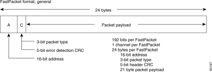
All FastPackets have a similar 3-byte header that is monitored by almost every card in every IPX node. The address is the destination address of the packet that defines the route to the far end node as well as the terminating card in the far node.
The packet type defines the content of the packet and the CRC is a cyclical redundancy check of the three header bytes to detect any corruption of these bits. The remaining bits in the packet are used to carry payload data. The various packet types may have additional overhead bytes and will be described later.
There are six main packet types. They are identified by a 3-bit packet type code following the packet address. Packet types are summarized as indicated in Table 9-1.
| Queue | Traffic types |
|---|---|
High Priority | NPC/PCC, First 2 packets of voice |
Non-Time-Stamped Data | Data > 56 Kbps, "a", "t" voice, modem |
Time-Stamped Data | Data £ 56 Kbps |
Voice, PCM and ADPCM | "c", "v" voice |
Bursty Data without ForeSight | Frame relay |
Bursty Data with ForeSight | Frame relay |
Highest priority is given to system control packets and initial bursts of voice packets. These high priority type packets are queued with priority over any other packet type and pass through the network with minimum delay. Cards that generate high priority packets are the NPC and CDP.
High priority packets (Figure 9-2) are generated by the NPC to communicate with other nodes in the network for system-level message interchange. To make this overhead message channel as robust as possible, control fields are added to the header. The receiving NPC checks that all packets received in a message are in sequence. If a packet is missing, the receiving NPC requests a retransmission of that packet. Also, a second CRC byte is added to the end of the packet to perform error-checking on the 20-byte NPC packet message.
Initial voice packets, or talk-spurt packets as they are sometimes referred to, are also transmitted with minimum delay. This is to establish a minimum delay datum for filling the null-timing buffers in the far end packet receivers.

With the exception of the first two packets of voice, which are sent via high priority packets, digitized voice channel information from circuit lines is carried in the voice packet type (Figure 9-3). Voice packets have a 168-bit payload message field. PCM-encoded packets carry twenty-one 64 Kbps (8-bit) PCM samples in this message field.

In most cases, the voice channels will be compressed by a factor of either 2:1, 3:1, 4:1, or 8:1 by the CDP card to increase the transmission efficiency. This is illustrated in the ADPCM voice packet format, which can carry 42 compressed voice samples with 32 Kbps compression, 56 samples with 24 Kbps, or 84 samples with 16 Kbps compression. Consider also that many of the voice channels will contain "silence" that will be discarded by the Voice Activity Detector algorithm resulting in no packets being sent.
The "one's density" requirement for T1 lines (packet line) is inherent in 32 Kbps, 24 Kbps, and 3-level 16 Kbps ADPCM (c16 type) so any T1 facility can be used to transmit this code. However the 4-level 16 Kbps ADPCM (c16z type) may require a clear channel T1 or E1 facility. The CDP generates this packet type.
Most data at rates over 56 Kbps is sent using non-timestamped data packets (Figure 9-4). The packet payload is filled up with 21 data bytes data from a queue associated with a particular data channel. The data is loaded in a first-in, first-out (FIFO) basis and when the packet payload is full, the FastPacket is transmitted to the destination node.

The structure of the data words in the packet message may be one of several types:
The data frame formats for these various types of non-timestamped packets are illustrated in Figure 9-5 and described in the following paragraphs.
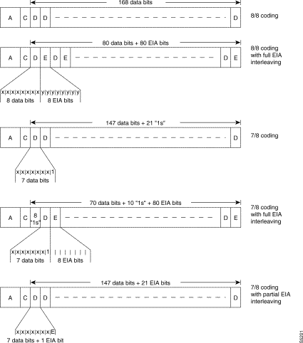
The 8/8 coding can be specified in the software for data channels that carry data whose protocol ensures that there are no long strings of zeros in the data. For this data, the packet message carries 168 data bits. EIA control leads are sent in separate packets only when a change of state on one or more control lead is detected (referred to as non-interleaved data). The data bits are inverted by the IPX when 8/8I encoding is specified, and is used when the data protocol (such as SDLC) never uses the "FF" character.
Another format that can be specified is the 7/8 coding. This coding is used when there is no checking for zeros by the connecting data device and there is possibility of long strings of zeros. With 7/8 coding, only the first 7 bits of the message byte carries data, the eighth bit is always forced to a one and gets discarded at the far end. If E1 or subrate packet trunks only are used or if the NTC using B8ZS is used to carry these non-timestamped data packets, the 8/8 coding may be used.
Non-timestamped data is also used by voice circuits that do not employ VAD. These channels are likely to carry data from voice/data multiplexers or from high-speed modems or FAX machines.
Non-timestamped data packets are generally given priority behind high-priority packets and are characterized by low but variable delay. The variability in delay is removed in buffers at the far end IPX so each channel experiences a consistent amount of end-to-end delay. IPX cards that use non-timestamped data include the SDP and CDP.
Timestamped data packets (Figure 9-6) have a 1-byte timestamp field leaving 20 bytes for user data. The timestamp is set by software to a maximum allowable delay figure (typically 40 ms.). This timestamp is checked at every node by the NTC to set the priority of the packet in the outgoing queue. If the packet has accumulated more delay than the maximum indicated in the timestamp, the packet is discarded. If this happens, the user device will have to retransmit this data.

Timestamped data packets generally have low priority in queueing. However, packets with older timestamps are given higher priority with the various packet line queues. Over a network path with multiple hops, timestamped data generally experiences longer delays than non-timestamped data.
The timestamp is used to reduce the worst case maximum data delay by giving older packets priority. This is especially useful for data channels operating at less than 56 Kbps that might otherwise encounter excessive end-to-end delay when sent over links of five or more hops. There is additional overhead to timestamped data packets. But when the channel data rate is reasonably low, the additional overhead is not so much a penalty.
All of the packet structures described for non-timestamped data, 8/8, 7/8I etc., are applicable to timestamped data. In addition, there is provision for partially interleaved data. This is a modification on the 7/8 coding with Fast EIA described in "Interleaved (Fast EIA) Control Leads" section in Chapter 14, Synchronous Data Connections. With partially interleaved data, each message byte consists of seven data bits followed by one EIA control lead in the eighth bit. The control lead to be sent with the data is specified by the user. All other EIA control leads are sent in a separate packet as is done for the non-interleaved data.
All Data Frame Multiplexed (DFM) data connections (64 Kbps and below) are timestamped. DFM discards data packets that contain a repetitive data pattern (up to 15 consecutive packets can be discarded) at the transmitting node. The receiving node needs to know how many packets were discarded so it can recreate the packets and maintain the integrity of the transmitted data. For these packets, the timestamp byte is used to specify a sequence number, indicating the number of suppressed packets. Data channels using DFM are prevented from using fast EIA option. Timestamped data packets are generated by SDP, LDP, and CDP cards.
The frame relay data packet format (sometimes called bursty data) is similar to the timestamped data format. The forth byte is now used by the frame relay data format for a second control byte (C2) as shown in Figure 9-7. The first four bits of this control byte contains a code indicating whether this packet is the start of the frame relay frame, the end, or one of the frames in the middle. Two bits are reserved for congestion control. The last four bits of this control byte is the hop count. The remaining 20 bytes is payload frame relay data as shown in Figure 9-7.

Idle packets from an NTC are only four bytes long since the framing is based on the CRC in the header rather than the T1 frame bit. NTC idle packets start with the first byte filled with all ones followed by three bytes such that a valid CRC is contained in the third byte as is found in a normal packet. The following message byte contains a hex DD. The repeating four-byte idle packet pattern contains only a moderate ones density and puts a minimum stress on the repeatered packet line.
Packet framing for NTC packet trunks is based on the CRC code rather than either the T1 or E1 framing. Since idle packets are short, recovery from an out-of-frame condition is faster on an NTC packet line. In this condition, almost all packets will be idle and, since they are short packets, the CRC will repeat much more often speeding up the reframe process.
Remote alarm packets are used to transmit the yellow alarm code to the node at the far end of the packet line. They are similar to idle packets and have the same all ones initial byte and a valid CRC. The message byte pattern, a hex DB, is unique to the remote alarm code. The remote alarm packets are used only with the NTC.
The following paragraphs describe the digital line format for various types of digital transmission lines used to transmit FastPackets throughout StrataCom networks. These lines operate at data rates of typically 2 Mbps and less and are referred to as narrowband in contrast to trunk rates described previously.
Refer to Figure 9-8, which illustrates a very simple three-node network. As indicated on the figure and by definition, lines connect local sources of digital data and terminate on the IPX. These sources of digital signals may include digital FastPADs, PABX's, and D4 channel banks for voice transmission and Data Terminal Equipment (DTEs), bridges, routers, video compression devices, or AT&T Digital Data Service® lines for data transmission.
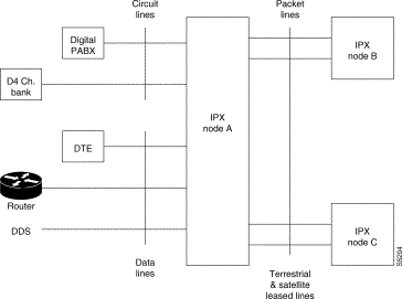
The IPX node connects these local sources of data to the digital transmission lines of the long-haul, high-speed, digital networks of various telecommunication common carriers for transmission to other nodes at locations around the country or around the world. This may be accomplished using terrestrial lines of copper, fiber optics, or digital microwave radio. Often, for international circuits, satellite links are used.
One of the main purposes of the IPX is to condense the data and transmit it more efficiently over these lines. This is accomplished by packetizing the incoming data before transmitting it. Packet lines, as the term is used in this application, are digital transmission lines, carrying packetized data in the form of FastPackets, connecting the various nodes.
In digital transmission systems using the AT&T defined digital hierarchy, both circuit lines and packet trunks are T1 and fractional T1, and T3 transmission lines. In locations employing the CEPT standards, E1 digital transmission lines are used. Packet trunks connect to the network side of the IPX whereas circuit lines connect to the customer side of the IPX. In addition to the connection point, the primary difference between circuit lines and packet trunks is in the format of the transmitted data on these lines.
In summary, packet trunks are used to link IPX nodes together in a network configuration and use FastPacket frame formats for the data. Circuit lines are used to interface the IPX to customer equipment or circuits using one of several industry-standard digital transmission data formats.
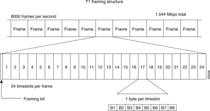
T1 lines transmit data at 1.544 million bits per second (Mbps). This is called the Digital Signal Level 1 (DS1) rate. To keep the transmitting and receiving devices at each end of the line synchronized, a framing bit is periodically inserted in the data stream (see "T1 Packet Trunks" section). This framing bit is given a unique pattern that is easily recognized by the terminating equipment. The data bits between each framing bit is referred to as a frame. On a T1 line, there are 8000 frames/second with each frame consisting of 193 bits (192 bits of data and one framing bit).
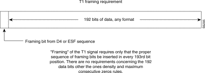
T1 transmission networks are not concerned with the actual channelization of the T1 signal, only with the frame bit. Packet lines use these 192-bit T1 frames in a somewhat different manner by organizing them into a 192-bit FastPacket format. A FastPacket is a group of 192 bits and on a T1 line the FastPacket is aligned with the 192-bit D4 frame. Of the total 1.544 Mbps available with a T1 line, 1.536 Mbps is available for transmitting user data as there are 8000 framing bits per second overhead.
On T1 circuit lines, the data in each frame is organized in a standard format (Figure 9-10). There are twenty-four bytes of data, each byte consisting of 8-bits. Frames of data are transmitted 8000 times a second. Each of the 24 bytes represent a single customer voice channel or data channel. These channels operate at a rate of 64 Kbps each are referred to as DS0 channels. The channels in this format, called D4 frame format, are numbered in a numeric sequence 1 through 24. The start of each frame is a single framing bit that defines the start of channel 1.
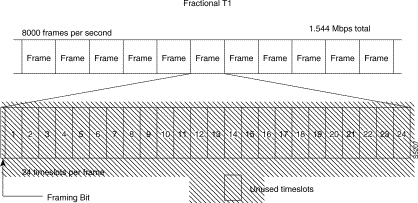
Fractional trunks have the following characteristics:
When using a fractional T1 trunk, a FastPacket is sent in 24 consecutive channels, regardless of how many frames are spanned in the process. In Figure 9-11, the fractional T1 line will support user data in 12 of the 24 bytes in each frame. In this example, it will take two frames to transmit a full FastPacket. Fractional T1 is used when only a limited capacity is required between some nodes such as a tail circuit node.
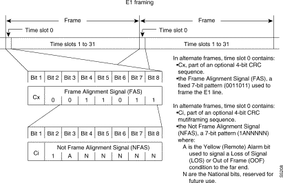
In many international locations, the CEPT E1 is commonly used for digital transmission lines. E1 lines can also be used as narrowband trunks. While the 8-bit byte is still used, as in T1 lines, the bit rate, the number of channels and the frame format differs between the two lines. E1 lines carry 30, 31, or 32 channels at a transmission rate of 2.048 Mbps.
There are 32 channels in the E1 frame as shown in Figure 9-12. Channels are generally numbered from 0 to 31 with channel 0 reserved for frame alignment and CRC error checking. Channel 16 is used to carry circuit signalling information in many (but not all) applications and often cannot be used for customer data. However, all other channels 1-15 and 17-31 may be used for user data. The E1 frame size is 8 bits/byte X 32 bytes = 256 bits.
Since the E1 frame size is not the same as it is with T1 or with a FastPacket, the FastPacket frame boundaries are not aligned on an E1 line as they are on a T1 line. For earlier IPX systems, it was convenient to use the T1 framing bit to synchronize not only the T1 line but the FastPacket. This cannot be used in the E1 world so a different method of framing is used for both E1 and T1 in current IPX systems. Refer to the "Packet Framing (NTC)" section for further details.
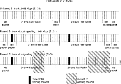
The 24-byte FastPacket format cannot be changed but the 192 bits are transported in all available user transport bits in the E1 line. To determine where the FastPacket begins and ends, a synchronizing technique is used that looks at all user data bits for a valid FastPacket CRC code. When this is located among all the user data bits, the IPX now knows where the start of the FastPacket frame is and ignores the E1 frame synchronizing information.
On most E1 lines 30 channels are available for FastPackets. These lines are referred to as E1/30. There are 1.920 Mbps available for FastPacket data versus 1.536 Mbps available with T1. If channel 16 is not used for signalling (E1/31), it is available for data bringing the available data rate up to 1.984 Mbps. On a totally unframed E1 line (E1/32), the full 2.048 Mbps. data rate can be used for FastPackets (Figure 9-13).
Subrate lines can also be used as a packet trunks. Subrate lines usually utilize a portion of an E1 or T1 transmission facility (see Figure 9-14). They are available mainly in Europe and other international locations, but in North America they are used for special purposes such as satellite hub access. Subrate trunks, like fractional T1 trunks, are used when only a limited capacity is required between some nodes such as a tail circuit.

Subrate packet trunks function like a synchronous data circuit and operate at specified data rates from 64 Kbps to 1.920 Mbps. A penalty in using the lower rates is that the network overhead becomes a significant percentage of the overall transmission rate.
Unlike T1 and fractional T1 trunks, subrate trunks carry their own clock with the data. As such, the BC-SR card synchronizes to the subrate trunk with looped clock. Allowed clock rates are: 64 Kbps, 128 Kbps, 256 Kbps, 384 Kbps, 512 Kbps, 768 Kbps, 1.024 Mbps, 1.536 Mbps, and 1.920 Mbps. In addition, there is no frame format in the subrate trunk and no framing bit(s) defined. The IPX uses its own proprietary synchronizing technique to synchronize end-to-end transmission on subrate trunks.
IPX cards that are used to interface to subrate trunks are the NTC and the BC-SR back card. The subrate trunk is always a DCE so the IPX BC-SR is configured as a DTE as indicated in Figure 9-14. Three interfaces, V.11/X.21, V.35, and MIL188/RS-449, are available with the BC-SR card. Most of the standard EIA RS-232 and ITU-T V.35 type control leads are supported and can be monitored and/or conditioned.
The receive clock is monitored for out of range or clock loss. Because data timing is carried on separate clock leads along with the data, there is no requirement for sufficient ones density as in the T1 packet trunks.
The NTC uses a unique StrataCom frame acquisition algorithm for providing end-to-end data transmission synchronization independent of any of the standard digital line frame formats previously discussed in this chapter. This is the reason the NTC will operate with various types of line interface (back) cards such as the BC-T1, BC-E1, and BC-SR.
With the NTC mode of packet line framing, the concept of line framing and packet framing have been disassociated. A FastPacket may start at any byte boundary of the standard E1 or T1 line format. Even a line that is completely unframed (for example unframed E1 lines or subrate lines) can be used for a packet line. Unframed lines provide no byte boundaries; they act just like a large data pipe. In these cases, a FastPacket can begin at any arbitrary bit position.
Refer to back to Figure 9-10, illustrating the general FastPacket data format. All FastPacket types have a 2-byte address code followed by a 1-byte packet type and CRC for these bytes only. NTC framing is done by searching for a four-byte sequence in which the third byte contains a valid CRC for the sequence. The four-byte sequence instead of a three-byte sequence was chosen to accommodate FastPacket types that contain certain information in the fourth byte.
With this framing mode, it is no longer necessary to use a full 24-byte idle packet on the packet line any time there is no FastPacket ready to send. Consequently, the NTC uses a 4-byte idle packet that reduces the queuing delay of a FastPacket in the NTC.
Occasionally a packet trunk will have a large percentage of the available bandwidth filled with idle packets. In order to reduce the negative effects of a repeating 4-byte pattern on the packet line, there are four different idle packet codes that are used in sequence. Each packet starts with a hex "FF" followed by three bytes such that a valid CRC is contained in the third byte.
If the receiving node loses track of the CRC (causing it also to lose frame sequence), it issues a Loss of Packet alarm to indicate the packet line is no longer serviceable. If this occurs, the far node is notified of this failure by transmitting a remote alarm code. If the failure happens to be a one-way fault, the remote alarm code makes certain the far node will avoid using this packet line and reroute traffic to another. If the problem is a two-way fault, the far end will already have detected a Loss of Packet Frame on its own and will have already initiated a reroute.
There are four additional packet codes used to send a remote (yellow) alarm to the far end node when a failure on the incoming direction of the packet line is detected. These packets also start with the hex "FF" in a manner similar to the idle packets. Both idle packets and remote alarm packets are discarded at the far node since they contain no customer data.
Because the NTC framing does not depend on any transmission media protocol, it is very easy for FastPackets to travel along a number of different interconnecting trunk types on hops that may span many different physical level trunks. There are no protocol converters required to pass from a subrate tail circuit, for example, to a full trans-continental T1 or even T3 toll trunk.
![]()
![]()
![]()
![]()
![]()
![]()
![]()
![]()
Posted: Thu Jan 18 12:55:46 PST 2001
All contents are Copyright © 1992--2001 Cisco Systems, Inc. All rights reserved.
Important Notices and Privacy Statement.