|
|

This chapter is provided for users who wish to have an in-depth knowledge of the IPX/IGX synchronous data connections and related functions. It describes the basic flow of information through the network for various data connection types. It also describes the data compression features, data clocking, and data channel conditioning available.
The chapter contains the following:
The types of synchronous data connections available include:
Point-to-point high-speed synchronous data connections interface to the IPX on Synchronous Data PAD (SDP) cards that transmit at rates from 1.2 Kbps to 1.024 Mbps. These connection types are used for direct computer-to-computer transfer of large files. Up to four ports per card are supplied interfacing data, clocking, and control leads.
For more efficient transmission of multiple low-speed data circuits (up to 19.2 Kbps), the Low-speed Data PAD card is used. It can interface both synchronous as well as asynchronous data, typically from data terminals, point of sale terminals, etc. A special version of the LDP is used to interface with common carrier 56 Kbps DDS circuits in the US. Four or eight ports per card are supplied interfacing data, clocking, and control leads.
Channelized data connections using T1 or E1 connections are interfaced to the IPX by using the Channelized Data PAD (CDP) card. These connections use individual or multiple DS0's to provide data connections operating at rates from 56 Kbps to 512 Kbps. and provide a direct interface with user's data submultiplexers, voice/data multiplexers, and other data devices that operate over T1 or E1 lines.
Channelized data connections fall into two categories, subrate and superrate. Subrate data connections consist of multiple low-speed data logical connections sub-multiplexed into a single 64 Kbps DS0. Common multiplex standards include DS0A and DS0B for T1 and X.50 for CEPT E1. DS0 subrate data rates cover the range of 2.4, 4.8, 9.6 and 56 Kbps. IPX systems with a CDP card will accommodate one subrate data channel per DS0 channel and DS0A signalling.
A superrate data connection (sometimes called bundled connection) consists of a single data circuit that spans multiple DS0s, up to a maximum of eight. Superrate connections are available as aggregates of 56 Kbps or 64 Kbps up to 512 Kbps on a CDP E1 or T1 port. All bits transported are considered data bits, because no supervision or control bits are imbedded in the data stream. Superrate 56 Kbps bit streams are bit stuffed up to 64 Kbps by the external multiplexer by inserting a "1" in the first or last bit position (user selectable) of the data byte. The CDP extracts and discards this bit for packet transmission and reinserts it at the far end Nx56 connection.
There are two transmission modes for subrate data connections: interpretive and transparent. In the transparent mode, the IPX does not look for any supervisory or control information in the data stream; it assumes all bits are data bits. The interpretive mode, on the other hand, expects that the data stream from the customer includes some supervisory bits and the CDP must do some processing to extract this supervisory information.
CDP to CDP connections always run in the transparent mode. CDP to SDP or LDP run in the interpretive mode as these channels provide separate control lead inputs and outputs. Supervisory signals in the DS0A mode are distinguished from data signals in interpretive mode connections. Some of the features available with the SDP/SDI and LDP/LDI cards are not available on the CDP with the subrate or superrate connections. These include isochronous clocking, fast EIA, and Data Frame Multiplexing.
Figure 14-1 illustrates a hypothetical IPX network with six nodes, all of which are equipped with a CDP, to illustrate the various types of data connections possible. At nodes zeta and eta, there are two mainframe computers that need to exchange bulk data. Each is equipped with a front end processor for high-speed data transfer with its own high-level protocol. Each has a DS1 interface to the BC-T1 back card associated with the CDP.
If the full bandwidth of the DS1 is not required for this computer-to-computer link, groups of DS0s can be bundled together to provide Nx56 or Nx64 Kbps virtual circuits on each CDP up to 512 Kbps each. This requirement for only part of the full DS1 could be accommodated by a fractional T1 circuit interface.
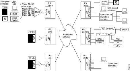
At Node alpha, the CDP is serving as the IPX interface to a customer's multiplexer which, in turn, is fed by a variety of sources: low-speed (RS232) terminals, high-speed computer links, synchronous DDS data (from a DSU), and high-speed synchronous data from a video codec. Node alpha is capable of supporting connections with all of the other nodes.
The CDP supports channelized data connections. For example, node alpha routes 256 Kbps data from a video codec to node beta where the data is terminated by an SDP with an appropriate SDI back card. The 256 Kbps data connection is presented to the CDP by the multiplexer as a bundle of four DS0 timeslots, yet it terminates on an SDP as a serial, synchronous V.35 data port.
Note that to support clear channel Nx64 Kbps connections such as this, the multiplexer feeding node alpha must enforce the one's density requirement with B8ZS (T1) or HDB3 (E1) coding. Otherwise, the connection could be carried as Nx56 Kbps with the multiplexer providing the bit stuffing. Or one could use alternating 64 Kbps channels with ones density requirements met in unused channels.
Likewise, the packet trunks connecting node alpha and node beta must guarantee transparency to packets that require either B8ZS trunk lines or some form of transparency encoding. This can be either 7/8 ths or 8/8 ths-inverted encoding. The 7/8 ths coding stuffs an extra one bit into each byte. The CDP will discard these extra bits prior to packetization. Note that the 56 K bit stuffing at the port interface is separate and independent of the 7/8 bit stuffing on the packet trunk.
Another example of data connectivity is the connection of the computer at node alpha with the synchronous terminal at node beta. The remote end is terminated by another SDP data port and connected to a cluster of synchronous data terminals via a multidrop modem.
An example of interconnectivity with the DDS network is presented between node alpha and node gamma. The DDS connection is presented to the CDP as a single DS0 timeslot carrying 56 Kbps of useful information. This illustrates a typical "tail" DDS circuit. The LDP4/DDS at node gamma is used to connect to the DDS network with two of its four ports as well as provide other local DSU connections.
Another data connection illustrated is the low-speed (RS232) asynchronous data connection. This enters node alpha as Sub-Rate Data Multiplexed (SRDM) timeslots, in which a single DS0 can carry one or more low-speed channels. The CDP DS0A currently carry only a single data channel regardless of operating speed. The LDP at node delta terminates these bundled data connections as individual low-speed data ports. This obviates the need for a separate multiplexer at node delta as is used at node alpha.
Digital Data Service (DDS) circuits can be obtained from AT&T and other common carriers to provide domestic customers with nationwide data connections over switched public T1 networks. These DDS trunks operate synchronously at rates up to 56 Kbps and have imbedded maintenance and configuration commands available. These DDS circuits can be used to extend data service to users who are not served directly by an IPX network.
The IPX provides a direct interface to the AT&T DDS network using the LDI4/DDS back card and LDP, Model B or later front card. Each LDI/DDS provides four DDS ports, each of which can be configured to act as either a Data Service Unit (DSU) or an Office Channel Unit (OCU). The LDI is software configured to operate at a selected synchronous data rate of between 2.4 and 56 Kbps.
When an LDI/DDS port is configured as a DSU, it provides a 4-wire DDS circuit connecting point. The port acts like a DTE using external clocking since the LDI must be synchronous with the DDS network timing. This circuit terminates on a OCU inside the serving central office providing the access point to the DDS network.
This is illustrated in the top two circuits in Figure 14-2. The DDS circuit may be a point-to-point connection (#1) from OCU to OCU or a multipoint connection, using a Multiple Joint Terminator (MJT), which connects several terminating circuits together.
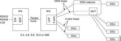
An LDI/DDS port can also be configured as an Office Channel Unit to terminate a local data user over a DDS-type data circuit. This circuit connects point-to-point to a remote DSU and associated user device over privately-owned non-loaded lines. This is illustrated in the bottom two circuits of Figure 14-2. In the OCU mode, the port acts like a DCE and loops the timing back to the local DSU. The DSU permits the user to be located several miles from the IPX and provides DDS-type loopbacks for testing.
For example, in Figure 14-2, a remote user of node beta may come into the IPX on port #3 then be connected to the DDS network off port #1 to communicate with another user who may be thousands of miles away. The allowable distance from the IPX to the remote DSU ranges between approximately 3 to 30 miles depending on operating bit rate and cable gauge of the telephone cable.
An alternate method for a user located adjacent to an IPX node to access the DDS network is by using a SDP front card and associated SDI back card at the local node. The user device must be located within the nominal distance restrictions of RS-232, RS-449, or V.35. The packet network, in turn, interfaces with the public switched network at this or any other node using a 56 Kbps circuit. The SDP must be configured to supply timing to the local user device as it must ultimately be synchronized to the DDS network.
This is illustrated in the circuit between the two IPX nodes in Figure 14-2. An originating user device, colocated with an IPX, interfaces to node alpha using the SDP/SDI. At node beta, there is an interface to a DDS office using an LDP and LDI/DDS operating as a data service unit. The IPX network is configured with a 2.4, 4.8, 9.6, or 56 Kbps data circuit between the two nodes.
The following paragraphs describe the block diagram signal flow for the various synchronous data circuits through the IPX network.
Data connections processed by the CDP terminate on the BC-E1 or BC-T1 backcard (CDP does not operate with a BC-SR, SDI, or LDI backcard) which stores DS0 timeslots separately in a receive frame buffer. A Local Bus (LB) is required between the CDP card and the back card. When a complete frame of data has been received, it is forwarded to the CDP for processing (Figure 14-3).
The processing performed in the CDP depends on the circuit specifications entered by the user and may include bit stuffing, data inversion, or timeslot resequencing. For subrate channels, the data processing may also include extracting supervisory bits, signalling conversion, and detection and synchronization to the subrate frame pattern.
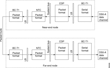
The CDP demultiplexes the subrate frame pattern and extracts individual channels. Each subrate data channel is processed and transported as separate logical channels in the IPX network. The CDP can handle a maximum of 32 individual logical connections.
The processed data is packetized, queued for transmission, and then written to the system bus. Supervisory data bits are packetized separately from user data and applied to the system bus. These packets are pulled from the system bus by either an NTC if the data destination resides on another IPX node or another CDP for an intranode connection.
At the receiving node, packets for superrate (bundled) connections are extracted from the system bus and buffered. Higher rate channels (64 Kbps and above) in general do not use timestamped packets and, as such, are buffered and pass directly to signal processing. The processing is the inverse to that done to the data on the transmitting end. After processing, the data is immediately assembled into a frame, along with samples from other connection types, and sent to the associated back card where the frames are played out into corresponding timeslots on the circuit line to the user device.
Subrate channels are lower speed and are often timestamped. These packets are transferred through the receiving end CDP according to the timestamped packet synchronizing algorithm with buffering to compensate for variable network delays. After processing, the individual subrate channels are multiplexed into a single DS0 timeslot. A data frame is accumulated then and to the back card.
Data connections may also be read off the system bus by a SDP or LDP depending on the connection type. The signal flow is essentially the same except the supervisory packets can be translated into control lead status at the corresponding SDI or LDI back card.
Interface to the IPX for circuits from customer synchronous data devices use the SDP or LDP card and associated SDI and LDI interface card. Customer data and associated control lead information from various devices are transmitted to the IPX on data lines with standard data interfaces (for example RS232, V.35, RS449/X.21). The SDP card is connected to the back card via a SDP Utility Bus (SDP-UB). The LDP card is connected to the back card via a Local Bus (LB). Figure 14-4 illustrates the signal flow diagram for synchronous data.
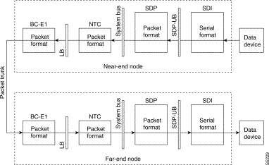
Depending on the user data device and its operating speed, data will be received by a Synchronous Data Interface (SDI) card, as shown in Figure 14-4, a Low-Speed Data Interface (LDI) card, or a Frame Relay Interface (FRI) card. The data back card provides the physical interface.
A plug-in daughter board allows the back card to present DCE or DTE interfaces independently on each channel. Clocks may either be taken from the user's equipment (at either end of the connection) or provided by the IPX as a submultiple of its system clock.
Data interface cards all perform a similar function of monitoring the transmit data and control leads, serial to parallel conversion of the data, level shifting, and, in the case of balanced data leads, converting to unbalanced logic signals. The data is forwarded to one of the Data Packet Assembler/Disassembler (PAD) or service interface cards over a utility bus connecting the interface card to the PAD card.
Again, depending on data type, the Data PAD card may be one of the following: Synchronous Data PAD (SDP) or Low-Speed Data PAD (LDP). All input data is treated as synchronous data. If it is low-speed, asynchronous data, the LDP oversamples it to make it synchronous (the bit rate is generally set to five times the asynchronous data rate).
The Data PAD cards provide transmit clock, either normal, looped, or split, to the external data device to clock in the data. The SDP buffers the data to permit isochronous operation. Repetitive patterns in the incoming data are suppressed with a feature called Data Frame Multiplexing (DFM) and assembled into packets of up to 168 bits with a destination header.
The packets are applied to specific timeslots on the TDM MUXBUS portion of the system bus where they are picked off by a NTC or AIT trunk card associated with the proper destination code as previously described for voice packets. From this point on, the data packets are treated just like voice packets. The trunk cards do not mix voice and data in a packet queue. There are separate queues for voice and the various types of data.
Generally, a packet is not sent until its payload is full. But since low-speed data does not fill up its queue very rapidly, it is quite likely that there might be long delays in sending the data. Because of this, low-speed data circuits can be assigned a timestamp that is used to limit the delay in sending these packet types.
At the far end, the flow is the reverse. The packet is received by an NTC card, then sent via the system bus to the receiving data card. Here, it is read off the bus into a receive buffer, allowing for clock and transmission fluctuations, and then clocked out as serial data on the back card connector.
The Data PAD card is a physical-layer device, and relies on the user's equipment to handle errors by retransmission. Packet headers are checked for CRC in the NTC card, and corrupted packets discarded, but the data stream out of the IPX may contain errors or missing bits. The data PAD does not detect these conditions or retransmit to correct them.
Data channel control lead status is transmitted through IPX networks in one of three data channel signalling connection types:
Refer to description of FastPacket data packets in the "Non-Timestamped Data Packets" section of Chapter 9, FastPackets and Narrowband Trunks, and Figure 14-5 illustrating these three modes. The data back cards allow up to 12 data control leads per data circuit to be sampled and transmitted to the far end of the connection. The choice is dependent on DCE-DTE options and software configuration.
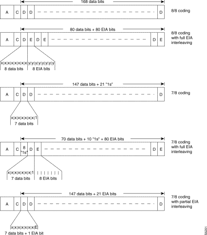
For non-interleaved connections the IPX treats up to twelve control leads impartially, any signal received on a control lead pin at one end may be transmitted to any pin at the other end either directly or with translation. Therefore, it is possible to have different interfaces for the same connection (for example V.35 to RS449). Table 14-1 shows equivalent names and pins for RS-232, RS449 and V.35.
| Src | Name | V.35 | RS449 | Pin | RS 232C | Pin | RS 232D | Pin | Function | Fast EIA |
|---|---|---|---|---|---|---|---|---|---|---|
DTE | TXD | P/S | SD | 4/22 | BA | 2 | BA | 2 | XMT Data from DTE | no |
DCE | RxD | R/T | RD | 6/24 | BB | 3 | BB | 3 | RCV Data to DTE | no |
DTE | RTS | C | RS | 7/25 | CA | 4 | CA | 4 | Request to Send | F4 |
DCE | CTS | D | CS | 9/27 | CB | 5 | CB | 5 | Clear to Send | F4 |
DCE | DSR | E | DM | 11/29 | CC | 6 | CC | 6 | Data Set Ready | F3 |
DCE | DCD | F | RR | 13/31 | CF | 8 | CF | 8 | Carrier Detect (RLSD) | F7 |
DCE |
|
|
|
|
| 9 |
| 9 | Positive Test Voltage | no |
DCE |
|
|
|
|
| 10 |
| 10 | Negative Test Voltage | no |
DCE | QM |
|
|
|
| 11 |
| 11 | Equalizer Mode | no |
DTE | pin 11 |
|
|
|
| 11 |
| 11 | Sometimes used for data | no |
DCE | SDCD |
| SRR |
| SCF | 12 | SCF | 12 | Sec. Carrier Detect | no |
DCE | SCTS |
| SCS |
| SCB | 13 | SCB | 13 | Sec. Clear to Send | no |
DTE | STxD |
| SSD |
| SBA | 14 | SBA | 14 | Sec. XMT Data | F5 |
DTE | NS |
| NS | 34 |
| 14 |
| 14 | New Sync | F7 |
DCE | TxC | Y/a | ST | 5/23 | DB | 15 | DB | 15 | XMT Clock | no |
DCE | SRxD |
| SRD |
| SBB | 16 | SBB | 16 | Sec. RCV Data | F5 |
DCE | RxC | V/X | RT | 8/26 | DD | 17 | DD | 17 | RCV Clock | no |
DCE | DCR |
|
|
|
| 18 |
|
| Divided RCV Clock | no |
DTE | SRTS |
| SRS |
| SCA | 19 | SCA | 19 | Sec. Request To Send | no |
DTE | DTR | H | TR | 12/30 | CD | 20 | CD | 20 | Data Terminal Ready | F3 |
DCE | SQ |
| SQ | 33 | CG | 21 | CG | 21 | Signal Quality Detect | no |
DCE | RI | J | IC | 15 | CE | 22 | CD | 22 | Ring Indicator | F2 |
DTE | SF |
| SR,SF | 16 | CH | 23 | CH | 23 | Signal Rate Select | no |
DCE | SI |
| SI | 2 | CI | 23 | CI | 23 | Signal Rate Indication | no |
DTE | XTC | U/W | TT | 17/35 | DA | 24 | DA | 24 | External XMT Clock | no |
DTE | BSY |
| IS | 28 |
| 25 |
|
| Busy (In Service) | F1 |
DTE | LL |
| LL | 10 |
|
|
|
| Local Loopback | F2 |
DTE | RL |
| RL | 14 |
|
| RL | 18 | Remote Loopback | F6 |
DTE | TM | K | TM | 18 |
|
|
|
| Test Mode | F6 |
DTE | SS |
| SS | 32 |
|
|
|
| Select Standby | no |
DCE | SB |
| SB | 36 |
|
| TST | 25 | Standby Indicator | F1 |
In the non-interleaved mode, the leads are sampled at a rate set by the operator. If there has been a change since the last sample, the front card assembles a supervisory packet of the same type as the connection's data packets and transmits it to the far end. There the packet is processed by the data front card and the new states of the leads latched onto the outputs.
Because the EIA packetize path is separate from the data path and control leads are sampled every 50 msec. maximum (20 times/sec), the synchronization between control lead and data changes is accurate only to the update interval +50 msec. (100 to 1050 msec).
The non-interleaved mode is the most efficient as far as packet trunk bandwidth utilization is concerned. FastPackets carrying control lead information are sent only sporadically and the payload has plenty of room for control lead status from a number of data channels. However, the delay between far end receiving data and the corresponding control lead change of state at the transmitting end is quite large.
When interleaved ("Fast") EIA connections, are specified, up to seven leads may be updated at the interleaved rate. The control lead status change is tied very closely to the data (within 1 byte interval). Combinations of control leads for both IPX data channel as DCE or DTE are listed in Table 14-1 in the Fast EIA column. The remaining control leads may be sent as non-interleaved at 0-20 updates/sec. With interleaved EIA connections, there is a trade-off between the control lead update rate and packet trunk bandwidth as 50 percent of the FastPacket payload is taken up with control lead bytes.
Any input pin designated F(n) in Table 14-1 may be mapped to an output pin with the same F(n) up to a maximum of 8 pins in the "Fast EIA" column. With fast EIA connections, only some combinations of EIA lead correspondence are carried by hardware and synchronized to the data:
The SDP/LDP supports secondary channel features by treating the signals as EIA leads. These signals are available for interleaved EIA connections, so the maximum rate is from 5 percent to 2.5 percent of the primary connection, depending on configuration.
The partially interleaved or embedded EIA mode is a compromise between the non-interleaved and interleaved modes and is used for DFM data. The partially interleaved mode allows one bidirectional control lead (RTS if DCE or CTS if DTE) to be encoded as the eighth bit in each data word, providing quick control lead response without significantly affecting bandwidth requirements. The remaining control leads go as separate packets as in non-interleaved mode.
This mode is used for data 19.2 Kbps and under and is not available for DDS trunks. The data must be specified as 7/8 coding to reserve the eighth bit for the selected control lead and requires zero suppressed trunks using B8ZS or HDB3 coding. Table 14-2 lists the functions that the LDP Embedded EIA mode supports.
| Features Supported | Features Not Supported |
|---|---|
Bidirectional RTS/CTS leads. | Delayed RTS/CTS loopback feature is not available. |
Control lead tracks the data within 24 bit intervals. | Connections with 7 or 16 bit pattern matching is not supported. |
Data rates up to 19.2 Kbps. | 8/8 bit coding is not supported. |
DFM bit pattern matching. | DDS trunks. |
7/8 coding. |
|
Control leads may be held high or low or change to follow any control lead input from the far end of the connection. Also, conditioning of the control leads by the IPX can be specified for when the connection has failed or is looped for maintenance. Conditioning is specified by the Interface Control Template (ICT) in software and is set by the user.
It is also possible to configure local lead changes depending on local inputs. This is done in hardware, so there is almost no delay. The valid configurations for local conditioning are any control lead to any output control lead. When remote CTS is controlled by the local RTS the user may program a delay of from 1 to 255 milliseconds.
Data compression, sometimes called Data Frame Multiplexing (DFM), is used in the SDP, LDP, and FRP to reduce the bandwidth requirements for most types of low-speed data connections. It is not currently employed by the CDP for subrate or superrate data.
For DFM to be applied to a connection, four conditions must hold as follows:
The expected pattern length must be set in software for DFM to work correctly. It should be set to the number of bits in a character of the user's protocol, since repetitive idle codes are the patterns normally suppressed. Normally, both directions of a connection use the same protocol, so the pattern length in each direction should be the same. In nearly all cases, the pattern length should be 8 bits.
The transmitting front card uses the sequence field in the packet to indicate the position the packet should be placed in the receive buffer. The receiver can tell from the sequence how many packets have been suppressed since the last received, and therefore reconstruct the data stream.
Even if the data stream is entirely repetitive, every sixteenth packet is transmitted to allow the receiver to synchronize to the sequence number and keep the connection alive. Therefore, the minimum utilization of a DFM connection is 6 to 7 percent.
DFM does not introduce more delay to data connections. However, the receive buffer is deeper than without DFM, so if tail circuit clocking is incorrectly configured, the buffer can fill up resulting in an increase in the end-to-end data delay. The increased delay can cause high-level protocols to fail, where previously they had masked the wrong clock configuration by retransmissions.
Synchronous data transmission requires that the data timing be transmitted along with the data bits. Synchronous data transmission is used almost exclusively in the data communications industry for almost all connections except the slowest data rates.
In general, there are two sources of data channel clocking referenced to the IPX:
When the clock source is internal, the timing signal (clock) that the IPX supplies to the customer data terminal is obtained by dividing the network clock down to the desired data rate. The data device must be able to accept clock from the communications device (most newer equipment is designed to do this). This is the normal synchronous data channel transmission and is generally used for all data rates of 56 Kbps and above.
When the clock source is external to the IPX, the customer data device supplies transmit timing along with the data to the IPX. This timing is sent through the network. The receive clock from the IPX at the far end of the connection is a reproduction of the transmit clock from the external data device at the near end.
In the data world this type of timing is often called isochronous clocking. Isochronous clocking is generally used for data rates of 112 Kbps or less. Data channel timing in this configuration is carried in the control lead packets. If a connection is configured to accept a clock and for some reason there are no clock transitions, no packets will be sent.
With isochronous timing, the front card local to the clock source calculates the actual frequency and sends a supervisory packet to the far end, containing adjustments for the baud rate generator. This allows the clock to be propagated through the IPX (though with some delay). If the clock changes dramatically, such as after a modem fallback, the data will be held to mark for a few seconds while the far end clock tracks to the new rate. The transmitting card generates an "overspeed clock" alarm when the incoming clock is 2 percent greater than the nominal rate. At this stage, the connection will fail and the clock at the far end will lose synchronization.
The IPX supports a number of data channel clocking configurations. Each port is configured independently. The SDI and LDI data back cards can be configured to operate as either a DCE or as a DTE.
Normally, the IPX data card serves as the DCE and the user data device as the DTE. In this mode, the IPX provides data circuit transmit and receive timing to the user data device to synchronize the flow of data. This was described previously as internal timing.
If necessary, the SDI and LDI cards can be configured to operate as a DTE for when the data device is a modem instead of a terminal device. In this mode, the IPX receives timing from the data device. This was described previously as external timing.
After specifying whether the IPX data card is to be a DCE or DTE, the data card is software configured to operate in one of three data clocking configurations as follows:
Refer to Figure 14-6 and the following discussion that illustrates these clocking configurations with the IPX data channel set for DCE operation. If the IPX were set for DTE, the directions of the clock lines will be reversed. Generally, the data channels are configured the same at both ends of the circuit but this is not a requirement.
In the normal clock mode, the IPX data interface card transmits both RxC and TxC to the DTE, which uses it to synchronize both transmit and receive data streams to and from the IPX. For "DCE normal" the TxC and RxC clocks transmitted by the IPX are synchronous and the external equipment must synchronize both TxD and RxD to these clocks. This is a truly synchronous mode and is the recommended mode whenever possible for maximum throughput.
If the IPX is set for DTE and normal clock, the external data device will be sending both transmit and receive timing to the IPX. The two clocks (TxC and RxC must be frequency-locked, but not necessarily phase-locked to each other, since the IPX only counts and synchronizes the far end to RxC). "DTE normal" implies an isochronous clock operation.
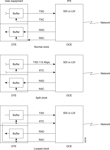
In the split clock mode, the IPX data interface card sends RxD synchronized to RxC to the DTE and receives both TxC and TxD synchronized to the DTE. Since the clock is not synchronized to the IPX, it is referred to as an isochronous clocking. This timing is carried through the IPX network to the far end where it synchronizes the far end RxC and RxD. In this mode, the external equipment must use the clock output by the IPX to clock in the appropriate data stream (RxD for DCE, TxD for DTE).
In the looped clock mode, the IPX data interface card sends a receive clock (RxC) to the DTE along with the receive data. The DTE takes this RxC and uses it to time both receive data and transmit data. It also loops it back to the IPX as transmit clock (TxC) or external transmit clock (XTC) and expects to receive data synchronous with that clock. In this mode, the external equipment must synchronize to the clock output by the IPX and use that clock for its transmit data stream.
Isochronous clocking is implied by "DTE—normal" "DCE—split" and "DTE—split" modes (although the clock mode at the other end of the connection must be compatible). Isochronous connections are buffered at the receive end for an additional 10 msec to allow for clock fluctuations, and automatically use a 20/sec EIA update rate to maintain accuracy.
The clock types may be set differently at each end of a data circuit with some care in selecting the options. The restrictions to keep in mind are:
If both ends of the data circuit are set for DTE normal, indicating the external device is supplying timing to the IPXs at both ends, a source of external timing for synchronization is required. The IPX cannot synchronize a different source of clocking at different ends of the connection unless they are both synchronized to the same master clock. If the external equipment is not synchronized to a common clock, buffer over-flows and under-flows will result, and data will be lost.
![]()
![]()
![]()
![]()
![]()
![]()
![]()
![]()
Posted: Thu Jan 18 12:52:40 PST 2001
All contents are Copyright © 1992--2001 Cisco Systems, Inc. All rights reserved.
Important Notices and Privacy Statement.