|
|

This chapter describes the FastPAD base unit. It includes a description of base unit models, front panel components, and the interior of the FastPAD.
The front panels for the FastPAD and FastPAD Micro are shown in Figure 2-1 and Figure 2-2. Either unit may be used on a desktop or mounted in a rack.
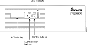
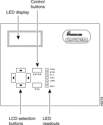
The base unit front panel for both models includes the following:
| LED | Description |
TRK | Composite link active signal |
SYN | Composite link synchronization |
FLT | Fault Condition |
TST | Self Test Mode |
LBK | Loop back Mode |
PS2 | Redundant Power Supply |
PS1 | Primary Power Supply |
The following paragraphs further describe the indications of the seven base unit front panel LEDs:
This LED shows the status of DCD (CI for V.11) provided to the composite trunk. If this LED is OFF, it indicates the communications device (e.g., modem) has lost carrier or is not physically connected to the FastPAD. | |
SYN: | This LED should be ON during normal operation. This LED will blink when the FastPAD has not established communications with an IPX or remote FastPAD. |
FLT: | This LED should be OFF during normal operation. When this LED blinks, it indicates a system malfunction. |
TST: | (not operational in the FastPAD). This LED should be OFF during normal operation. When this LED blinks, it indicates that one or more input channels (voice or data) and/or the composite link are in a loop back test mode. |
LBK: | This LED should be OFF during normal operation. When this LED blinks, it indicates the system has detected a loopback on the composite link circuit and is operating in loop mode. All data and voice channels are effectively looped back. The composite loop back mode can be selected from the Test menu (see Part II) or activated by a composite link loop back plug. |
PS1: | This LED should be ON during normal operation. When this LED is OFF, it indicates the primary power supply is malfunctioning. Contact StrataCom Customer Service (ISC) immediately: 800-767-4479 (US) and 1-408-947-6115 (International) |
PS2: | This LED will only be ON if a secondary power supply is installed. Otherwise, it should always be OFF. |
There are five RS-232 data ports, one high speed data port, one composite port, and one RS-232 asynchronous Network Management System (NMS) port on the back of the FastPAD. An IEC receptacle provides the connection to the AC power source via an AC power cord, as shown in Figure 2-3 and Figure 2-4
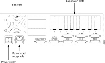
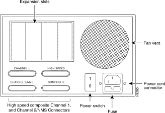
AC power modules have a fuse below the power connector. When replacing the fuse, make sure to use the exact type and rating marked next to the fuse holder. Fan vents located above the on/off power switch are for cooling and must not be blocked. The slotted panels that are visible from the back allow access to the individual PTT/telco connectors of each plug-in card installed in the internal expansion slots.

If the -48V DC power supply is installed, the back panel will include a DC input terminal with a fuse located directly above it as shown in Figure 2-6.

There are two screws in the center of the DC input terminal (under the safety cover) that can be used to attach DC power to the unit. Facing the back of the unit, the left screw is the positive (+) terminal and the right screw is the negative (-) terminal. This information is silk-screened on the back of the unit.
When attaching a DC power source, observe polarity: attach the positive lead from the power source to the positive terminal (+) on the back of the FastPAD, attach the negative lead from the power source to the negative terminal (-) on the back of the FastPAD. The fuse assembly is located immediately above the DC input terminal. To remove the fuse, use a flat-blade screw driver and gently press in on the fuse holder and rotate counter-clockwise. When replacing the fuse, make sure to use the exact type and rating marked next to the fuse holder (i.e. Time Delay 6.3 Amp 250V Fuse).
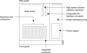
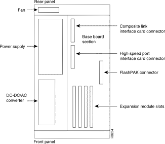
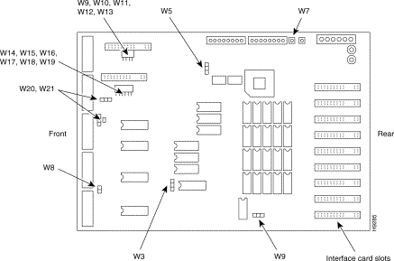
In general, the jumpers on the current base board are set at the factory for your particular installation requirements and need not be changed. If a base board is being upgraded, an upgrade kit will describe the jumpers that need to be set for a particular upgrade procedure.
 | Caution Do not change jumpers on the base board unless instructed to do so by StrataCom ISC. |
W3: This jumper selects 2K EEPROM or 8K EEPROM. In the 2-3 position, 8K EEPROM is selected. This is the normal position for a FastPAD.
W7: This jumper is normally OUT. When the jumper is IN, it connects AC ground to PTT ground. Jumper IN is not allowed in certain countries. Where it is allowed, it can be used as the "fifth" wire (ground connection) for four wire E&M connections.
W8: This jumper is reserved for future use. It should be IN for normal operation.
W9 (Next to U96): This jumper is set at 1-2 for a FastPAD.
W10, W11, W12, W13, W14, W15, W16, W17, W18, and W19: These jumpers are reserved for future use. Leave jumpers IN for normal operation.
W20 and W21: These jumpers are positioned at 1-2 for any interface on the high speed data channel except RS-449. The jumper is positioned at 2-3 when RS-449 is being used on the high speed data channel.
 | Warning Because of the presence of high voltages, the FastPAD must be unplugged from the AC power source before any attempt is made to remove the protective cover. |
FastPADs and FastPAD Micros include a universal AC power supply. In each case, the rear panel of the power supply will include a standard AC input plug with two fuses located directly below it. This power receptacle is a standard IEC 3-prong male power receptacle than can be used to provide AC input power to the unit. The fuse assembly is attached to the bottom of the power receptacle and contains two fuses. To remove the fuses, press down on the tab that extend out just below the power receptacle and between the two fuse holders. When replacing the fuses, make sure to use the exact type and rating marked next to the fuse holder (i.e., Time Delay 3.12 Amp 250V Fuse). A cooling fan is located at each end of the chassis next to the power supply and DC-DC/AC converter as shown in the following illustrations:
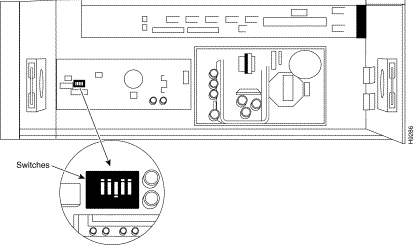
The DC Power Supply models accept DC input voltages in the range 42 to 60V DC. The AC Power Supply models accept standard AC input voltages in the range 90V to 240V AC and provides standard domestic/foreign line frequencies. The 5 position switch on the DC-DC/AC Converter selects a ring voltage and frequency as shown in the Table 2-2.
| Switch 1 | Switch 2 | Switch 3 | Ring Frequency Selected | Switch 4 | Switch 5 | Ring Voltage Selected |
|---|---|---|---|---|---|---|
Off/Closed | Off/Closed | Off/Closed | 17.5Hz | On/Open | On/Open | 81 VAC |
|
|
|
| On/Open | Off/Closed | 77 VAC |
On/Open | Off/Closed | Off/Closed | 20Hz | On/Open | On/Open | 80 VAC |
|
|
|
| On/Open | Off/Closed | 75 VAC |
Off/Closed | On/Open | Off/Closed | 25Hz | On/Open | On/Open | 75 VAC |
|
|
|
| On/Open | Off/Closed | 71 VAC |
Off/Closed | Off/Closed | On/Open | 50Hz | Off/Closed | Off/Closed | 70 VAC |
|
|
|
| Off/Closed | On/Open | 75 VAC |
If your hardware configuration does not match what you ordered or if you have any other questions, contact StrataCom International Support Center (ISC).
| English Test (UL/CSA) | German Test (VDE/TUV) | |
WARNING |
| WARNUNG |
Access to the interior of this unit shall be made only by a qualified technician. |
| Der Zugang ins Innere des Gerätes ist nur einem qualifizierten Techniker gestattet. |
1. To ensure adequate cooling of the equipment, a 2.0 inch unobstructed space must be provided around all sides of the unit. |
| 1. Um die Kühlung des Gerätes nich zu beeintrachtigen, ist es notwendig un das Gerätan allen Seiten ca 5 cm Raum zu lassen. |
2. The AC Power Socket shall be installed near the equipment and shall be easily accessible. |
| 2. Stellen sie das Gerät in der Nähe einer geerdeten Schutzkontaksteckdose so auf, daß diese leicht erreichbar und zuganglich ist. |
3. TECHNICAL DATA |
| 3. TECHNISCHE DATEN |
Input volts: 90-240V ~±10% |
| Nennspannung: 94-240V ~±10% |
Input Current: 0.92A-0.36A |
| Nennstrom: 0.92A-0.36A |
Frequency: 47-63 Hz |
| Frequenz: 47-63 Hz |
WARNING |
| WARNUNG |
Remove power plug from the power socket before performing any service work on the unit! |
| Vor öffnen Gerätes, muß der Netzstecker von dem Stomnetz gerennt werden! |
![]()
![]()
![]()
![]()
![]()
![]()
![]()
![]()
Posted: Thu Jan 25 13:29:58 PST 2001
All contents are Copyright © 1992--2001 Cisco Systems, Inc. All rights reserved.
Important Notices and Privacy Statement.