|
|

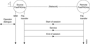
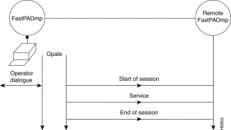
This function is used to identify the equipment and to transfer files. The following services are offered:
This function is accessible through:
1. An asynchronous terminal connected to the network, via the MMI function.

2. A management center workstation.
 Management Center Workstation
3. A personal computer, containing the OPALE software.
 a PC and OPALE Software
Certain services can be accessed only via a management center workstation or OPALE:
The following paragraphs describe the access to the MMI (Man Machine Interface) Function (asynchronous terminal).
In order to assure the file transfers this function uses a protocol of the transport type (OSI level 4). Therefore it is necessary to establish a session with the remote equipment.
The following menu is displayed:
TYPE COMMAND NUMBER

1	OPENING OF SESSION
2	RESERVED
3	END OF SESSION
4	END OF MMI
Code 1: | Set up of a simple session between two items of equipment and changeover to service level. |
Code 2: | Reserved. |
Code 3: | Return to welcome menu. |
Code 4: | End of communication with MMI function. |
The following series of menus is displayed:
CHOOSE REMOTE EQUIPMENT

1	 RESERVED
2 	RESERVED
3	 FastPADmp6, FastPADmp12, FastPADmpr

DNIC = | Data Network Identifier Code of "destination" equipment |
ZO = | Identification of "destination" of the equipment |
*AB = 99 = | Management function subscriber number |
FAC-VAL = | Facilities and values in accordance with ITU-T Recommendation X.25. |
09 = | Internal subscriber number for "destination" equipment software management function. |
PASSWORD = | Exists if it has been configured (TT by default). |
· without facilities: | 12340099,,09TT |
|
|
|
|
· with RC and CUG facilities: | 12340099, | 01-01, |
| 03-00 | ,09TT |
|
|
|
|
|
|
|
| RC |
| CUG |
|
* For the "hardware identification" function, the data are different for each module. To access this service on each module, it is necessary to select:
· AB = 90 = | Hardware identification of module 0. |
· AB = 91 = | Hardware identification of module 1. |
· AB = 92 = | Hardware identification of module 2. |
· AB = 99 = | Hardware identification of module on which the call was completed. |
TYPE COMMAND NUMBER

1	EQUIPMENT IDENTIFICATION
2	CONFIGURATION DOWNLOAD
3	RESERVED
4	CONFIGURATION UPLOAD
6	EQUIPMENT RESET
9	HARDWARE IDENTIFICATION
11	END OF SESSION
12	END OF MMI
This service indicates the identifiers of the Program and the Configuration files of the "destination" equipment.
FastPADmp MCX100-MCX200 PROGRAM
VERSION: 0001  RELEASE: 0000
EDITION: 0000
351125526451
CONFIGURATION
VERSION:      EDITION:
DATE: 20/04/94
USER:
This service makes it possible to download the contents of the configuration file from the "source" equipment to the "destination" equipment.
This service enables an operator to download a "compressed" operation software from OPALE or a management center workstation to equipment in operation.
The downloaded software is stored by the "destination" equipment in a RAM buffer.
Changeover to this software is obtained by means of the reset service.
This service makes it possible to upload the contents of the configuration file from the "destination" equipment to the "source" equipment.
This service allows the resetting of the "destination" equipment. The configuration to be taken into account during the start-up is indicated in the service request (by default, fixed or removable).
Resetting takes place on the "software" version stored in the buffer zone of the RAM or on the operational software version stored in Flash PROM.
1. Presence of a software version stored in RAM following on-line program downloading.
2. No software version stored in RAM:
The following menu is proposed:
1	ZONE MANUFACTURER
2	CUSTOMER
If code 1 is chosen:
PASSWORD
After the password has been entered, the following appears:
1	CONSULT EEPROM
2	MODIFY EEPROM
3	END OF HW IDENTIFICATION
This zone is reserved for the manufacturer. It describes the structure of the hardware and firmware equipment.
FLASH SIZE (10=1Mb, 0C=768kb, 8=512kb): 08
RAM SIZE (20=2Mb, 8=512kb): 20
EEPROM SIZE (40=256kb, 20=128kb, 10=64kb, 8=32kb): 08
NB OF LINES (0=6 lines, 3=12 lines): 00
TRANSPUTER (0=ABSENT, 1=PRESENT): 00
REF 255xxxxx OF THE MPB: 00000000
SERIAL NUMBER OF THE MPB: 0000
REF 255xxxxx OF THE MTB: 00000000
SERIAL NUMBER OF THE MTB: 0000
DELIVERY DATE: 00/00/00
FACTORY RETURN DATE: 00/00/00 00/00/00 00/00/00 00/00/00
TYPE OF CODING (0=BCD, 1=binary): 0
FLASH PROM SIZE (00): 20
LPB STATIC RAM SIZE (00=0kb, 01=64kb, 04=256kb): 00
TRANSPUTER STATIC RAM SIZE (01=128kb, 04=512kb): 00
TYPE OF MACHINE (00=CP100/200, 01=CL100/200): 00
ETHERNET ADDRESS: 0000 0000 00 00
PASSWORD
The default password is "IDENT"*.
After entering the password:
1	CONSULT EEPROM
2	MODIFY EEPROM
3	END OF HW IDENTIFICATION
then,
FIELD 1	8 characters
FIELD 2	8 characters
FIELD 3	8 characters
FIELD 4	8 characters
This zone is available for the customer.
Remark: The modifications to be carried out field by field.
* To modify the password:
After the selection of a service the following menu appears:
TYPE COMMAND NUMBER

1	EXECUTION
2	NO EXECUTION
During the execution of a service, two types of messages may be displayed:
These messages are described below:
COMMAND NOT AVAILABLE: | command recognized but not operational |
COMMAND ERROR: | command not recognized (e.g., syntax error) |
THE CALLER REFUSES | service rejected by "source" |
THE SERVICE: | FastPADmp equipment (to which the terminals connected) |
THE CALLED PARTY | service rejected by "destination" |
REFUSES THE SERVICE: | FastPADmp equipment, e.g., request for downloading of a configuration when configuration is already in progress. |
PROCESSING ERROR: | detection of an error during the execution of the service. |
INCORRECT EXECUTION: | incorrect execution of service |
CORRECT EXECUTION: | service correctly executed |
CALLING ADDRESS ERROR: | syntax error in address of "called" equipment |
FACILITY ERROR: | syntax error in facilities |
CONNECTION REFUSED: | application level of "source" or "destination" FastPADmp equipment rejects call set up |
BREAK OFF AT SESSION LEVEL: | call broken off by session level |
VC BROKEN OFF: | virtual circuit broken off by network protocol |
LEVEL 4 BREAK OFF: | call broken off by transmission level |
CALL DATA ERROR: | syntax error in call data. |
![]()
![]()
![]()
![]()
![]()
![]()
![]()
![]()
Posted: Thu Jan 25 13:49:56 PST 2001
All contents are Copyright © 1992--2001 Cisco Systems, Inc. All rights reserved.
Important Notices and Privacy Statement.