|
|

This management function executes hardware tests, even if the FastPADmp is still in operation.
It also allows connection/disconnection of switched lines in 108/2 mode.
These tests, designed to check the satisfactory working of the lines of the FastPADmp, are:
Each tested line will be out of order for the duration of the test.
It is not possible to perform more than one test at a time, and each test ends with a display of a report.
The available tests are as follows:
| Tested Element | Tests |
LINES | Connect1 Disconnect1 Error bit test:
Reading the interface status |
| 1Connection/Disconnection tests can be carried out on supervised lines only. No results are displayed via the outstanding events or the statistical functions. 2Diagram of loop backs L0, L2 and L3. |
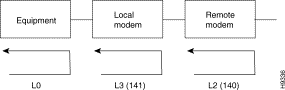
The modems (local and remote) have to support the loop commands in accordance with the CCITT V.54 recommendation (circuits CT140/141).
Loop L2 can be tested only when the remote modem manages circuit CT108.
The L0-loop can not be used in case of VIP and BSC.
When loop L0 is made, data is sent to the interface and, on a synchronous DTE line, clock signals are sent to the interface.
For the loops L2 and L3 on an asynchronous line, the FastPADmp responds only with "loop present" when the signals 142 and 106 are present.
The result of a connect/disconnect command on a switched line (PSTN/ISDN) is sent in the form of outstanding events; a report indicating the processing of the command is also distributed.
During a connection/disconnection, the behaviour of the PSTN/ISDN functions resulting from a call takes place on the caller side and on the called party side.
The syntax of these commands is given in the following paragraphs and the values and meanings of the outstanding events are given in Appendix A.
The access code syntax is the following:
IS No: | 11: BINARY MODE 12: ASCII MODE |
PASSWORD: | Exists if configured (MM is the default option). |
The validation of the access code to the Telemaintenance function results in the display of the following message:
COM |
The operator carries out the different tests using the specific commands described in the next paragraph.
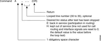
At the end of each test, a message is displayed within a time-out period of about 30 seconds.
Once the line is disconnected a status message is displayed (see the paragraph "contents of displayed messages").
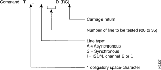
To reconnect the line, the operator must use the command T L---C described below.
The command is the same as for disconnection, but the character D (Disconnect) must be replaced by C (Connect).
T L---C(CR)
Once the line is connected, a status message is displayed (see the paragraph "contents of displayed messages").
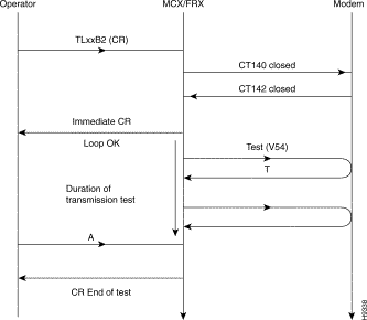
Procedure of the loop test:
 Flow
Flow
These loopback tests are carried out in two phases, with the display of an Intermediate Report and an End-of-test Report.
Loop back tests consist of:
The data consists of blocks of 64 byte (512 bits, according to the CCITT V.54 Recommendation).
Depending on the test command used, data blocks can be sent in two different ways:
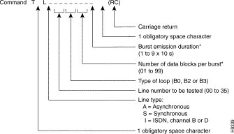
* If the fields "burst emission duration" and "Number of data blocks per burst" are empty, or when the entered values are not correct, data blocks are transmitted continuously till the operator transmits an end-of-test request.
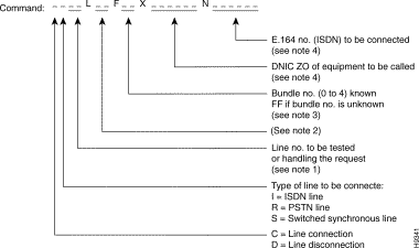 Connection/Disconnection Command Format
1. The number of the line to be tested is associated:
2. Only, ISDN disconnect order, to close a single B channel (L99).
3. The letter F indicates the addition of a line to a given MLP bundle. The bundle number is given after the letter F in two characters.
4. When it is preceded by the letter X, this number indicates the DNICZ0 of the equipment to be called.
5. When preceded by the letter P, this number indicates the number of the Permanent Logical Link to be connected/disconnected to the D channel of the specified S0 interface.
In the absence of a field in the command, it may be deduced, in the case of an MLP bundle, from classes 22 and 25 of the local configuration.
A PSTN line can offer only a single connection at a time and its use remains frozen. It is thus not possible to use it in a bundle or outside of a bundle (asynchronous or simple link, X.25). This is why, during a PSTN line disconnection, only the line number is handled; the other fields are ignored.
In the case of ISDN, the "X.121 number" and "E.164 number" fields are processed so as not to cut off the B channel(s) concerned.
The X.121 or ISDN numbers entered in the command have priority over those deduced from the configuration.
A PLL can be declared in a trunk.
During a connection in an MLP bundle, the DNICZO of the remote and the ISDN or PSTN number to be added are determined by the configuration.
In this case, the X.121-PSTN/ISDN conversion table allows the adoption of:
According to the test procedure, two types of reports can be transmitted by the telemaintenance function.
 End-of-test Report Command Formats
DISPLAYED | MEANING |
0000 0100 0200 0300 0400 0700 0701 0702
0500 0600 0800 0900 1220 1221 1222 2001 2040 4000
4100 | REPORT (FOR ALL SERVICES)
Test ended without error Unknown command Line number not correct Unknown line operation mode (synchronous or asynchronous) Unknown type of test Peripheral out of order Line of telemaintenance virtual circuit Line not monitored
REPORT FOR PERIPHERAL EQUIPMENT Test already in progress No test in progress Test in progress stopped Test impossible to stop (intermediate report in progress) Reception of at least one erroneous message At least one message sent, not received At least one message can not be sent No loop indicator (142) Test not available Loop (142) before time-out expired (synchronous mode) Loop (142) + presence of CT106 before time-out expired (synchronous mode) Loop B0 established |
DISPLAYED | MEANING |
3004
3006
3100
3400
3600
3700
3800
3900 | REPORT FOR MODEM MANAGEMENT
Session being opened
Modem stabilization period
Session opened
No reply from modem
No session opened
Session already opened
Modem data
Session opened without AT command
|
To obtain the "Interface status" service the following command has to be given:
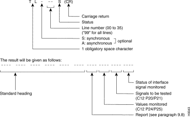
The meaning of the bits of each word are:
E/H = 0: | In service |
E/H = 1: | Not in service |
M/T = 0: | Terminal interface (T) => T |
M/T = 1: | Modem interface (M) => M |
On both lines the binary positions 4, 5, 6, 7 and 8 describe the outgoing signals configured.
The command T L 99S gives the status of all line interfaces. The result is given in the following form:
Every line is represented by 3 words with the following meaning:
List of specific status words characterizing the status of the lines (these status words are differentiated from a state of the signals by the positioning to 1 of bit 2 (bit 0 = LSB) corresponding to the mask 0008 H) :
· for an unconfigured line: | first word: | FFFF |
| second word: | FFFF |
| third word: | FFFF |
· for a line of a module in boot state: | third word: | F9F8 |
· for a line of a module in default configuration: | third word: | F9F9 |
· for a line of a module out of service: | third word: | F9FB |
· for a line of an inaccessi ble module: | third word: | F9FC |
· for a disconnected line: | third word: |
|
· F9FD for a modem interface |
|
|
· B9FD for a terminal interface |
|
|
The outstanding event of the family 04 generated following a disconnect contains this code as argument.
Only the X.25, asynchronous and ISDN (B-channel) lines in-service generate the OEV following a disconnect.
This service enables the management centre (or the asynchronous terminal) to access a modem (V.32, V.32bis, or V.32 FAST) of the network through FastPADmp equipment; the latter is transparent to the dialogue between the management centre and the modem.
It can NOT be requested for the line used to transfer the telemaintenance data via a VC of that line.
The telemaintenance command for modem management opens a session with the switching equipment which controls the modem. It identifies the modem by the connecting line number.
The command contains the Hayes prefix "AT". This confirms to the modem to go to the escape or the command mode.

* The "type Hayes modem command" is only used during the dialogue (with "DA").
When the session is opened (with "DO") the "type Hayes modem command" field is not used.
The result is displayed as follows:
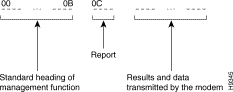
The packets received are translated into ASCII. The report packet can be accompanied by other packets (e.g. a carriage return packet or a packet in clear-language). It can be presented as follows:
![]()
![]()
![]()
![]()
![]()
![]()
![]()
![]()
Posted: Thu Jan 25 13:48:27 PST 2001
All contents are Copyright © 1992--2001 Cisco Systems, Inc. All rights reserved.
Important Notices and Privacy Statement.
