|
|

Table Of Contents
Preparing MPSM-T3E3-155 and MPSM-16-T1E1 Cards and Lines for Communication
Quickstart Provisioning Procedures
Preparing Cards and Lines for Configuration Quickstart
Moving MPSM Feature Licenses Quickstart
Channelizing DS3 (T3) Lines Configuration Quickstart
Channelizing Sonet Lines Configuration Quickstart
Channelizing SDH Lines Configuration Quickstart
General MPSM Provisioning Procedures
Selecting and Viewing Service Class Templates
Establishing Redundancy Between Two Lines with APS
Channelizing MPSM-T3E3-155 SONET, SDH, and DS3 (T3) Lines
Setting the Service Context on MPSM-T3E3-155 and MPSM-16-T1E1 Cards
Preparing MPSM-T3E3-155 and MPSM-16-T1E1 Cards and Lines for Communication
This chapter describes how to prepare MPSM-T3E3-155 and MPSM-16-T1E1 cards and lines for communications with other switches and customer premises equipment (CPE) by using the command-line interface (CLI).
These topics describe how to prepare MPSM-T3E3-155 and MPSM-16-T1E1 cards and lines for communication:
•
Quickstart Provisioning Procedures
•
Note
Preparing for Provisioning
Before you begin configuring lines and ports on MPSM-T3E3-155 and MPSM-16-T1E1 service modules, you need to initialize the cards you plan to provision. Then you should develop and implement a plan for the card and line redundancy options available for each service module. This plan determines how service modules and their back cards must be installed in the chassis, and how lines must connect to the cards before software configuration starts. Without a plan developed for these services, a configuration change for any of these services has the potential to interrupt service and can require substantial configuration teardown.
The MPSM-T3E3-155 card supports 1:1 card redundancy, and the MPSM-16-T1E1 card supports both 1:1 and 1:N card redundancy. The MPSM-T3E3-155 card supports both intercard and intracard APS.
The MPSM-T3E3-155 and MPSM-16-T1E1 service modules also require the management of feature licenses. The required feature licenses are described in "MPSM Feature Licenses".
For instructions on initializing cards, configuring card and line redundancy, and managing MPSM feature licenses on the PXM processor card, refer to the:
•
•
•
MPSM Feature Licenses
The MPSM-T3E3-155 and MPSM-16-T1E1 cards require feature licenses to enable the optional MPSM features listed in Table 2-1.
You must have the required license installed in the PXM license pool if you want to use any of the features described. To install and manage licenses on the PXM card, refer to the Cisco MGX 8800/8900 Series Configuration Guide, Release 5.2
For instructions on displaying, moving, and allocating feature licenses, and managing feature license alarms on the MPSM-T3E3-155 and MPSM-16-T1E1 cards, see "Managing Feature Licenses" in Chapter 6, "Card Management on MPSM-T3E3-155 and MPSM-16-T1E1."
Quickstart Provisioning Procedures
These quickstart procedures contain abbreviated procedures for preparing MPSM-T3E3-155 and MPSM-16-T1E1 cards and lines for communication:
•
•
•
•
•
These procedures are provided as an overview and as a quick reference for those who already have configured Cisco MGX switches.
Preparing Cards and Lines for Configuration Quickstart
This procedure describes how to prepare MPSM-T3E3-155 and MPSM-16-T1E1 cards for configuration:
Step 1
username
<password>
Start a configuration session with the active PXM card.
Note
Step 2
setrev
Related commands:
dspcds
From the active PXM card, initialize MPSM-T3E3-155 and MPSM-16-T1E1 cards by setting the firmware version level for each card.
Note
For instructions on initializing cards, refer to the Cisco MGX 8800/8900 Series Configuration Guide, Release 5.2.
Step 3
addred <options>
From the active PXM card, define which cards are operating as redundant cards.
Note
For instructions on adding card redundancy, refer to the Cisco MGX 8800/8900 Series Configuration Guide, Release 5.2.
Step 4
cc <options>
Change to an active MPSM-T3E3-155 or MPSM-16-T1E1 card from which you will select a card SCT.
Step 5
cnfcdsct <sctid>
Related commands:
dspcd
Apply ATM or Frame Relay communications parameters from a preconfigured Service Class Template (SCT) file to all communications between the card you are configuring and the other cards in the switch.
See the "Selecting and Viewing Service Class Templates" section, which appears later in this chapter.
Step 6
upln <bay.line>
Related commands:
dsplns
dspln -type <bay.line>
Bring up and configure lines. This step establishes physical layer connectivity between two switches.
See the "Setting Up Lines" section, which appears later in this chapter.
Step 7
cnfln <options>
Related commands:
dsplns
dspln <bay.line>
Configure lines.
To configure T1 lines, see the " Configuring DS1 (T1) Lines" section, which appears later in this chapter
To configure E1 lines, see the " Configuring E1 Lines" section, which appears later in this chapter
To configure T3 lines, see the " Configuring DS3 (T3) Lines" section, which appears later in this chapter.
To configure E3 lines, see the " Configuring E3 Lines" section, which appears later in this chapter.
To configure SONET/SDH lines, see the " Configuring SONET/SDH Lines" section, which appears later in this chapter.
Step 8
addapsln <workingIndex> <protectIndex> <archmode>
If you are using APS redundancy on the current card, configure a redundant relationship between two redundant lines.
Note
See the "Establishing Redundancy Between Two Lines with APS" section, which appears later in this chapter.
i
Moving MPSM Feature Licenses Quickstart
To move MPSM feature licenses from the MPSM-T3E3-155 and MPSM-16-T1E1 cards into the PXM license pool, perform the following steps:
Step 1
username
<password>
Start a configuration session.
Step 2
dspliccd
View the feature licenses that have been installed on the MPSM-T3E3-155 or MPSM-16-T1E1 card.
See the "Displaying Feature Licenses" section in Chapter 6, "Card Management on MPSM-T3E3-155 and MPSM-16-T1E1."
Step 3
movelic
Move the MPSM feature licenses programmed on the MPSM-T3E3-155 or MPSM-16-T1E1 card to the switch license pool on the PXM processor card.
See the "Moving MPSM Feature Licenses" section in Chapter 6, "Card Management on MPSM-T3E3-155 and MPSM-16-T1E1."
Step 4
dsplics
Related commands:
cnflic <options>
dspliccds
dspliccd <slot>
dsplicalmsNote
View the MPSM feature licenses installed in the PXM license pool.
See the "Displaying Feature Licenses" section in Chapter 6, "Card Management on MPSM-T3E3-155 and MPSM-16-T1E1."
Note
Note
Channelizing DS3 (T3) Lines Configuration Quickstart
Note
This procedure describes how to create channelized DS3 paths on the MPSM-T3E3-155 card:
Step 1
username
<password>
Start a configuration session with the active PXM card.
Note
Step 2
cc <options>
Change to an active MPSM-T3E3-155 card on which you will configure a path.
Step 3
upln
Bring up a line (bay.line).
See the "Setting Up Lines" section, which appears later in this chapter.
Step 4
cnfln <bay.line> -lt <LineType> -chan 2
Related commands:
dsplns
dspln -type <bay.line>
From the active card, configure the DS3 line with a valid line type for channelization, and enable channelization on the line.
See the "Configuring DS3 (T3) Lines" section, which appears later in this chapter.
Step 5
uppath [-pathfilter] <pathid>
Bring up the DS1 sub-paths that were created in Step 4.
See the " Bringing Up and Configuring DS1(T1) and E1 Paths" section, which appears later in this chapter.
Step 6
cnfpath <options>
Related commands:
dsppath
dsppathsConfigure the DS1 sub-paths.
See the " Bringing Up and Configuring DS1(T1) and E1 Paths" section, which appears later in this chapter.
i
Channelizing Sonet Lines Configuration Quickstart
Note
This procedure describes how to create channelized SONET paths on the MPSM-T3E3-155 card:
Step 1
username
<password>
Start a configuration session with the active PXM card.
Note
Step 2
cc <options>
Change to an active MPSM-T3E3-155 card on which you will configure a path.
Step 3
upln
Bring up a line (bay.line). When you bring up a line, the corresponding SONET path has a width of 3.
See the "Setting Up Lines" section, which appears later in this chapter.
Step 4
cnfpath -sts <pathid> -width <width spec>
Related commands:
dsppath
dsppathsFrom the active MPSM-T3E3-155 card, configure the SONET/SDH path width.
See the " Channelizing a SONET Line" section, which appears later in this chapter.
Step 5
uppath -sts <pathid>
Related commands:
dsppath
dsppathsBring up the SONET/SDH path.
See the " Bringing Up and Configuring SONET Paths" section, which appears later in this chapter.
Step 6
cnfpath -sts <pathid> -payload <sts_au_payload_type>
Related commands:
dsppath
dsppathsConfigure the payload type for the STS path you are channelizing.
See the " Bringing Up and Configuring SONET Paths" section, which appears later in this chapter.
Step 7
uppath [-pathfilter] <pathid>
Bring up the sub-paths that were created in Step 6.
To bring up DS3 paths, see the " Bringing Up and Configuring a DS3 (T3) Path" section, which appears later in this chapter
To bring up E3 paths, see the " Bringing Up and Configuring E3 Paths" section, which appears later in this chapter
To bring up DS1 paths, see the " Bringing Up and Configuring DS1(T1) and E1 Paths" section, which appears later in this chapter
Step 8
cnfpath <options>
Related commands:
dsppath
dsppathsConfigure the sub-paths.
To configure DS3 paths, see the " Bringing Up and Configuring a DS3 (T3) Path" section, which appears later in this chapter
To configure E3 paths, see the " Bringing Up and Configuring E3 Paths" section, which appears later in this chapter
To configure DS1 paths, see the " Bringing Up and Configuring DS1(T1) and E1 Paths" section, which appears later in this chapter
To configure TUG-3s, see the " Bringing Up and Configuring TUG-3s" section, which appears later in this chapter.
i
Channelizing SDH Lines Configuration Quickstart
Note
This procedure describes how to create channelized SDH paths on the MPSM-T3E3-155 card:
Step 1
username
<password>
Start a configuration session with the active PXM card.
Note
Step 2
cc <options>
Change to an active MPSM-T3E3-155 card on which you will configure a path.
Step 3
upln
Bring up a line (bay.line). When you bring up a line, the corresponding SDH path has a width of 3.
See the "Setting Up Lines" section, which appears later in this chapter.
Step 4
cnfln -<bay.line> -slt 2
-clk <clockSource>Configure the line you brought up in Step 3 to be an SDH line.
See the " Configuring SONET/SDH Lines" section, which appears later in this chapter.
Step 5
cnfpath -sts <pathid> -width <width spec>
Related commands:
dsppath
dsppathsFrom the active MPSM-T3E3-155 card, configure the SDH path width.
See the " Channelizing an SDH Line" section, which appears later in this chapter.
Step 6
uppath -sts <pathid>
Related commands:
dsppath
dsppathsBring up the SDH path.
See the " Bringing Up and Configuring SDH Paths" section, which appears later in this chapter.
Step 7
cnfpath -sts <pathid> -payload <sts_au_payload_type>
Related commands:
dsppath
dsppathsConfigure the payload type for the STS path you are channelizing.
See the " Bringing Up and Configuring SDH Paths" section, which appears later in this chapter.
Step 8
uppath [-pathfilter] <pathid>
Bring up the sub-paths that were created in Step 7.
To bring up DS3 paths, see the " Bringing Up and Configuring a DS3 (T3) Path" section, which appears later in this chapter
To bring up E3 paths, see the " Bringing Up and Configuring E3 Paths" section, which appears later in this chapter
To bring up DS1 paths, see the " Bringing Up and Configuring DS1(T1) and E1 Paths" section, which appears later in this chapter.
Step 9
cnfpath <options>
Related commands:
dsppath
dsppathsConfigure the sub-paths.
To configure DS3 paths, see the " Bringing Up and Configuring a DS3 (T3) Path" section, which appears later in this chapter
To configure E3 paths, see the " Bringing Up and Configuring E3 Paths" section, which appears later in this chapter
To configure DS1 paths, see the " Bringing Up and Configuring DS1(T1) and E1 Paths" section, which appears later in this chapter
To configure TUG-3s, see the " Bringing Up and Configuring TUG-3s" section, which appears later in this chapter.
i
General MPSM Provisioning Procedures
These topics and procedures describe preparing MPSM-T3E3-155 and MPSM-16-T1E1 cards for communication:
•
•
•
•
Selecting and Viewing Service Class Templates
These topics and procedures describe selecting and viewing Service Class Templates on the MPSM-T3E3-155 and MPSM-16-T1E1 cards:
•
•
Overview of Service Class Templates
A Service Class Template (SCT) is a file that contains default configuration data for switch connections and for configuring the hardware to support connections. When you configure a connection, or when an SVC is established, the switch analyzes the connection setup request data, any local configuration data, and the SCTs that apply to the port and to the card. For example, if an SPVC configuration does not include required data for the requested class of service (COS), default values from the SCT files are used. If an SVC request or SPVC configuration specifies configuration values that are different from the SCT values, the specified values override the default SCT values.
There are two types of SCTs: card SCTs and port SCTs. Card SCTs define configuration parameters for the hardware that transfers data between the a service module and the switch back plane. You can assign one card SCT to each service module.
Port SCTs define configuration parameters for the hardware that transfers data between a service module and a communication line to another switch or CPE. Port SCTs are assigned when a port is configured, and you can use different port SCTs on the same card, provided that the port SCT you select is designed for that card type.
Some SCT parameters control the service module hardware, and others are used as default values for connection parameters. A complete discussion of the SCT parameters is beyond the scope of this book.
SCT parameters are used to do the following:
•
•
•
•
•
SCTs simplify configuration by providing default values that will work for most connections. This reduces the number of parameters that need to be defined when setting up connections. Without SCTs, you need to perform a lot of detailed manual configuration on each and every port on the switch. This is time consuming and error prone. Typically, traffic profiles are defined by a handful of traffic engineering experts who understand the service level agreements and expected traffic pattern on the ports. These experts define the SCTs for each port in the system. Once the SCT is applied on the port, you do not need to (re)configure the switch. The parameters in the SCTs define generic thresholds and priorities of queues that can be understood without having to go through the programming details of Queuing engines, such as QE1210.
When configuring a service module card SCT, your goal should be to select the card SCT that will support the majority of planned connections on that card. When configuring a service module port SCT, your goal should be to select the port SCT that supports the majority of planned connections on that port.
Each service module contains default SCT parameters that you can use for communications. Cisco also supplies additional SCTs that you can use to better support communications. If none of the Cisco supplied SCTs meet your needs, you can use Cisco WAN Manager (CWM) to create your own custom SCTs. You can not create or modify SCT files using the CLI. For more information on configuring SCTs and SCT parameters, refer to the Cisco WAN Manager User's Guide, Release 15.1.
For information on downloading, registering, and managing SCTs on the PXM card, refer to the Cisco MGX 8800/8900 Series Configuration Guide, Release 5.2
MPSM Service Class Templates
SCT files are applicable to the MPSM-T3E3-155 and MPSM-16-T1E1 cards. Each SCT is classified by card or service module type, by whether it is a card or port SCT, and as either policing or non-policing. Although card SCTs may contain policing parameters, these parameters are ignored. Typically, policing SCTs are used on UNI ports at the edge of the ATM network and control traffic entering the network. Non-policing SCTs are typically on trunk ports that interconnect switches within the network.
Note
Table 2-2 lists the SCTs supplied by Cisco for the MPSM-T3E3-155 and MPSM-16-T1E1 cards. For the very latest information on Cisco SCTs, refer to the Release Notes for Cisco MGX 8850 (PXM1E/PXM45), Cisco MGX 8950, and Cisco MGX 8830 Switches, Release 5.2.00
Table 2-2 Cisco Provided SCTs for the MPSM-T3E3-155 and MPSM-16-T1E1
MPSM-T3E3-155
MPSM155_SCT.CARD.1.V1
Card
1
N/A
This is the only card SCT for this card.
MPSM155_SCT.PORT.1.V1
Port
1
On
Use for UNI ports greater than 4 T1 in bandwidth.
MPSM155_SCT.PORT.2.V1
2
Off
Use for NNI ports greater than 4 T1 in bandwidth.
MPSM155_SCT.PORT.3.V1
3
On
Use for UNI ports less than or equal to 4 T1 in bandwidth.
MPSM155_SCT.PORT.4.V1
4
Off
Use for NNI ports less than or equal to 4 T1 in bandwidth.
MPSM-16-T1E1
MPSM16T1E1_SCT.CARD.1.V1
Card
1
N/A
This is the only card SCT for this card.
MPSM16T1E1_SCT.PORT.3.V1
Port
3
On
Use for UNI ports less than or equal to 4 T1 in bandwidth. For UNI ports greater than 4 T1 in bandwidth, create a new custom SCT.
MPSM16T1E1_SCT.PORT.4.V1
Port
4
Off
Use for NNI ports less than or equal to 4 T1 in bandwidth. For NNI ports greater than 4 T1 in bandwidth, create a new custom SCT.
1 Cisco recommends using SCTs with policing enabled for UNI ports and using SCTs with policing disabled for NNI ports.
Note
Selecting a Card SCT
A card SCT defines the queue parameters for the destination slot based cell queues towards the backplane. The same card SCT may be used for multiple cards of the same card type.
When an MPSM-T3E3-155 or MPSM-16-T1E1 card is powered up for the first time, the default card SCT file is used. The default SCT file is 0.
Note
Selecting a Port SCT
A port SCT defines queue parameters that apply to egress queues on a port. You can use the same port SCT for multiple ports. Port SCTs can be changed with connections provisioned on the port. However, the port needs to be administratively down to effect this change. Hence this is service affecting.
Note
Setting Up Lines
The first step in configuring MPSM-T3E3-155 and MPSM-16-T1E1 lines is to bring up and configure the physical lines that are connected to the switch. These topics describe how to do the following tasks:
•
Bringing Up Lines
Installing an MPSM-T3E3-155 card can add from 1 to 3 lines to your switch. Installing an MPSM-16-T1E1 card can add from 1 to 16 lines. You must bring up a line before you can configure the line or provision services on the line.
Before a line is brought up, or after it is brought down, the switch does not monitor the line. The port status light for the line flashes green, and all line alarms are cleared. The flashing green light means the line is unprovisioned.
When you bring up a line, the switch starts monitoring the line. The port status light is green when physical layer communications are established with a remote switch. If physical layer communications problems are detected, the port status light turns red, and alarms are reported.
Note
Note
Tip
To bring up a line on the switch, use the following procedure.
Step 1
Step 2
M8850_NY.7.PXM.a > cc <slotnumber>Replace <slotnumber> with the number of the slot in which the card is installed. Valid slot numbers are as follows:
•
•
Verify your card selection by viewing the switch prompt, which should list the slot number and the card type.
Step 3
M8850_NY.13.MPSM155[ATM].a > upln <bay.line>Replace <bay> with 1, and replace <line> with the number that corresponds to the back card port to which the line is connected, as shown in the following example:
M8850_NY.13.MPSM155[ATM].a > upln 1.1
Note
Step 4
M8850_NY.13.MPSM155[ATM].a > dsplnsMedium MediumSonet Line Line Line Frame Line Line Valid Alarm APS Channe-Line State Type Lpbk Scramble Coding Type Intvls State Enabled lized------------- ----- ------------ ------ -------- ------ -------- ------ -------- ------- -------1.1 Up sonetSts3c NoLoop Enable NRZ ShortSMF 2 Clear Disable No1.2 Down sonetSts3c NoLoop Enable NRZ Other 0 Clear Disable NoThe line state column shows whether each line is up or down. The line state is the administrative intent for the line. For example, a line is reported as Down until an administrator brings up the line. Once the administrator brings up the line, the line state remains Up until the administrator brings the line down with the dnln command.
The alarm state indicates whether the line is communicating with a remote switch. When the alarm state is reported as Clear, the physical devices at each end of the line have established physical layer communications. ATM or Frame Relay connectivity is established later when interfaces or ports are configured on the line.
Configuring DS1 (T1) Lines
All line types are brought up with a default configuration. When configuring trunks between two Cisco MGX switches, you may be able to accept the defaults for each switch and thus minimize configuration time. When configuring a line to another type of device, ensure that both devices are using the same configuration parameters on the shared line.
The following procedure describes how to configure T1 lines.
Step 1
Step 2
M8850_NY.13.MPSM16[FR].a > dsplnsRemember that you cannot configure a line until you have brought it up as described in the previous section, "Bringing Up Lines".
Step 3
M8850_NY.13.MPSM16[FR].a > dspln 1.1For more information, see "Verifying Line Configuration", which appears later in this chapter.
Step 4
mpsm_node1.9.MPSM16T1E1[ATM] cnfln <bay.line> -lt<Line Type> -len<LineLength> -clk <clockSource> -lc <Line Coding>
Table 2-3 lists the parameter descriptions for configuring T1 lines.
Step 5
Configuring E1 Lines
All line types are brought up with a default configuration. When configuring trunks between two Cisco MGX switches, you may be able to accept the defaults for each switch and thus minimize configuration time. When configuring a line to another type of device, ensure that both devices are using the same configuration parameters on the shared line.
The following procedure describes how to configure E1 lines.
Step 1
Step 2
M8850_NY.13.MPSM16[FR].a > dsplnsRemember that you cannot configure a line until you have brought it up as described in the previous section, "Bringing Up Lines".
Step 3
M8850_NY.13.MPSM16[FR].a > dspln 1.1For more information, see "Verifying Line Configuration", which appears later in this chapter.
Step 4
mpsm_node1.9.MPSM16T1E1[ATM] cnfln <bay.line> -lt<Line Type> -clk <clockSource> -lc <Line Coding>
Table 2-4 lists the parameter descriptions for configuring E1 lines.
Step 5
Configuring DS3 (T3) Lines
All line types are brought up with a default configuration. When configuring trunks between two Cisco MGX switches, you may be able to accept the defaults for each switch and thus minimize configuration time. When configuring a line to another type of device, ensure that both devices are using the same configuration parameters on the shared line.
The following procedure describes how to configure T3 lines.
Step 1
Step 2
M8850_NY.13.MPSM16[FR].a > dsplnsRemember that you cannot configure a line until you have brought it up as described in the previous section, "Bringing Up Lines".
Step 3
M8850_NY.13.MPSM16[FR].a > dspln 1.1For more information, see "Verifying Line Configuration", which appears later in this chapter.
Step 4
M8850_NY.13.MPSM16[FR].a > cnfln <bay.line> -lt <LineType> -len <Length>
-oof <OOFCriteria> -cb <AIScBitsCheck> -rfeac <RcvFEACValidation> -sc <sendCode>
-clk <clockSource> -chan <channelization>
Table 2-5 lists the parameter descriptions for configuring T3 lines.
Step 5
Configuring E3 Lines
All line types are brought up with a default configuration. When configuring trunks between two Cisco MGX switches, you may be able to accept the defaults for each switch and thus minimize configuration time. When configuring a line to another type of device, ensure that both devices are using the same configuration parameters on the shared line.
The following procedure describes how to configure E3 lines.
Step 1
Step 2
Step 3
M8850_NY.13.MPSM155[ATM].a > dsplnRemember that you cannot configure a line until you have brought it up as described earlier in the " Bringing Up Lines" section.
Step 4
M8850_NY.13.MPSM155[ATM].a > cnfln <bay.line> -lt <lineType> -clk <clockSource> -txtrace
<TraceString>
Table 2-6 lists the parameter descriptions for configuring E3 lines.
Step 5
Configuring SONET/SDH Lines
All line types are brought up with a default configuration. When configuring trunks between two Cisco MGX switches, you may be able to accept the defaults for each switch and thus minimize configuration time. When configuring a line to another type of device, ensure that both devices are using the same configuration parameters on the shared line.
The following procedure describes how to configure SONET/SDH lines.
Step 1
Step 2
M8850_NY.13.MPSM155[ATM].a > dsplnsMedium MediumSonet Line Line Line Frame Line Line Valid Alarm APS Channe-Line State Type Lpbk Scramble Coding Type Intvls State Enabled lized------------- ----- ------------ ------ -------- ------ -------- ------ -------- ------- -------1.1 Up sonetSts3c NoLoop Enable NRZ ShortSMF 2 Clear Disable No1.2 Down sonetSts3c NoLoop Enable NRZ Other 0 Clear Disable NoRemember that you cannot configure a line until you have brought it up as described in the previous section, "Bringing Up Lines".
Step 3
M8850_NY.13.MPSM155[ATM].a > dspln 1.1Line Number : 1.1Admin Status : Up Alarm Status : ClearLoopback : NoLoop APS enabled : DisableFrame Scrambling : Enable Number of ATM ports : 0Xmt Clock source : localTiming Number of ATM partitions : 0Line Type : sonetSts3c Number of ATM SPVC : 0Medium Type(SONET/SDH) : SONET Number of ATM SPVP : 0Medium Time Elapsed : 823 Number of ATM SVC : 0Medium Valid Intervals : 2 Number of ATM Sig VC : 0Medium Line Type : ShortSMF Number of FR ports : 0Channelized : No Number of FR Connections : 0Num of STS-Paths/AUs : 1 Number of IMA Links : 0Provisioned Paths/AUs : 0For more information, see the "Verifying Line Configuration" section later in this chapter.
Step 4
M8850_NY.13.MPSM155[ATM].a > cnfln <bay.line> -slt <LineType> -clk <clockSource>Table 2-7 lists the parameter descriptions for configuring SONET/SDH lines.
Step 5
Verifying Line Configuration
To display the configuration of a line, use the following procedure.
Step 1
Step 2
M8850_NY.13.MPSM155[ATM].a > dsplnsStep 3
M8850_NY.13.MPSM155[ATM].a > dspln <bay.line>Replace bay with 1, and line with a number in the range from 1-3 on the MPSM-T3E3-155 or from 1-16 on the MPSM-16-T1E1.
Note
In the following example, the line configuration of a SONET line appears as follows:
M8850_NY.13.MPSM155[ATM].a > dspln 1.2Line Number : 1.2Admin Status : Down Alarm Status : ClearLoopback : NoLoop APS enabled : DisableFrame Scrambling : Enable Number of ATM ports : 0Xmt Clock source : localTiming Number of ATM partitions : 0Line Type : sonetSts3c Number of ATM SPVC : 0Medium Type(SONET/SDH) : SONET Number of ATM SPVP : 0Medium Time Elapsed : 0 Number of ATM SVC : 0Medium Valid Intervals : 0 Number of ATM Sig VC : 0Medium Line Type : Other Number of FR ports : 0Channelized : No Number of FR Connections : 0Num of STS-Paths/AUs : 0 Number of IMA Links : 0Provisioned Paths/AUs : 0M8850_NY.13.MPSM155[ATM].a >Establishing Redundancy Between Two Lines with APS
The Cisco MGX switch supports two types of line redundancy:
•
•
The MPSM-T3E3-155 card supports APS when using the SFP-2-155 or SMB-2-155-EL back cards. APS is not supported on the MPSM-16-T1E1 card.
These topics describe how to add redundancy for these types of APS lines:
•
•
Adding Intracard APS Lines on the Same Card
To establish redundancy between two lines on the same card, use the following procedure.
Step 1
Step 2
Step 3
M8850_NY.13.MPSM155[ATM].a > addapsln <workingIndex> <protectIndex> <archmode>Replace <workingIndex> with the location of the working line using the format "slot.bay.line." For example, to specify the line on card 2, line 2, enter 2.1.2.
Note
Replace <protectIndex> with the location of the protection line, using the same format used for the working line.
Note
Replace <archmode> with the option number that selects the automatic protection switching (APS) architecture mode (or protocol) you want to use. Table 2-8 shows the option numbers and the architecture modes they select, and whether that mode is revertive.
In the following example, 1+1 APS redundancy is assigned to two lines on the same card:
M8850_NY.13.MPSM155[ATM].a > addapsln 1.1.1 1.1.2 1Step 4
Step 5
Note
Adding Intercard APS Lines on Different Cards
To establish redundancy between two lines on different cards, use the following procedure.
Note
Step 1
Step 2
Step 3
Step 4
Step 5
M8850_NY.13.MPSM155[ATM].a > addapsln <workingIndex> <protectIndex> <archmode>Replace <workingIndex> with the location of the working line using the format slot.bay.line. For example, to specify the line on card 2, bay 1, line 2, enter 2.1.2.
Replace <protectIndex> with the location of the protection line, using the same format used for the working line.
Note
Replace <archmode> with an option number that defines the type of line redundancy you want to use. Table 2-9 shows the option numbers and the architecture modes (or protocols) they select, and whether that mode is revertive. Note that option 2 (1:1 signaling) is not available for Intercard APS.
In the following example, 1+1 APS redundancy is assigned to lines on two different cards:
M8850_NY.13.MPSM155[ATM].a > addapsln 1.1.2 2.1.2 1Step 6
Note
Step 7
Note
Channelizing MPSM-T3E3-155 SONET, SDH, and DS3 (T3) Lines
These topics and procedures describe channelization on the MPSM-T3E3-155 card:
•
•
•
•
•
•
•
•
Overview of Channelization on the MPSM-T3E3-155 Card
The MPSM-T3E3-155 supports clear channel services and channelized lines.
Note
If a line is not channelized, it is said to be a clear channel line, and the full bandwidth of that line is dedicated to a single channel or path that carries broadband services.
When a line is channelized, it is logically divided into smaller bandwidth channels called paths. These paths can carry an ATM or Frame Relay payload by themselves, or they can be channelized into smaller bandwidth paths that carry the ATM or Frame Relay payload. The sum of the bandwidth on all paths cannot exceed the line bandwidth. Channelized OC3 lines carry broadband and narrowband services, and channelized DS3 (T3) lines carry narrowband services only.
If you are already familiar with configuring Cisco MGX 8850 switches, you know that most cards provision services (such as ATM or Frame Relay) when assigning ports to a line. When a Synchronous Optical Network (SONET) or Synchronous Digital Hierarchy (SDH) line is channelized, these services are provisioned when assigning a port to a path. Channelized paths are simply a logical layer between the port and the line.
The channelization feature in this release allows the following types of channelization:
•
•
A SONET synchronous transport signal (STS) is an electrical signal that gets combined with other electrical signals before being transported over an optical line. An STS-3 path has the same bandwidth as an OC-3 line, but it is not labeled with the OC rating if it is merely a path within a higher bandwidth line. For example, you can configure up to 3 STS-1 width paths in an OC-3 line.
A synchronous transport module (STM) signal is the SDH equivalent of the SONET STS, but the numbers are different for each bandwidth. In this guide, the STM term refers to both path widths and optical line rates. The paths within an STM signals are called Administrative Units (AUs).
Channelizing a line is a two-step process:
•
•
Because paths support ATM and Frame Relay on different payloads, you need to specify which payload type will travel over each path, and you may want to configure additional options for each payload and path type. The sections that follow describe how to channelize lines, bring up paths, and configure paths.
When a line is brought up initially, there is one path with a width of 3. On a SONET line, a path width of 3 indicates that the line contains one clear channel STS-3 path. On an SDH line, a path width of 3 indicates that the line contains one clear channel STM-1/AU-4. To implement channelization, you need to set the path to the width 1. On SONET lines, a width of 3 results in one path only. On SDH lines, a width 3 path can be channelized into structured Virtual Tributaries (VTs).
MPSM-T3E3-155 Line Channelization
The channelization feature allows you to create a simple or complex combination of paths for each line on your MPSM-T3E3-155 back card. The simplest approach assigns the same bandwidth to each path. For an OC-3/STM-1 line, the simple approach is to configure 1 STS-3/STM-1 path.
A more complex approach creates different path widths within the same SONET/SDH/T3 line. Depending on the type of line being channelized and the channelization scheme used, different types of paths are created.
Table 2-10 lists the SONET, SDH, and T3 path types that are supported in Release 5 of the MPSM-T3E3-155 card.
Note
Table 2-11 shows the channel payloads that are supported by each interface type.
You can assign ATM service to any level path down to DS1, and you can assign Frame Relay service to any level path down to DS0. For example, an STS-1 path can be channelized into two individual DS1 paths, so that one DS1 path carries ATM service, and the other DS1 path carries DS0s with Frame Relay service.
Note
Keep the following in mind when configuring paths on a channelized line:
•
•
•
•
•
•
•
•
•
•
•
•
•
•
•
Channelization in SDH Networks versus SONET Networks
SONET networks and SDH networks use different terminology to describe the same elements in a channelized line. Table 2-13 lists the SONET terms and their equivalent SDH terms.
SONET path and interface numbering is different from SDH path and interface numbering. Table 2-14 defines the interface and path numbering for SONET and T3 lines, and Table 2-15 defines the interface and path numbering for SDH lines.
Table 2-14 Interface Numbering in SONET Networks
STS paths
bay.line.sts
DS3(T3)/E3 paths
bay.line.ds3
VT paths
bay.line.sts:vtg.vt
DS1(T1)/E1 paths
bay.line.sts:ds1
Table 2-15 Interface Numbering in SDH Networks
AU paths
bay.line.AU
DS3(T3)/E3 paths
bay.line.ds3
TU paths
bay.line.au:tug3.tu
DS1(T1)/E1 paths
bay.line.au:tug3.ds1
Note
Note
Tip
VTG and TUG-3 Configuration Elements
When OC3/STM-1 lines are channelized to carry tributaries, the tributaries are grouped together in a logical entity called a tributary group. In SONET networks, the tributary groups are called virtual tributary groups (VTGs). In SDH networks, the tributary groups are called Tributary Unit Groups (TUGs). Each individual VTG or TUG is a manageable path with a defined rate and format.
Note
In SONET networks, a single STS-1 line carries 7 separate VTGs. Each individual VTG can be configured independently from the other VTGs in that same STS-1, and can carry VTs of any size.
In SDH networks, a single STM-1 (AU-4) line carries 3 separate TUG-3s. Each individual TUG can be configured independently from the other TUGs in that same STM-0, and can carry TUs of any size.
Table 2-16 summarizes the elements tributary group configuration.
Note
Channelized Line Examples
The sections that follow provide examples of channelized DS3, SONET, and SDH lines.
Note
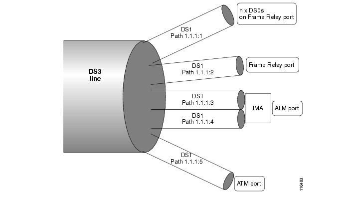
Example of a Channelized DS3 line
Figure 2-1 shows one possible way to channelize a DS3 line down to DS1 paths. In this example, the DS3 is mapped into 3 AU-3 (STM-0) paths. The paths are mapped as follows:
•
Note
•
•
•
•
Figure 2-1 Example of a Channelized DS3 line.
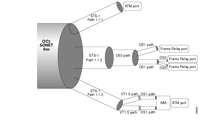
Example of a Channelized OC3 SONET line
Figure 2-2 shows one possible way to channelize a OC3 line down to DS0. In this example, the OC3 is channelize into 3 STS-1 paths. The paths are mapped as follows:
•
•
•
•
Note
Figure 2-2 Example of a Channelized SONET.
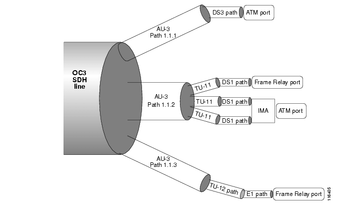
Example of a Channelized OC3 SDH line
Figure 2-3 shows one possible way to channelize a OC3 line down to DS1 paths. In this example, the OC3 is channelize into 3 AU-3 (STM-0) paths. The paths are mapped as follows:
•
•
•
•
Note
Figure 2-3 Example of a Channelized SDH OC3 line
Channelizing a DS3 Line
When a DS3 line is in clear channel mode, it carries a single DS3 path. You can channelize the DS3 line so that it contains three separate DS1 paths.
Note
Use the following procedure to channelize a DS3 line into twenty-eight DS1 paths.
Step 1
Step 2
Step 3
Step 4
M8830_CH.12.MPSM155[ATM].a > dsplnsLine Line Line Line Length OOF AIS Valid AlarmNum State Type Lpbk (meters) Criteria cBitsCheck Intvls State---- ----- --------------- ---------- -------- ----------- ---------- ------ ----------1.1 Up dsx3CbitParity NoLoop 0 3Of16Bits Check 96 Clear1.2 Up dsx3CbitParity NoLoop 0 3Of16Bits Check 25 Clear1.3 Down dsx3CbitParity NoLoop 0 3Of16Bits Check 0 ClearStep 5
Note
Note
In the following example, the user configures line 1.2 with the line type dsx3CbitParity.
M8830_CH.12.MPSM155[ATM].a > cnfln 1.2 -lt 11 -chan 2Step 6
In the following example, the user enters the dsppaths -all command to display all paths on the current card.
M8830_CH.12.MPSM155[ATM].a > dsppaths -allPath Path Admin DS1 Path Alarm Oper PathType Status Type Lpbk Status State Service----------- ----- -------- ----------- -------- -------- -------- ------------1.2:1 ds1 Down dsx1ESF NoLoop Unknown Down invalid1.2:2 ds1 Down dsx1ESF NoLoop Unknown Down invalid1.2:3 ds1 Down dsx1ESF NoLoop Unknown Down invalid1.2:4 ds1 Down dsx1ESF NoLoop Unknown Down invalid1.2:5 ds1 Down dsx1ESF NoLoop Unknown Down invalid1.2:6 ds1 Down dsx1ESF NoLoop Unknown Down invalid1.2:7 ds1 Down dsx1ESF NoLoop Unknown Down invalid1.2:8 ds1 Down dsx1ESF NoLoop Unknown Down invalid1.2:9 ds1 Down dsx1ESF NoLoop Unknown Down invalid1.2:10 ds1 Down dsx1ESF NoLoop Unknown Down invalid1.2:11 ds1 Down dsx1ESF NoLoop Unknown Down invalid1.2:12 ds1 Down dsx1ESF NoLoop Unknown Down invalid1.2:13 ds1 Down dsx1ESF NoLoop Unknown Down invalid1.2:14 ds1 Down dsx1ESF NoLoop Unknown Down invalid1.2:15 ds1 Down dsx1ESF NoLoop Unknown Down invalid1.2:16 ds1 Down dsx1ESF NoLoop Unknown Down invalid1.2:17 ds1 Down dsx1ESF NoLoop Unknown Down invalid1.2:18 ds1 Down dsx1ESF NoLoop Unknown Down invalidType <CR> to continue, Q<CR> to stop:Path Path Admin DS1 Path Alarm Oper PathType Status Type Lpbk Status State Service----------- ----- -------- ----------- -------- -------- -------- ------------1.2:19 ds1 Down dsx1ESF NoLoop Unknown Down invalid1.2:20 ds1 Down dsx1ESF NoLoop Unknown Down invalid1.2:21 ds1 Down dsx1ESF NoLoop Unknown Down invalid1.2:22 ds1 Down dsx1ESF NoLoop Unknown Down invalid1.2:23 ds1 Down dsx1ESF NoLoop Unknown Down invalid1.2:24 ds1 Down dsx1ESF NoLoop Unknown Down invalid1.2:25 ds1 Down dsx1ESF NoLoop Unknown Down invalid1.2:26 ds1 Down dsx1ESF NoLoop Unknown Down invalid1.2:27 ds1 Down dsx1ESF NoLoop Unknown Down invalid1.2:28 ds1 Down dsx1ESF NoLoop Unknown Down invalidStep 7
Channelizing a SONET Line
When a SONET line is in clear channel mode, it carries a single STS-3 path. You can channelize the SONET line so that it contains three separate STS-1 paths.
Use the following procedure to channelize a SONET line into three STS-1 paths.
Step 1
Step 2
Step 3
Step 4
Step 5
M8850_NY.13.MPSM155[ATM].a > cnfpath -sts <path_id> -width 1Replace the path_id variable with the complete path number in the format bay.line.sts, as shown in Table 2-12.
Note
-width <width_spec> parameter, see Table 2-12.The following example channelizes line 1.1.1 into three individual STS-1 paths.
M8850_NY.13.MPSM155[ATM].a > cnfpath 1.1.1 -width 1Step 6
M8850_NY.13.MPSM155[ATM].a > dsppaths -stsPath Path Admin Path Path Alarm OperType Status Payload Width Status State-------- -------- -------- ------------- ------- --------- ------1.1.1 sts Down unequipped 1 Unknown Down1.1.2 sts Down unequipped 1 Unknown Down1.1.3 sts Down unequipped 1 Unknown DownM8850_NY.13.MPSM155[ATM].a >
Note
Note
Bringing Up and Configuring SONET Paths
After you split a SONET line into multiple paths, you are ready to bring up the individual paths. You must bring up the individual path or paths before you can assign a payload to that path and proceed with further channelization. Once you assign a payload to a path, the path is channelized into separate paths.
The following procedures describe how to bring up path and configure the path for one of the following payload types:
•
•
•
•
•
Use the following procedure to bring up and configure a SONET path.
Step 1
Step 2
Step 3
Step 4
Step 5
M8850_NY.13.MPSM155[ATM].a > uppath -sts 1.1.1Step 6
Note
The following example shows how to configure a path for a DS3 payload:
M8830_CH.12.MPSM155[ATM].a > cnfpath -sts 1.4.47 -payload 3Step 7
M8830_CH.12.MPSM155[ATM].a > dsppath 1.4.47Path Number : 1.4.47 Path Type : stsPayload : ds3 Width : 1Admin Status : Up Alarm Status : ClearPath Operational State : lowLayerDnNumber of ports : 0 Number of partitions: 0Number of SPVC : 0 Number of SPVP : 0Number of SVC : 0Xmt.Trace :When the path is up, the Admin Status row displays Up. The Payload row displays the payload type.
Step 8
•
•
•
•
Channelizing an SDH Line
When an SDH line is in clear channel mode, it carries a single AU-4 path. You can channelize the AU-4 path into three separate AU-3 paths.
Note
The following procedure describes how to channelize an SDH line into three separate STM-0/AU-3 paths.
Step 1
Step 2
Step 3
Step 4
M8850_NY.13.MPSM155[ATM].a > dsppaths -allPath Path Admin Path Path Alarm OperType Status Payload Width Status State-------- -------- -------- ------------- ------- --------- ------1.1.0 sts Down unequipped 3 Unknown DownShelf Database table empty.SonetVTsTableShelf Database table empty.Ds3PathsTableShelf Database table empty.Ds1PathsTableIf want to channelize the AU-4 path into three smaller AU-3 paths, proceed to Step 5. If you want to channelize the AU-4 path into clear channel DS3 or clear channel E3 paths, skip the rest of the steps in this section and follow the procedure in the "Bringing Up and Configuring SDH Paths" section that follows.
Step 5
M8850_NY.13.MPSM155[ATM].a > cnfpath -sts <path_id> -width 1Replace the path_id variable with the complete path number in the format bay.line.sts, as shown in Table 2-12. The correct path number for unchannelized SDH line 1 on an MPSM-T3E3-155 card is 1.1.0.
The MPSM-T3E3-155 card supports two path widths:
•
•
You must enter -width 1 (STS-1/STM-0) to channelize an SDH path into three separate AU-3 paths. For more information about the width_spec parameter, see Table 2-12.
When you channelize a clear channel line, the cnfpath command channelizes the entire line into paths equal to the path width you specify.
The following example channelizes line 1.1.1 into 3 AU-3 paths.
M8850_NY.13.MPSM155[ATM].a > cnfpath -sts 1.1.0 -width 1Step 6
M8850_NY.13.MPSM155[ATM].a > dsppaths -stsPath Path Admin Path Path Alarm OperType Status Payload Width Status State-------- -------- -------- ------------- ------- --------- ------1.1.1 sts Down unequipped 1 Unknown Down1.1.2 sts Down unequipped 1 Unknown Down1.1.3 sts Down unequipped 1 Unknown Down
Note
Note
Bringing Up and Configuring SDH Paths
After you split an SDH line into multiple paths, you are ready to bring up the individual paths. You must bring up the individual path or paths before you can assign a payload to that path and proceed with further channelization. Once you assign a payload to a path, the path is channelized into separate paths
SDH STM-0/AU-3 paths support following payload types:
•
•
•
•
SDH STM-1/AU-4 paths support following payload types:
•
•
•
•
•
Use the following procedure to bring up and configure a SDH path.
Step 1
Step 2
Step 3
Step 4
Step 5
M8850_NY.13.MPSM155[ATM].a > uppath -sts 1.1.1Step 6
Note
The following example shows how to configure a path for a DS3 payload:
M8830_CH.12.MPSM155[ATM].a > cnfpath -sts 1.4.47 -payload 3Step 7
M8830_CH.12.MPSM155[ATM].a > dsppath 1.4.47Path Number : 1.4.47 Path Type : stsPayload : ds3 Width : 1Admin Status : Up Alarm Status : ClearPath Operational State : lowLayerDnNumber of ports : 0 Number of partitions: 0Number of SPVC : 0 Number of SPVP : 0Number of SVC : 0Xmt.Trace :When the path is up, the Admin Status row displays Up. The Payload row displays the payload type, which is either DS3, E3, VT 1.5, VT 2.0, VT structured or unspecified.
Step 8
•
•
•
•
Bringing Up and Configuring a DS3 (T3) Path
The following procedure describes how to bring up, configure, and channelize a DS3 path into twenty-eight individual DS1 paths.
Note
Step 1
Step 2
Step 3
Step 4
Step 5
M8830_CH.12.MPSM155[ATM].a > uppath -ds3 <path_num>If you are configuring a physical DS3 (T3) line that is attached to a BNC-3-T3 back card, you do not need to bring the DS3 path up, and you can skip this step and move on to Step 4.
Step 6
cnfpath -ds3 <path_id>[-cb <AIScBitsCheck>] [-oof <OOF Criteria>] [-lt <Line Type>] [-clk <Clock Source>] [-feac <RcvFEAC>] [-lpb <Loopback>]-chan 2
Note
Note
In the example that follows, the user enables channelization on the DS3 line 1.1.1:
M8830_CH.12.MPSM155[ATM].a > cnfpath -ds3 1.1.1 -chan 2Step 7
Step 8
Bringing Up and Configuring E3 Paths
You must bring up an E3 path before you can provision services on that path.
Note
The following procedure describes how to bring up a path and configure an E3 path.
Step 1
Step 2
Step 3
Step 4
Note
Step 5
M8830_CH.12.MPSM155[ATM].a > uppath -e3 <path_num>Step 6
cnfpath -e3 <path_id> [-lt <Line Type>] [-clk <Clock Source>] [-lpb <Loopback>] [-txtrace <traceString>]
The cnfpath command parameters are described in Table 2-12.
Note
In the following example, the user configures the E3 path 1.1.2 so that it has the line type e3g832frmronly, a local clock source, and no loopback.
M8850_NY.13.MPSM155[ATM].a > cnfpath -e3 1.1.2 -lt 17 -clk 2 -lpb 1Step 7
M8830_CH.12.MPSM155[ATM].a > dsppath -e3 1.4.4Bringing Up and Configuring DS1(T1) and E1 Paths
You must bring up a DS1/E1 path before you can provision services on that path. The following procedure describes how to bring up a path and configure channelized DS1/E1 paths.
Step 1
Step 2
Step 3
Step 4
Note
Step 5
M8830_CH.12.MPSM155[ATM].a > uppath [-ds1|e1] <path_num>Step 6
cnfpath [-ds1|e1] <path_id> [-lpb <Loopback>] [-lt <Line Type>] [-clk <Clock Source>]
The cnfpath command parameters are described in Table 2-12.
Note
Note
In the following example, the user configures the DS1 path 1.1.1:1 so that it has local loopback enabled, a dsx1ESF line type, and a local clock source.
M8850_NY.13.MPSM155[ATM].a > cnfpath -ds1 1.1.1:1 -lpb 2 -lt 2 -clk 2Step 7
M8850_NY.13.MPSM155[ATM].a > dsppath -ds1 1.1.1:1Path Number : 1.1.1:1 Path Type : ds1Admin Status : Up Alarm Status : ClearOperational State : lowLayerDn Number of ATM ports : 0DS1 Line Type : dsx1ESF Number of ATM partitions : 0Loopback : Local Number of ATM SPVC : 0Xmt. Clock Source : localTiming Number of ATM SPVP : 0Path Service : unspecified Number of ATM SVC : 0Send Code : No Number of ATM Sig VC : 0DS0 inuse Bitmap : 0x0 Number of FR ports : 0Number of FR connections : 0Number of IMA Links : 0Bringing Up and Configuring TUG-3s
When you configure the payload for an SDH AU-4/STM-1 path, three TUG-3s are created. All three of these TUG-3s carry the same payload you assigned to the AU-4/STM-1 path, unless you assigned a VT-structured payload to the AU-4/STM-1 path. In the case of VT-structured paths, the three TUG-3s have unspecified payloads. you can assign any payload to the TUG-3s, and each TUG-3 can carry a different payload.
Note
Use the following procedure to assign a payload to a TUG-3.
Step 1
Step 2
Step 3
M8850_NY.13.MPSM155[FR].a > dsppaths -allPath Path Admin Path Path Alarm OperType Status Payload Width Status State-------- -------- -------- ------------- ------- --------- ------1.1.0 sts Down unequipped 3 Unknown DownShelf Database table empty.SonetVTsTableShelf Database table empty.Ds3PathsTableShelf Database table empty.Ds1PathsTableStep 4
M8850_NY.13.MPSM155[FR].a > uppath -sts 1.1.0Step 5
8850_NY.13.MPSM155[FR].a > cnfpath -sts 1.1.0 -payload 9Step 6
M8850_NY.13.MPSM155[FR].a > dsptug3sTug3Id payload---------- -----------1.1.0: 1 unspecified1.1.0: 2 unspecified1.1.0: 3 unspecifiedStep 7
In the following example, the user configures a TU-3/DS3 payload on TUG-3 1.1.0:1.
M8850_NY.13.MPSM155[FR].a > cnftug3 1.1.0:1 -payload 4Step 8
M8850_NY.13.MPSM155[FR].a > dsptug3cnf 1.1.0:1Path Number : 1.1.0Tug3 Id : 1 Payload Type : tu3ds3M8850_NY.13.MPSM155[FR].a >Step 9
M8850_NY.13.MPSM155[FR].a > dsppaths -allPath Path Admin Path Path Alarm OperType Status Payload Width Status State-------- -------- -------- ------------- ------- --------- ------1.1.0 sts Up vtStructured 3 Clear lowLayerDnPath Path Admin Path Alarm OperType Status Width Status State------------ ------- ---------- ---------- --------- ---------1.1.0:1 vt Down 5-tu3 Unknown DownPath Path Admin DS3 Path Alarm Oper PathType Status Type Lpbk Status State Service-------- ----- -------- --------------- -------- -------- --------- -----------1.1.0:1 ds3 Down dsx3CbitParity NoLoop Unknown Down invalidShelf Database table empty.Ds1PathsTableStep 10
•
•
•
Setting the Service Context on MPSM-T3E3-155 and MPSM-16-T1E1 Cards
The MPSM-T3E3-155 and MPSM-16-T1E1 cards support both ATM and Frame Relay services simultaneously. In order to support these individual services, each card maintains the following service contexts:
•
•
This service context information is stored as a part of the card configuration for that logical slot on the hard disk on the controller card. You can switch to either service (ATM of Frame Relay) at any time by entering the setctx command. You need to switch to the appropriate service each time you want to manage Frame Relay or ATM services.
You can change the default service context of the logical slot with the cnfclictx command. The default service context is the context that will be used when you first cc to the card. For example, if you are only using ATM on a card, it would be best to set the default context to ATM. However, if half of the ports are configured for ATM and the other half are configured for Frame Relay, the default context may not matter to you, and you can set it any way you want to.
Before you can provision Frame Relay or ATM services on the card, you must ensure that it is in the proper service context. Before you can provision ATM services as described in Chapter 3, "Provisioning ATM Services on MPSM-T3E3-155 and MPSM-16-T1E1," the card must be in the ATM service context. Before you can provision Frame Relay services as described in Chapter 4, "Provisioning Frame Relay Services on MPSM-T3E3-155 and MPSM-16-T1E1," the card must be in the Frame Relay service context.
Setting the Default Service Context
The default service context is the service that is available when you first cc to the card. For example, if the card's default service context is set to Frame Relay, then that card will always be in the Frame Relay service context when you first cc to the card. On other words, only the Frame Relay CLI will be available until you change to the ATM CLI context with the setctx atm command, or until you change the default service context to ATM with the cnfclictx atm command. Use the following procedure to set the default service context.
Step 1
M8850_NY.13.MPSM155[FR].a > dspclictxThis card's default service context is: FRStep 2
M8850_NY.13.MPSM155[FR].a > cnfclictx atmStep 3
M8850_NY.13.MPSM155[FR].a > dspclictxM8850_NY.13.MPSM155[FR].a > This card's default service context is: ATMNote that the command prompt does not change to reflect the default service context that was set with the cnfclictx command. In the example, the command prompt shows [FR] (Frame Relay), even though the user just set the default CLI context to be ATM. This is because the current CLI context for the card in slot 13 has been set to Frame Relay with the setctx command. The switch prompt will show [FR] (Frame Relay) until the user changes the CLI context to be ATM with the setctx command, or until the user logs out of the current session.
Switching from one CLI Context to Another
The current CLI context for the MPSM-T3E3-155 or MPSM-16-T1E1 is reflected in the switch prompt. If the current CLI context for the card is ATM, the switch prompt includes [ATM] with the card name, as shown in the following example:
M8830_CH.12.MPSM155[ATM].a >
If the current CLI context for the card is Frame Relay, the switch prompt includes [FR] with the card name, as shown in the following example:
M8830_CH.12.MPSM155[FR].a >
To switch from one CLI context to another, enter the setctx <service context> command. Replace <service context> with atm to set the current CLI context to be ATM, or replace it with fr to set the current CLI context to be Frame Relay.
In the following example, the user sets the CLI context to be Frame Relay.
M8850_NY.13.MPSM155[ATM].a > setctx frM8830_CH.12.MPSM155[FR].a >Note that the switch prompt reflects the CLI context change to Frame Relay. Only the commands specific to the Frame Relay service context are visible and available in that CLI session until the CLI context is changed to ATM with the setctx atm command, or until the user ends the current session (if the default CLI context was set to ATM with the cnfclictx atm command.)
![]()
![]()
![]()
![]()
![]()
![]()
![]()
![]()
Posted: Tue Oct 24 15:13:13 PDT 2006
All contents are Copyright © 1992--2006 Cisco Systems, Inc. All rights reserved.
Important Notices and Privacy Statement.