|
|

Table Of Contents
Provisioning ATM Services on MPSM-T3E3-155 and MPSM-16-T1E1
Quickstart Provisioning Procedures
ATM Trunk Configuration Quickstart
PNNI UNI Port Configuration Quickstart
SPVC and SPVP Configuration Quickstart
PNNI Virtual Trunk Configuration Quickstart
Cisco BPX PNNI Trunk Configuration Quickstart
AINI Link Configuration Quickstart
IISP Link Configuration Quickstart
Configuring Inverse Multiplexing over ATM
Partitioning Port Resources on the PNNI Controller
Selecting the Port Signaling Protocol
Provisioning and Managing SPVCs and SPVPs
Defining Destination Addresses for Static Links
Provisioning ATM Services on MPSM-T3E3-155 and MPSM-16-T1E1
This chapter describes how to provision ATM services on the MPSM-T3E3-155 and MPSM-16-T1E1 cards, and provides procedures for adding ATM ports and connections to the physical lines and paths. The types of links and connections presented in this chapter are listed in Table 3-1.
Note
Before you perform the procedures in this section, you must set up the MPSM-T3E3-155 and MPSM-16-T1E1 cards and lines from the PXM controller as described in Chapter 2, "Preparing MPSM-T3E3-155 and MPSM-16-T1E1 Cards and Lines for Communication." Make sure that you select the appropriate card SCT for the controller that you are using.
The MPSM-T3E3-155 and MPSM-16-T1E1supports ATM SPVCs, SPVPs, and SVCs to the following cards:
•
•
•
•
•
•
•
•
•
•
•
To perform the procedures in this section, you must start a CLI session on the appropriate MPSM-T3E3-155 and MPSM-16-T1E1 cards by logging in with the appropriate username and password. For detailed information about usernames, passwords, and logging into the CLI, refer to the Cisco MGX 8800/8900 Series Configuration Guide, Release 5.2.
Note
Quickstart Provisioning Procedures
This section presents abbreviated procedures that you can use to configure lines and provision connections. These procedures are for experienced users who already have experience configuring the MPSM-T3E3-155 and MPSM-16-T1E1 cards.
ATM Trunk Configuration Quickstart
ATM trunks connect the switch to other ATM switches in the core ATM network. The quickstart procedure in this section provides a summary of the tasks required to configure ATM trunks on Cisco MGX switches. This procedure is a quick reference for those who have previously configured these types of connections.
Note
Step 1
username
<password>
Start a configuration session.
To perform all of the steps in this quickstart procedure, you must log in as a user with Group1 privileges or higher.
Step 2
cc
Change to the MPSM-T3E3-155 or MPSM-16-T1E1 card.
Step 3
setctx atm
If the current CLI context is Frame Relay, use the setctx atm command to ensure you are using the ATM CLI.
Step 4
upln
Bring up lines as described in the Chapter 2, "Preparing MPSM-T3E3-155 and MPSM-16-T1E1 Cards and Lines for Communication."
Step 5
addport
or
addimagrp
addimalnk
addimaport
Related command:
dspports
Add and configure ATM ports. This step establishes ATM communication between two ATM devices.
Specify NNI for interswitch trunks.
For standard port configuration, see the "Adding ATM Ports" section.
To configure ATM communication over an IMA group, see the " Configuring Inverse Multiplexing over ATM" section later in this chapter.
Note
Step 6
cnfport
Related commands:
dspports
dspports
Use this optional step to make changes to the port created in the previous step.
For more information on modifying ports, see the " Adding ATM Ports" section later in this chapter.
Step 7
cnfpart
Related commands:
dspparts
dsppart
Configure trunk resources that are assigned to the PNNI controller. This step can assign all trunk bandwidth to one controller, or it can assign portions of the trunk bandwidth to each controller.
See the "Partitioning Port Resources on the PNNI Controller" section.
Note
Step 8
cc
Change to the PXM card.
Step 9
dnpnport
cnfpnportsig
uppnport
Related commands:
dsppnports
dsppnport
dsppnportsig
Define the signaling protocol used on the trunk. Specify pnni10 for PNNI trunks.
Step 10
Configure the other end of the link. If the other end of the link is connected to another MPSM-T3E3-155 or MPSM-16-T1E1 card, repeat Step 1 through Step 8.
If the other end of the link is on a different card type, refer the documentation for that card.
Step 11
cc
dsppnni-link
dsppnni-neighbor
When both ends of the link are configured, change to the active PXM card and verify the PNNI communication between the two ends of the connection. In the dsppnni-link report, there should be an entry for the port for which you are verifying communication. The Hello state reported should be twoWayInside, and the Remote node ID should display the remote node ATM address after the second colon.
See the " Verifying PNNI Trunk Communication" section in Chapter 6, "Card Management on MPSM-T3E3-155 and MPSM-16-T1E1."
Step 12
cc
Change back to the appropriate card.
Step 13
setctx atm
If the current CLI context is Frame Relay, use the setctx atm command to ensure you are using the ATM CLI.
Step 14
upilmi
cnfilmi
Related commands:
dspports
dspilmis
This step is optional. Configure and start ILMI on trunks where you want to support Cisco WAN Manager or use ILMI features.
See the "Configuring ILMI on a Port" section.
After you configure an MPSM-T3E3-155 or MPSM-16-T1E1 trunk, the trunk is ready to support SVCs. You can also create SPVCs and SPVPs between the CPE at each end of the trunk.
PNNI UNI Port Configuration Quickstart
ATM UNI ports connect the switch to ATM end devices, which serve as the boundary between the ATM network and other communication paths or networks. Typical end devices include ATM routers and multiservice concentrators. UNI signaling is used between the end system (CPE) and the PNNI network for requesting calls.
The quickstart procedure in this section provides a summary of the tasks required to configure UNI ports on Cisco MGX 8850 (PXM1E/PXM45) and Cisco MGX 8830 switches. This procedure is provided as an overview and as a quick reference for those who have previously configured UNI ports.
Step 1
username
<password>
Start a configuration session.
To perform all of the steps in this quickstart procedure, you must log in as a user with Group1 privileges or higher.
Step 2
cc
Change to the MPSM-T3E3-155 or MPSM-16-T1E1 card.
Step 3
upln
Bring up MPSM-T3E3-155 lines as described in the Chapter 2, "Preparing MPSM-T3E3-155 and MPSM-16-T1E1 Cards and Lines for Communication."
Step 4
setctx atm
If the current CLI context is Frame Relay, use the setctx atm command to ensure you are using the ATM CLI.
Step 5
addport
or
addimagrp
addimalnk
addimaport
Related command:
dspports
Add and configure ATM ports. This step establishes ATM communication between two ATM devices.
Specify UNI for interswitch trunks.
For standard port configuration, see the "Adding ATM Ports" section.
To configure ATM communication over an IMA group, see the " Configuring Inverse Multiplexing over ATM" section later in this chapter.
Note
Step 6
cnfport
Related commands:
dspports
dspports
Use this optional step if you need to make changes to the port created in the previous step.
For more information on modifying ports, see the " Adding ATM Ports" section later in this chapter.
Step 7
cnfpart
Related commands:
dspparts
dsppart
Configure the trunk resources that are assigned to the PNNI controller. This step can assign all of the trunk bandwidth to one controller, or it can assign portions of the trunk bandwidth to each controller.
See the "Partitioning Port Resources on the PNNI Controller" section.
Note
Step 8
cc
Change to the PXM card.
Step 9
dnpnport <portid>
Bring down the port so it can be configured. The next three steps require this step.
Step 10
cnfpnportsig
Related commands:
dsppnports
dsppnport
dsppnportsig
Define the signaling protocol used on the line.
Specify uni30, uni31, or uni40.
Step 11
cnfaddrreg
addaddr
Related commands:
dsppnports
dspatmaddr
deladdr
Configure static ATM addresses for ports that require them.
See the "Configuring ILMI on a Port" section.
Step 12
addprfx
Related commands:
cnfaddrreg
dspprfx
If dynamic addressing is to be used on a port, define an ATM address prefix that ILMI can use when assigning addresses.
Step 13
uppnport
Bring up port after configuration is complete.
Step 14
cc
Change back to the appropriate card.
Step 15
setctx atm
If the current CLI context is Frame Relay, use the setctx atm command to ensure you are using the ATM CLI.
Step 16
upilmi
cnfilmi
Related commands:
dspports
dspilmis
Configure and start ILMI on the port. This step is required for dynamic addressing and the ILMI automatic configuration feature. Otherwise, it is optional.
See the "Configuring ILMI on a Port" section.
SVC Configuration Quickstart
Switched virtual circuits (SVCs) are the solution for on-demand connections. They are set up as needed and torn down when no longer needed. To enable this dynamic activity, SVCs use signaling. End systems request connectivity to other end systems and, provided that the requested services are available, the connection is set up at the time of the request. When idle, an SVC is taken down to save network bandwidth.
Cisco MGX 8850 (PXM1E/PXM45) and Cisco MGX 8830 switches can use the PNNI protocol to determine how to set up SVCs through the network. Because the switch automatically sets up SVCs, you do not have to configure SVC routes. However, the switch must be configured correctly before it can set up SVCs. The following quickstart procedure summarizes the tasks required to enable SVC communication. With the exception of CPE configuration, all these tasks are described in this chapter.
Note
Step 1
Configure the trunks that link the switches through which the ATM end stations connect. Be sure to add the PNNI controller on each switch and select that controller when partitioning trunks.
Step 2
dsppnni-reachable-addr network
At the PXM, verify connectivity between the node pairs that will host SVCs.
See the " Verifying End-to-End PNNI Communications" section in Chapter 6, "Card Management on MPSM-T3E3-155 and MPSM-16-T1E1."
Step 3
Configure UNI ports for the ATM end stations at each end of the SVC, and assign either static or dynamic addressing to each line. Be sure to add the PNNI controller on each switch and select that controller when partitioning trunks.
Step 4
See the CPE documentation.
Configure CPE devices for communication with the switch through the UNI ports configured in the previous step.
Step 5
dsppncons
This optional step displays the SVC connections that are operating. Enter this command on the active PXM.
It is beyond the scope of this guide to describe how to configure each model of CPE to communicate with the switch. To complete this configuration, you must learn the capabilities of the CPE and the switch and define a set of communication parameters that are supported by both devices. For example, the Cisco MGX 8850 (PXM1E/PXM45) and Cisco MGX 8830 switches support UNI 3.1 communication, but if the CPE does not, you must select a signaling protocol (such as UNI 3.0) that is supported by both devices.
After all requirements are met for SVC connections, CPE devices can establish SVC connections to other CPE devices on the same switched network.
SPVC and SPVP Configuration Quickstart
Soft permanent virtual circuits (SPVC) and soft permanent virtual paths (SPVP) are full-time circuits and paths that Private Network-to-Network Interface (PNNI) can reroute to avoid failed communication links or to utilize links that offer better bandwidth. SPVPs support multiple virtual circuits, whereas SPVCs represent a single virtual circuit.
The quickstart procedure in this section provides a summary of the tasks required to configure SPVCs and SPVPs on Cisco MGX 8850 (PXM1E/PXM45) and Cisco MGX 8830 switches. This procedure is provided as an overview and as a quick reference for those who have previously configured these types of connections.
Step 1
See the " "ATM Trunk Configuration Quickstart" section.
Configure the trunks that link the switches through which the ATM end stations connect. Be sure to add the PNNI controller on each switch and select that controller when partitioning trunks.
Step 2
dsppnni-reachable-addr network
At the PXM, verify connectivity between the node pairs that will host SVCs.
See the " Verifying End-to-End PNNI Communications" section in Chapter 6, "Card Management on MPSM-T3E3-155 and MPSM-16-T1E1."
Step 3
Configure UNI ports for the ATM end stations at each end of the SVC, and assign either static or dynamic addressing to each line. Be sure to add the PNNI controller on each switch and select that controller when you partition trunks.
Step 4
cc
Change to the MPSM-T3E3-155 or MPSM-16-T1E1 card.
Step 5
setctx atm
If the current CLI context is Frame Relay, use the setctx atm command to ensure you are using the ATM CLI.
Step 6
addcon
Related commands:
dspchans
dspchan
If you are configuring a double-ended SPVC/SPVP, configure the slave side of the SPVC/SPVP.
If the slave side of the connection is on:
•
•
Note
Step 7
dspcon
Verify the configuration for the connection you added in Step 6.
Step 8
username
<password>
or
cc
If you are configuring an SPVC/SPVP between:
•
•
Step 9
addcon
Related commands:
dspcon
dspcons
Add and configure the master side of an SPVC/SPVP on the remote card.
If the master side of the connection is on:
•
•
Step 10
dsppncons
This optional step displays the SVC connections that are operating. Enter this command on the active PXM.
PNNI Virtual Trunk Configuration Quickstart
Virtual trunks are introduced and explained in the Cisco MGX 8800/8900 Series Configuration Guide, Release 5.2. Figure 3-1 illustrates how to configure a virtual trunk.
The Cisco MGX 8850 (PXM1E/PXM45) and Cisco MGX 8830 switches support:
•
•
Figure 3-1 shows a network topology that has two virtual trunks. At Private Switch A, both virtual trunks use the same line to connect to the core ATM network. Within the core ATM network, soft virtual permanent paths (SPVPs) provide direct communication paths between the core edge switches. Private Switch A has virtual trunks to Private Switches B and C and communicates with them as though they were directly connected.
Figure 3-1 Virtual Trunk Configuration
To configure end-to-end virtual trunks, perform the following tasks:
•
•
The following procedure summarizes the task of configuring virtual trunks and SPVPs.
Step 1
username
<password>
Start a configuration session.
To perform all of the steps in this quickstart procedure, you must log in as a user with Group1 privileges or higher.
Step 2
cc
Change to the MPSM-T3E3-155 or MPSM-16-T1E1 card.
Step 3
upln
Bring up lines as described in the Chapter 2, "Preparing MPSM-T3E3-155 and MPSM-16-T1E1 Cards and Lines for Communication."
Step 4
setctx atm
If the current CLI context is Frame Relay, use the setctx atm command to ensure you are using the ATM CLI.
Step 5
Add a channelized path:
cnfpath
uppath
Related commands:
dsppath
dsppaths
Add and configure a channelized path. Perform this step only if you are configuring a virtual trunk on an MPSM-T3E3-155 port. See the "Channelizing MPSM-T3E3-155 SONET, SDH, and DS3 (T3) Lines" section in Chapter 2, "Preparing MPSM-T3E3-155 and MPSM-16-T1E1 Cards and Lines for Communication," for details.
Step 6
addport
or
addimagrp
addimalnk
addimaport
Related commands:
dspports
dspimagrps
dspimalnks
Add the virtual trunk end ports at the private switches. Select interface type 3 for VNNI. See the "Adding ATM Ports" section.
Or if you are configuring IMA, add and configure IMA groups, then IMA links, then IMA ports. See the "Configuring Inverse Multiplexing over ATM" section.
Note
Step 7
cnfpart
Related commands:
dspparts
dsppart
Optional: Configure the trunk resources that are assigned to the PNNI controller. This step can assign all trunk bandwidth to one controller, or it can assign portions of the trunk bandwidth to each controller.
Note
Note
See the "Partitioning Port Resources on the PNNI Controller" section.
Step 8
cc
Change to the PXM card.
Step 9
dnpnport
cnfpnportsig
uppnport
Related commands:
dsppnports
dsppnport
dsppnportsig
Configure the virtual trunk signaling at the private switches. Select PNNI signaling by setting the -nniver option to pnni10.
Step 10
cc
Change back to the card.
Step 11
setctx atm
If the current CLI context is Frame Relay, use the setctx atm command to ensure that you are using the ATM CLI.
Step 12
addport
or
addimagrp
addimalnk
addimaport
Related commands:
dspports
dspimagrps
dspimalnks
Add and configure the virtual trunk end ports at each core edge node. Specify interface type 1 for UNI or 2 for NNI.
See the "Adding ATM Ports" section.
Step 13
cnfpart
Related commands:
dspparts
dsppart
Configure the virtual trunk partitions at each core edge node. Use a VPI range that includes all VPI numbers set for virtual trunks on this line at the private switch.
Note
See the "Partitioning Port Resources on the PNNI Controller" section.
Step 14
cc
Change to the PXM card.
Step 15
dnpnport
cnfpnportsig
uppnport
Related commands:
dsppnports
dsppnport
dsppnportsig
Configure the virtual trunk signaling at each core edge node. Select no trunk signaling by setting the -univer option (UNI ports) to none or the -nniver option (NNI ports) to none.
See the " Selecting the Port Signaling Protocol" section, which appears later in this chapter.
Step 16
cc
Change to the MPSM-T3E3-155 or MPSM-16-T1E1 card.
Step 17
setctx atm
If the current CLI context is Frame Relay, use the setctx atm command to ensure you are using the ATM CLI.
Step 18
addcon <options>
Related commands:
dspcon
dspcons
For each virtual trunk, configure an SPVP between the virtual trunk ports at each edge of the core network.
Step 19
cc
Change to the PXM card.
Step 20
dsppnni-reachable-addr network
Verify PNNI connectivity between the two nodes that will host the virtual trunk end points.
See the " Verifying End-to-End PNNI Communications" section in Chapter 6, "Card Management on MPSM-T3E3-155 and MPSM-16-T1E1."
Cisco BPX PNNI Trunk Configuration Quickstart
When the Cisco SES PNNI controller is attached to a Cisco BPX switch, the Cisco BPX switch can participate in a PNNI network with Cisco MGX 8850 (PXM1E/PXM45) or Cisco MGX 8830 switches. The connection between a Cisco MGX 8850 (PXM1E/PXM45) or Cisco MGX 8830 switch and a Cisco BPX switch is a trunk between an MPSM card in the Cisco MGX switch and a Cisco BXM card in the Cisco BPX switch. For instructions on configuring the BXM end of the trunk, refer to the Cisco SES product documentation. This section describes how to configure the MPSM end of the trunk.
The procedure for configuring the MPSM end of the trunk is similar to the general procedure for configuring MPSM trunks. The following procedure is customized for setting up Cisco BPX PNNI trunks.
Note
Caution
Step 1
username
<password>
Start a configuration session.
To perform all of the steps in this quickstart procedure, you must log in as a user with Group1 privileges or higher.
Step 2
upln
Bring up lines as described in the Chapter 2, "Preparing MPSM-T3E3-155 and MPSM-16-T1E1 Cards and Lines for Communication."
Step 3
cnfpath
Related commands:
dsppath
dsppaths
Add and configure a channelized path. Do this step only if you are configuring a virtual trunk on an MPSM-T3E3-155. See "Channelizing MPSM-T3E3-155 SONET, SDH, and DS3 (T3) Lines" in Chapter 2, "Preparing MPSM-T3E3-155 and MPSM-16-T1E1 Cards and Lines for Communication.".
Step 4
uppath
Related commands:
dsppath
dsppaths
Bring up the path you configured in Step 3.
Step 5
addport
Related command:
dspports
Add and configure ATM ports. This step establishes ATM communication between two ATM devices.
Specify NNI for interswitch trunks and VNNI for virtual trunks.
For ATM ports, see the "Adding ATM Ports" section.
For IMA ports, see the "Configuring Inverse Multiplexing over ATM" section.
Step 6
cnfpart
Related commands:
dspparts
dsppart
Optional: Configure the trunk resources that are assigned to the PNNI controller. This step can assign all trunk bandwidth to one controller, or it can assign portions of the trunk bandwidth to each controller.
Note
See the "Partitioning Port Resources on the PNNI Controller" section.
Step 7
cc
Change to the PXM card.
Step 8
dnpnport
cnfpnportsig
uppnport
Related commands:
dsppnports
dsppnport
dsppnportsig
Configure the signaling protocol used on the trunk to be pnni10. For example:
MGX8850.7.PXM.a > cnfpnportsig <portid> -nniver pnni10Step 9
cc
Change back to the MPSM-T3E3-155 or MPSM-16-T1E1 card.
Step 10
upilmi
cnfilmi
Related commands:
dspports
dspilmis
Configure and start ILMI on the trunk. ILMI is required on the BXM end of the trunk, so it must be enabled on the MPSM side too.
See the "Configuring ILMI on a Port" section.
Step 11
cc
Change to the PXM card.
Step 12
dsppnni-link
dsppnni-neighbor
After you have configured both ends of the link, verify the PNNI communication. In the dsppnni-link report, an entry for the port for which you are verifying communication should appear. The reported Hello state should be twoWayInside and the Remote node ID should display the remote node ATM address after the second colon.
See the " Verifying PNNI Trunk Communication" section in Chapter 6, "Card Management on MPSM-T3E3-155 and MPSM-16-T1E1."
After you configure a Cisco BPX PNNI trunk, the trunk is ready to support SVCs. You can also create SPVCs and SPVPs between CPE at each end of the trunk as described in the "Configuring the Master Side of SPVCs and SPVPs" section.
AINI Link Configuration Quickstart
The quickstart procedure in this section provides a summary of the tasks required to configure ATM Inter-Network Interface (AINI) links on Cisco MGX switches. This procedure is an overview and acts as a quick reference for those who have previously configured these types of connections.
Note
Step 1
username
<password>
Start a configuration session.
To perform all of the steps in this quickstart procedure, you must log in as a user with Group1 privileges or higher.
Step 2
upln
Bring up lines as described in the Chapter 2, "Preparing MPSM-T3E3-155 and MPSM-16-T1E1 Cards and Lines for Communication."
Step 3
cnfpath
Related commands:
dsppath
dsppaths
Add and configure a channelized path. Do this step only if you are configuring a virtual trunk on an MPSM-T3E3-155. See the " Channelizing MPSM-T3E3-155 SONET, SDH, and DS3 (T3) Lines" section in Chapter 2, "Preparing MPSM-T3E3-155 and MPSM-16-T1E1 Cards and Lines for Communication," for details.
Step 4
uppath
Related commands:
dsppath
dsppaths
Bring up the path you configured in Step 3.
Step 5
addport
Related command:
dspports
Add and configure ATM ports. This step establishes ATM communication between two ATM devices.
Specify NNI for interswitch trunks and VNNI for virtual trunks.
See the "Adding ATM Ports" section.
Step 6
cnfpart
Related commands:
dspparts
dsppart
Optional: Configure the trunk resources that are assigned to the PNNI controller. This step can assign all trunk bandwidth to one controller, or it can assign portions of the trunk bandwidth to each controller.
See the "Partitioning Port Resources on the PNNI Controller" section.
Note
Step 7
cc
Change to the PXM card.
Step 8
dnpnport
cnfpnportsig
uppnport
Related commands:
dsppnports
dsppnport
dsppnportsig
Configure the signaling protocol used on the trunk to be aini. For example:
MGX8850.7.PXM.a > cnfpnportsig <portid> -nniver ainiStep 9
cc
Change back to the MPSM-T3E3-155 or MPSM-16-T1E1 card.
Step 10
addaddr
Add destination addresses to each end of the trunk.
See the "Defining Destination Addresses for Static Links" section.
Step 11
addaddr
Add static addresses to destination ports. This step is required when addresses are not dynamically assigned to the CPE at the destination ports.
See the "Defining Destination Addresses for Static Links" section.
IISP Link Configuration Quickstart
The quickstart procedure in this section provides a summary of the tasks required to configure Interim Inter-Switch Protocol (IISP) links on Cisco MGX switches. This procedure is provided as an overview and as a quick reference for those who have previously configured these types of connections.
Note
Step 1
username
<password>
Start a configuration session.
To perform all of the steps in this quickstart procedure, you must log in as a user with Group1 privileges or higher.
Step 2
Bring up MPSM-T3E3-155 lines as described in the Chapter 2, "Preparing MPSM-T3E3-155 and MPSM-16-T1E1 Cards and Lines for Communication."
Step 3
cnfpath
Related commands:
dsppath
dsppaths
Add and configure a channelized path. Do this step only if you are configuring a virtual trunk on an MPSM-T3E3-155. See the " Channelizing MPSM-T3E3-155 SONET, SDH, and DS3 (T3) Lines" section in Chapter 2, "Preparing MPSM-T3E3-155 and MPSM-16-T1E1 Cards and Lines for Communication," for details.
Step 4
uppath
Related commands:
dsppath
dsppaths
Bring up the path you configured in Step 3.
Step 5
addport
Related command:
dspports
Add and configure ATM ports. This step establishes ATM communication between two ATM devices.
Specify NNI for interswitch trunks and VNNI for virtual trunks.
See the "Adding ATM Ports" section.
Step 6
cnfpart
Related commands:
dspparts
dsppart
Optional: Configure the trunk resources that are assigned to the PNNI controller. This step can assign all trunk bandwidth to one controller, or it can assign portions of the trunk bandwidth to each controller.
See the "Partitioning Port Resources on the PNNI Controller" section.
Note
Step 7
cc
Change to the PXM card.
Step 8
dnpnport
cnfpnportsig
uppnport
Related commands:
dsppnports
dsppnport
dsppnportsig
Configure the signaling protocol used on the trunk.to be either iisp30 or iisp31 for IISP trunks. For example:
MGX8850.7.PXM.a > cnfpnportsig <portid> -nniver iisp31Step 9
cc
Change back to the MPSM-T3E3-155 or MPSM-16-T1E1 card.
Step 10
addaddr
Add destination addresses to each end of the trunk.
See the " Defining Destination Addresses for Static Links" section later in this chapter.
Step 11
addaddr
Add static addresses to destination ports. This step is required when addresses are not dynamically assigned to the CPE at the destination ports.
See the " Defining Destination Addresses for Static Links" section later in this chapter.
ATM Configuration Concepts
This section describes the following MPSM-T3E3-155 and MPSM-16-T1E1 ATM configuration concepts and general procedures:
•
•
•
•
•
Most of the descriptions and procedures in this section use ATM service context commands. See Chapter 7, "Command Reference" for detailed descriptions of the MPSM-T3E3-155 and MPSM-16-T1E1 ATM service commands and parameters. Some of the procedures in this section use PXM commands and PNNI commands. Refer to the Cisco MGX 8800/8900 Series Command Reference, Release 5.2 for descriptions of the PXM and PNNI commands and parameters.
Refer to the following documentation for additional information regarding ATM provisioning:
•
•
•
•
Adding ATM Ports
On an MPSM-T3E3-155 or MPSM-16-T1E1 card, a logical port is also called a virtual interface and is represented by the ifNum variable. The MPSM cards can have the following types of interfaces:
•
•
•
•
•
•
Bringing up a line establishes minimal connectivity between two nodes. When you add an ATM port to a line or path, you enable ATM communication over the line.
Each line can support UNI, NNI, VNNI, EVNNI, or EVUNI ports. UNI ports are used for lines that connect to PBXs, ATM routers, and other ATM devices that connect to the core ATM network through the switch. NNI ports are used for trunks that connect to other core ATM network devices, such as another MGX 8850 switch. VNNI ports support virtual trunk connections between two ATM end stations. EVNNI and EVUNI are enhanced virtual trunks for network and user connections.
You must configure one ATM port for each line or path to enable ATM communication over that link.
When you add the ATM port to the line or path, you define the port type (UNI, VUNI, NNI, VNNI, EVNNI, or EVUNI).
Note
To add an ATM port to a path or line, use the following procedure.
Step 1
Step 2
To display a list of the lines and their numbers, enter the dsplns command:
MGX8850.10.MPSM-155[ATM].a > dsplns.If you adding a port to a path, enter the dsppaths -all command to display a list of all paths:
MGX8850.10.MPSM-155[ATM].a > dsppaths -allStep 3
M8850_NY.13.MPSM155[ATM].a > dspportsifNum Line/ Admin Oper Guaranteed Maximum sctID ifType VPI MINVPI MAXVPI IMAPath State State Rate Rate Cnf/InUse (VNNI, (EVUNI, (EVUNI, GRPVUNI) EVNNI) EVNNI)----- ----------- ----- ---------- ---------- -------- ----------- ------ ------ ------- ------- ---4 1.1.1 Up LowLayerDn 100 100 0/ 0 =Def NNI 0 0 0 N/AThis command displays the existing port numbers on the card in the ifNum (interface number) column. The interfaces listed can include UNI, NNI, VNNI, EVNNI, and EVUNI ports. When you add a port, you must specify a port number that is unique on the card. For example, if port number 2 is assigned to line 1.1 (bay 1, line 1), you cannot use port 2 on any other line on that MPSM-T3E3-155 card.
Step 4
M8850_NY.13.MPSM155[ATM].a > addport <ifNum> <path_num> <guaranteedRate> <maxRate> <sctID>
<ifType> [-vpi <vpi>] [-minvpi <minvpi>] [-maxvpi <maxvpi>]
Table 3-2 lists the parameters for configuring ATM ports.
The following sample command adds an UNI port to a line:
M8850_NY.13.MPSM155[ATM].a > addport 20 1.2:1 1000 1000 0 1Step 5
M8850_NY.13.MPSM155[ATM].a > dspportsThis command displays all configured ports on the card. Port numbers are listed in the ifNum (interface number) column. If you want to view information on a particular port, note the number of that port.
M8850_NY.13.MPSM155[ATM].a > dspportsifNum Line/ Admin Oper Guaranteed Maximum sctID ifType VPI MINVPI MAXVPI IMAPath State State Rate Rate Cnf/InUse (VNNI, (EVUNI, (EVUNI, GRPVUNI) EVNNI) EVNNI)----- ----------- ----- ---------- ---------- -------- ----------- ------ ------ ------- ------- ---10 N/A Up LowLayerDn 1000 1000 0/ 0 =Def NNI 0 0 0 111 N/A Up LowLayerDn 1000 1000 0/ 0 =Def NNI 0 0 0 220 1.2:1 Up LowLayerDn 1000 1000 0/ 0 =Def UNI 0 0 0 N/A21 1.2:2 Up LowLayerDn 3622 3622 0/ 0 =Def UNI 0 0 0 N/AStep 6
MGX8850.10.MPSM-155[ATM].a > dspport <ifNum>Replace <ifNum> with the number assigned to the port during configuration. The following example shows information for port 4.
M8850_NY.13.MPSM155[ATM].a > dspport 4Interface Number : 4Line/Path Number : 1.1.1 IMA Group Number : N/AAdmin State : Up Operational State : LowLayernGuaranteed bandwidth(cells/sec): 1000 Number of partitions : 1Maximum bandwidth(cells/sec) : 1000 Number of SPVC : 0ifType : NNI Number of SPVP : 0VPI number (VNNI, VUNI) : 0 Number of SVC : 0Number of Sig VC : 0MIN VPI (EVNNI, EVUNI) : 0 MAX VPI (EVNNI, EVUNI): 0SCT Id : 0 =DefF4 to F5 Conversion : Disabled
Tip
Configuring Inverse Multiplexing over ATM
Inverse Multiplexing over ATM (IMA) is a protocol that combines multiple T1 or E1 interfaces into one high-speed IMA interface, called an IMA group.
Note
The IMA feature has the following capabilities and restrictions:
•
•
•
•
•
IMA is also supported on the following Cisco MGX 8850 and Cisco MGX 8830 cards:
•
•
•
•
Note
Note
Note
Configuring IMA is a 3-step process:
1.
2.
3.
Note
Creating an IMA Group
To create an IMA group, use the following procedure:
Step 1
Step 2
M8830_CH.12.MPSM155[ATM].a > addimagrp <group> <version> <minLinks> <txImaId> <txFrameLen>
<txclkMode> <diffDelayMax>
Table 3-3 describes the parameters for the cnfimagrp command.
In the following example, the user creates IMA group 1 running IMA version 1.0. The minimum number of links required for this group to operate is 3. The transmit IMA ID is 255, the transmit frame length is 128, the transmit clock mode is CTC, and the maximum differential delay is 100.
M8830_CH.12.MPSM155[ATM].a > addimagrp 1 1 3 255 128 1 100Step 3
M8830_CH.12.MPSM155[ATM].a > cnfimagrp <-grp group> [-ver <version>] [-txm <minLinks>] [-txid <txImaId>] [-txfl <txFrameLen>] [-dd <diffDelayMax>] [-uptim groupUpTime] [-dntim <groupDownTime>] [-vfb <verFallback> [-mode <autoRestart>] [-rxid <rxImaIdExpected>] [-cm <txclkMode>]
Table 3-4 describes the parameters for the addimagrp command.
Step 4
M8830_CH.12.MPSM155[ATM].a > dspimagrpsIma Min Tx Rx Tx Diff NE-IMA FE-IMA IMAGrp Lnks Frm Frm Clk Delay State State VerLen Len Mode (ms)--------------------------------------------------------------------------------1 3 128 128 CTC 100 StartUp StartUp 1.0Adding an IMA Link to an IMA Group
After you have created and configured an IMA group, you can begin adding IMA links to the group.
To add an IMA link to an IMA group, perform the following steps:
Step 1
M8850_NY.13.MPSM155[ATM].a > dspimagrpsIma Min Tx Rx Tx Diff NE-IMA FE-IMA IMAGrp Lnks Frm Frm Clk Delay State State VerLen Len Mode (ms)--------------------------------------------------------------------------------1 1 128 128 CTC 150 StartUp StartUp 1.12 1 128 128 CTC 150 StartUp StartUp 1.1Step 2
•
•
Note
Step 3
M8830_CH.12.MPSM155[ATM].a > addimalnk <link> <group>Table 3-5 describes the parameters for the addimalnk command.
In the following example, the user adds the DS1 path 1.1.3:1.1 to IMA group 1.
M8850_NY.13.MPSM155[ATM].a > addimalnk 1.1.3:1.1 1Step 4
M8850_NY.13.MPSM155[ATM].a > cnfimalnk -lnk <link> [-uplif <lifUpTime>]
[-dnlif <lifDnTime>] [-uplods <lodsUpTime>] [-dnlods <lodsDnTime>]
Table 3-6 describes the parameters for the cnfimalnk command.
In the following example, the user configures link 1.1.3:1.1 so that it has an LIF uptime of 25,000 milliseconds, an LIF downtime of 1000 milliseconds, an LODS integration uptime of 25,000 milliseconds, and an LODS integration downtime of 1000 milliseconds.
M8850_NY.13.MPSM155[ATM].a > cnfimalnk -lnk 1.1.3:1.1 -uplif 25000 -dnlif 1000
-uplods 25000 -dnlods 1000
Step 5
In the following example, the user displays the IMA link 1.1.3:1.1.
M8850_NY.13.MPSM155[ATM].a > dspimalnk 1.1.3:1.1IMA Link Number : 1.1.3:1.1IMA Link Group Number : 1Link Rel Delay (msecs) : 0Link NE Tx State : Unusable-FailedLink NE Rx State : Not In GrpLink FE Tx State : Not In GrpLink FE Rx State : Not In GrpLink NE Rx Failure Status : Link FailLink FE Rx Failure Status : No FailureIMA Link Tx LID : 0IMA Link Rx LID : 255Link Rx Test Pattern : 255Link Test Procedure Status : DisabledLink LIF Integ UpTime : 25000Link LIF Integ DownTime : 1000Link LODS Integ UpTime : 25000Link LODS Integ DownTime : 1000Adding an IMA Port
After you configure an IMA group, you must add a port to the group.
To add an IMA port to a group, perform the following steps:
Step 1
Step 2
Step 3
M8850_NY.13.MPSM155[ATM].a > dspportsifNum Line/ Admin Oper Guaranteed Maximum sctID ifType VPI MINVPI MAXVPI IMAPath State State Rate Rate Cnf/InUse (VNNI, (EVUNI, (EVUNI, GRPVUNI) EVNNI) EVNNI)----- ----------- ----- ---------- ---------- -------- ----------- ------ ------ ------- ------- ---5 1.1.3:1.2 Up LowLayerDn 100 100 0/ 0 =Def NNI 0 0 0 N/A6 1.1.3:1.3 Up LowLayerDn 100 100 0/ 0 =Def NNI 0 0 0 N/A7 1.1.3:1.4 Up LowLayerDn 100 100 0/ 0 =Def NNI 0 0 0 N/AThis command displays all ports on the card in the ifNum (interface number) column. When you add a port, you must specify a port number that is unique on the card. For example, if port number 5 is assigned to path 1.1.3:1.2, you cannot use port 5 on any other line on that card.
Note
Step 4
mgx8830a.1.MPSM155[ATM].a > addimaport <ifNum> <group> <guaranteedRate> <maxRate> <sctID>
<ifType> [-vpi <vpi>] [-minvpi <minvpi>] [-maxvpi <maxvpi>]
Table 3-7 lists parameters for adding IMA ports.
In the following example, the user adds IMA port 8 to IMA group 1. The port operates as an NNI and uses the default SCT, with a guaranteed minimum and maximum bandwidth rate of 100 cps.
M8850_NY.13.MPSM155[ATM].a > addimaport 8 1 100 100 0 2Step 5
M8850_NY.13.MPSM155[ATM].a > dspportsifNum Line/ Admin Oper Guaranteed Maximum sctID ifType VPI MINVPI MAXVPI IMAPath State State Rate Rate Cnf/InUse (VNNI, (EVUNI, (EVUNI, GRPVUNI) EVNNI) EVNNI)----- ----------- ----- ---------- ---------- -------- ----------- ------ ------ ------- ------- ---5 1.1.3:1.2 Up LowLayerDn 100 100 0/ 0 =Def NNI 0 0 0 N/A6 1.1.3:1.3 Up LowLayerDn 100 100 0/ 0 =Def NNI 0 0 0 N/A7 1.1.3:1.4 Up LowLayerDn 100 100 0/ 0 =Def NNI 0 0 0 N/A8 N/A Up LowLayerDn 100 100 0/ 0 =Def NNI 0 0 0 1Partitioning Port Resources on the PNNI Controller
After you add a line or trunk port, you must define how the port resources are used by the PNNI controller. You can assign all resources to the PNNI controller, or you can assign some of the port resources to the PNNI controller, including:
•
•
•
•
Note
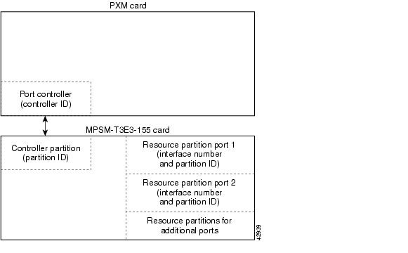
The port resources are defined as a group in a controller partition, which is dedicated to one port controller. You must define one controller partition for each controller type you want to support, and you must configure one resource partition for each port that uses a controller. Figure 3-2 presents a simplified view of the relationship between the port controller, controller partition, and resource partitions.
Figure 3-2 Relationship of Port Controller, Controller Partition, and Resource Partitions
Figure 3-2 shows that one controller partition connects to the port controller and to the resource partitions. When you add a port, a partition is automatically added. You can change the resource partition configuration using the cnfpart command.
To create additional resource partitions for a port, use the addpart command. It is important that the same controller partition, and therefore the same partition ID, be used for all resource partitions of the same type on the same MPSM-T3E3-155 card. For example, the controller is identified by the controller ID and the controller partition is identified by the partition ID. The resource partitions are identified by specifying the partition ID in combination with the port ID (interface number).
Important VPI/VCI Range Issues
When you configure a partition, be sure to configure the VPI/VCI ranges to meet your usage requirements. It is important that you do not configure the entire VPI/VCI range for one partition. The ability to seamlessly add new partitions in the future depends on configuring only the necessary ranges for each partition.
We recommend the following ranges for one partition:
•
•
To configure a resource partition for a port, use the following procedure.
Step 1
Note
Step 2
M8850_NY.13.MPSM155[ATM].a > dspportsifNum Line/ Admin Oper Guaranteed Maximum sctID ifType VPI MINVPI MAXVPI IMAPath State State Rate Rate Cnf/InUse (VNNI, (EVUNI, (EVUNI, GRPVUNI) EVNNI) EVNNI)----- ----------- ----- ---------- ---------- -------- ----------- ------ ------ ------- ------- ---10 N/A Up LowLayerDn 1000 1000 0/ 0 =Def NNI 0 0 0 111 N/A Up LowLayerDn 1000 1000 0/ 0 =Def NNI 0 0 0 220 1.2:1 Up LowLayerDn 1000 1000 0/ 0 =Def UNI 0 0 0 N/A21 1.2:2 Up LowLayerDn 3622 3622 0/ 0 =Def UNI 0 0 0 N/AThis command displays all ports on the card in the ifNum (interface number) column.
Step 3
M8850_NY.13.MPSM155[ATM].a > cnfpart -if <if> -id <partionID> -emin <egrMinBw>
-emax <egrMaxBw> -imin <ingMinBw> -imax <ingMaxBw> -vpmin <minVpi> -vpmax <maxVpi>
-vcmin <minVci> -vcmax <maxVci> -mincon <min connections> -maxcon <max connections>
Table 3-8 lists the parameters for configuring resource partitions.
Step 4
M8850_NY.13.MPSM155[ATM].a > dsppartsif part Ctlr egr egr ingr ingr min max min max min maxNum ID ID GuarBw MaxBw GuarBw MaxBw vpi vpi vci vci conn conn(.0001%)(.0001%)(.0001%)(.0001%)-----------------------------------------------------------------------------4 4 2 100000 100000 100000 100000 10 110 100 2000 100 500Step 5
M8850_NY.13.MPSM155[ATM].a > dsppart <ifNum> <partId>The following example shows the report provided by the dsppart command.
MGX8850.3.MPSM155[ATM].a > dsppart 4 4Interface Number : 4Partition Id : 4 Number of SPVC: 0Controller Id : 2 Number of SPVP: 0egr Guaranteed bw(.0001percent): 100000 Number of SVC : 0egr Maximum bw(.0001percent) : 100000ing Guaranteed bw(.0001percent): 100000ing Maximum bw(.0001percent) : 100000min vpi : 10max vpi : 110min vci : 100max vci : 2000guaranteed connections : 100maximum connections : 500
Selecting the Port Signaling Protocol
After you bring up a port, you need to set the signaling protocol to UNI or NNI. Use the following procedure to configure the port signaling protocol for a port.
Step 1
Step 2
MGX8850.7.PXM.a > dsppnportsStep 3
MGX8850.7.PXM.a > dnpnport <portid>A port is automatically brought up when you add it. Before you can change the port signaling protocol, you must bring down the port. Replace <portid> using the format slot[:bay].line[:ifNum].
Step 4
MGX8850.7.PXM.a > dsppnportsSummary of total connections(p2p=point to point,p2mp=point to multipoint,SpvcD=DAX spvc,SpvcR=Routed spvc)Type #Svcc: #Svpc: #SpvcD: #SpvpD: #SpvcR: #SpvpR: #Total:p2p: 0 0 0 0 0 0 0p2mp: 0 0 0 0 0 0 0Total=0Summary of total configured SPVC endpointsType #SpvcCfg: #SpvpCfg:p2p: 1 0p2mp: 0 0Per-port status summaryPortId IF status Admin status ILMI state #Conns7.35 up up Undefined 07.36 up up Undefined 07.37 up up Undefined 07.38 up up Undefined 0Type <CR> to continue, Q<CR> to stop:1:1.1:1 down down Disable 02:2.2:1 up up Disable 0Step 5
M8850_NY.7.PXM.a > cnfpnportsig <portid> [-univer {uni30|uni31|uni40|none|self}] [-nniver
{iisp30|iisp31|pnni10|enni|aini}] [-unitype {public|private}] [-addrplan {both|aesa|e164}]
[-side {user|network}] [-vpi <vpi>] [-sigvci <signalling-vci>] [-rccvci <routing-vci>]
[-cntlvc <ip>] [-passalongcap {enable|disable}][-hopcntgen {enable|disable}] [-vpivcialloc
{enable|disable}][-svcroutingpri <svcroutingPriority>]
The only required parameter for this command is the <portid> parameter, but the command serves no purpose if you do not enter at least one option with it. If you include some options with the command and omit others, the omitted option remains set to the last configured value.
Tip
Note
The following example illustrates how to configure an NNI port to use PNNI Version 1.0 signaling.
M8850_NY.7.PXM.a > cnfpnportsig 1:1.1:1 -nniver pnni10Step 6
M8850_NY.7.PXM.a > cnfoamsegep <portid>Replace <portid> using the format slot:bay.line:ifNum.
Note
Step 7
M8850_NY.7.PXM.a > uppnport <portid>Replace <portid> using the format slot:bay.line:ifNum.
Note
Step 8
Step 9
M8850_NY.7.PXM.a > dsppnport <portid>Replace <portid> using the format slot:bay.line:ifNum. The following example shows the report for this command.
M8850_NY.7.PXM.a > dsppnport 1:1.1:1Port: 1:1.1:1 Logical Id: 16848897IF status: up Admin Status: upUCSM: enableAuto-config: enable Addrs-reg: enableIF-side: network IF-type: nniUniType: private version: pnni10Input filter: 0 Output filter: 0minSvccVpi: 0 maxSvccVpi: 4095minSvccVci: 35 maxSvccVci: 65535minSvpcVpi: 1 maxSvpcVpi: 4095#SpvcCfg: #SpvcActive: #SpvpCfg: #SpvpActive:p2p : 0 0 0 0p2mp: 0 0 0 0#Svcc: #Svpc: Total:p2p : 0 0 0p2mp: 0 0 0Total : 0Configuring ILMI on a Port
Interim Local Management Interface (ILMI) is a feature you can activate on any ATM port. Activate ILMI on a port to perform any of the following tasks:
•
•
•
•
ILMI is enabled by default on all ports, but remains in a down state until ILMI is started.
To start ILMI on a port, you can either:
•
•
The sections that follow describe how to perform the following tasks:
•
•
•
•
Configuring ILMI Traps and Signaling
The default ILMI configuration uses standard ILMI signaling VPI and VCI, sets three ILMI signaling timers, and enables the distribution of ILMI management messages (traps) to SNMP managers such as CWM. If the defaults are acceptable, you can start ILMI on the port using the upilmi command. To change the defaults and start ILMI, use the following procedure.
Note
Step 1
Step 2
M8850_NY.13.MPSM155[ATM].a > dspilmisSig. rsrc Ilmi Sig Sig Ilmi S:Keepalive T:conPoll K:conPollPort Part State Vpi Vci Trap Interval Interval InactiveFactor---- ---- ---- ---- ---- --- ------------ ---------- ----------11 1 On 0 16 On 1 5 412 1 Off 0 16 On 1 5 413 1 Off 0 16 On 1 5 4The example above shows that ILMI is enabled on port 11 (ILMI State = On) and is disabled on ports 12 and 13 (ILMI State = Off). All other ILMI parameters are set to the default values.
Note
Step 3
MGX8850.10.MPSM-155[ATM].a > cnfilmi -if <ifNum> -id <partitionID> -ilmi <ilmiEnable>
-vpi <vpi> -vci <vci> -trap <ilmiTrapEnable> -s <keepAliveInt> -t <pollingIntervalT491>
-k <pollInctFact>
Table 3-9 lists the parameters for configuring resource partitions.
In the following example, the user enables ILMI on port 12.
M8830_CH.12.MPSM155[ATM].a > cnfilmi -if 12 -id 1 -ilmi 1Step 4
Configuring ILMI Automatic Configuration
Using the automatic configuration feature of ILMI Version 4.0, two devices that share a link can share their configurations and negotiate a common set of communication parameters. For example, if two network devices share a link and are configured for different maximum VCIs on a partition, the automatic configuration feature can determine and select the highest VCI supported by both nodes. To use ILMI automatic configuration, the devices at each end of the link must support the ILMI 4.0 feature.
Note
To enable or disable automatic configuration on a port, use the following procedure.
Step 1
Step 2
In the following example, the user displays the automatic configuration status of port 1 on the card in slot 12:
M8830_CH.1.PXM.a > dsppnport 12.5Port: 12.5 Logical ID: 17569797IF status: down Admin Status: upVSVD Internal Loop: unspecifiedVSVD External Loop: unspecifiedUCSM: enable SVC Routing Pri: 8Auto-config: enable Addrs-reg: enableIF-side: network IF-type: uniUniType: private Version: nonePassAlongCapab: n/aInput filter: 0 Output filter: 0minSvccVpi: 0 maxSvccVpi: 255minSvccVci: 35 maxSvccVci: 65535minSvpcVpi: 1 maxSvpcVpi: 4095P2P Details:(P=Configured Persistent Pep, NP=Non-Persistent Pep, Act=Active)#Spvc-P: #Spvc-NP: #SpvcAct: #Spvp-P: #Spvp-NP: #SpvpAct:1 0 0 0 0 0#Svcc: #Svpc: #Ctrl: Total:0 0 0 0P2MP Details:Type <CR> to continue, Q<CR> to stop:DSPPNPORT (P=Persistent, NP=Non-Persistent, Pa = Party, Act=Active)Type #Root: #Leaf: #Party:svcc: 0 0 0svpc: 0 0 0#Spvc-P: #Spvc-NP: #SpvcAct: #Spvp-P: #Spvp-NP: #SpvpAct:0 0 0 0 0 0#SpvcPa-P:#SpvcPaAct:#SpvpPa-P: #SpvpPaAct:0 0 0 0The Auto-config field shows whether the automatic configuration feature is enabled or disabled. In this example, automatic configuration is enabled.
Step 3
MGX8850.7.PXM.a > dnpnport 12.5Step 4
MGX8850.7.PXM.a > cnfautocnf <portid> <yes | no>Replace portid with the port address using the format slot.ifnum.
Enter yes to enable automatic configuration or enter no to disable automatic configuration.
Note
In the following example, the user disables the autoconfig feature on port 5 on the card in slot 12:
MGX8850.7.PXM.a > cnfautocnf 12.5 noStep 5
MGX8850.7.PXM.a > uppnport 12.5Step 6
Configuring ILMI Dynamic Addressing
Dynamic ATM addressing is enabled by default on all ports. After ILMI is started, ILMI can negotiate ATM addresses for CPE connected to the port. To determine the ATM address for the CPE, the switch uses a 13-byte ILMI prefix that is assigned to the port, a 6-byte end system ID, and a 1-byte selector byte. The end system ID and selector byte are defined on the end system. Depending on the end system configuration, the end system ID may correspond with the interface MAC address. For dynamic addressing to work, the remote device must support it. ILMI Versions 3.x and 4.0 support dynamic address registration.
The default ILMI prefix matches the PNNI node prefix and the SPVC prefix, both of which are described in the Cisco MGX and SES PNNI Network Planning Guide. If you change the:
•
•
To eliminate the possibility of having a future SPVC prefix change affect dynamic addressing on a port, assign one or more ILMI prefixes to the port.
Note
To enable or disable dynamic addressing or assign an ILMI address prefix to a port, perform the following steps.
Step 1
Step 2
M8830_CH.1.PXM.a > dsppnport 12.5Port: 12.5 Logical ID: 17569797IF status: down Admin Status: upVSVD Internal Loop: unspecifiedVSVD External Loop: unspecifiedUCSM: enable SVC Routing Pri: 8Auto-config: enable Addrs-reg: enableIF-side: network IF-type: uniUniType: private Version: nonePassAlongCapab: n/aInput filter: 0 Output filter: 0minSvccVpi: 0 maxSvccVpi: 255minSvccVci: 35 maxSvccVci: 65535minSvpcVpi: 1 maxSvpcVpi: 4095P2P Details:(P=Configured Persistent Pep, NP=Non-Persistent Pep, Act=Active)#Spvc-P: #Spvc-NP: #SpvcAct: #Spvp-P: #Spvp-NP: #SpvpAct:1 0 0 0 0 0#Svcc: #Svpc: #Ctrl: Total:0 0 0 0P2MP Details:DSPPNPORT (P=Persistent, NP=Non-Persistent, Pa = Party, Act=Active)Type #Root: #Leaf: #Party:svcc: 0 0 0svpc: 0 0 0#Spvc-P: #Spvc-NP: #SpvcAct: #Spvp-P: #Spvp-NP: #SpvpAct:0 0 0 0 0 0#SpvcPa-P:#SpvcPaAct:#SpvpPa-P: #SpvpPaAct:0 0 0 0The Addrs-reg field shows whether the dynamic addressing feature is enabled or disabled.
Step 3
MGX8850.7.PXM.a > dspprfx <portid>Replace <portid> with the port address using the format slot.ifnum. For example:
MGX8850.7.PXM.a > dspprfx 12.5INFO: No Prefix registeredIn the example above, no ILMI prefixes are assigned to the port, so the port uses the prefix configured for the SPVC prefix.
Step 4
MGX8850.7.PXM.a > dnpnport 12.5Step 5
MGX8850.7.PXM.a > cnfaddrreg <portid> <yes | no>Enter yes to enable dynamic address configuration or enter no to disable it. The default is yes.
Step 6
MGX8850.7.PXM.a > addprfx <portid> <atm-prefix>Replace <portid> with the ID of the port on which you are defining an ATM prefix, using the format slot.ifNum.
Replace <atm-prefix> with the 13-byte ATM address prefix that you want the dynamically assigned address to use. Specify the address prefix using 26 hexadecimal digits. The range for each digit is 0 through F (0 through 9, A, B, C, D, E, and F).
Note
Tip
Step 7
MGX8850.7.PXM.a > uppnport 12.5Step 8
Step 9
Starting ILMI Using Default or Existing Values
The upilmi command starts ILMI on a port with the existing ILMI configuration, which is the default configuration if ILMI was not previously configured for that port. Although ILMI starts automatically when you configure it with the cnfilmi command, you might have to bring down ILMI with the dnilmi command to make a configuration change such as adding an ILMI prefix. To start or restart ILMI with the upilmi command, use the following procedure.
Step 1
Step 2
MM8850_NY.13.MPSM155[ATM].a > dsppartsif part Ctlr egr egr ingr ingr min max min max min maxNum ID ID GuarBw MaxBw GuarBw MaxBw vpi vpi vci vci conn conn(.0001%)(.0001%)(.0001%)(.0001%)-----------------------------------------------------------------------------4 4 2 100000 100000 100000 100000 10 110 100 2000 100 500
Tip
Step 3
MGX8850.10.MPSM-155[ATM].a > upilmi <ifNum> <partId>Replace <ifNum> with the interface number for the port, and replace <partId > with the partition number assigned to the port. For example:
MGX8850.10.MPSM-155[ATM].a > upilmi 4 1Step 4
MGX8850.1.MPSM-155[ATM].a > dspilmisSig. rsrc Ilmi Sig Sig Ilmi S:Keepalive T:conPoll K:conPollPort Part State Vpi Vci Trap Interval Interval InactiveFactor---- ---- ---- ---- ---- --- ------------ ---------- ----------4 1 On 0 16 On 1 5 4The ILMI State column displays the configured state for ILMI, which is On if ILMI is enabled and Off if ILMI is disabled (use dsppnports or dsppnilmi command on the PXM to see the operational state).
Provisioning and Managing SPVCs and SPVPs
Before you can add an SPVC, the following tasks must have been completed:
1.
2.
3.
4.
–
–
Configuring Point-to-Point Connections
Point-to-point SPVCs and SPVPs are created between two ATM CPE, so you must configure them at each endpoint. The master endpoint is responsible for routing and rerouting. The slave endpoint is responsible for responding to requests from the master during connection setup and rerouting. Both endpoints are configured on the switch to which the ATM CPE connects. These endpoints can be on the same switch or on different switches.
The master and slave relationships exist for each SPVC or SPVP, and apply only to that SPVC or SPVP connection. For example, you can have one SPVC with a master on Node A and a slave on Node B, and then create another with the Master on Node B and the slave on Node A. It is good practice to distribute the master side of SPVCs and SPVPs among the network nodes so that route processing is distributed.
Cisco MGX switches support two types of SPVCs/SPVPs:
•
•
Note
The following sections describe how to configure slave and master SPVC and SPVP connections.
Tip
Configuring the Slave Side of SPVCs and SPVPs
To configure the slave side of an SPVC or SPVP, use the following procedure.
Step 1
Step 2
M8850_SF.27.MPSM16T1E1[ATM].a > addcon <ifNum> <vpi> <vci> <service type> <mastership>
[-casttype <value>] [-slave <NSAP.vpi.vci>]
[-lpcr <local PCR>] [-rpcr <remote PCR>]
[-lscr <local SCR>] [-rscr <remote SCR>]
[-lmbs <local MBS>] [-rmbs <remote MBS>]
[-lcdv <local maxCDV>] [-rcdv <remote maxCDV>]
[-lctd <local maxCTD>] [-rctd <remote maxCTD>]
[-lmcr <local MCR>][-rmcr <remote MCR>]
[-cdvt <local CDVT>] [-cc <OAM CC Cnfg>] [-stat <Stats Cnfg>]
[-frame <frame discard>] [-mc <maximum cost>]
[-lputil <local util>] [-rputil <remote util>]
[-slavepersflag <slavepers>]
[-rtngprio <routingPriority>]
[-prefrte <preferredRouteId>]
[-intvsvd <internal VSVD config>] [-extvsvd <external VSVD config>]
[-directrte <directRoute>]
Table 3-10 lists the parameters for adding connections.
Caution
The following sample command defines a port as the slave side of an SPVC. Note the slave id shown in the command response.
M8850_SF.27.MPSM16T1E1[ATM].a > addcon 15 10 40 1 2slave endpoint added successfullyStep 3
Tip
Note
Step 4
Tip
Step 5
M8850_SF.27.MPSM16T1E1[ATM].a > dspconsThe switch displays the slave connection just added:
M8850_SF.27.MPSM16T1E1[ATM].a > dspconsrecord Identifier Type SrvcType M/S Upld Admn Alarm------ ---------- ---- -------- --- ---- ---- -----0 15 0010 00040 VCC cbr1 S 00000032 UP CondnConfiguring the Master Side of SPVCs and SPVPs
To configure the master side of an SPVC, use the following procedure.
Step 1
Tip
Step 2
MGX8850.7.PXM.a > cc <slotnumber>Replace <slotnumber> with the slot number of card that hosts the master side of the SPVC.
Step 3
M8850_SF.27.MPSM16T1E1[ATM].a > addcon <ifNum> <vpi> <vci> <service type> <mastership>
[-casttype <value>] [-slave <NSAP.vpi.vci>]
[-lpcr <local PCR>] [-rpcr <remote PCR>]
[-lscr <local SCR>] [-rscr <remote SCR>]
[-lmbs <local MBS>] [-rmbs <remote MBS>]
[-lcdv <local maxCDV>] [-rcdv <remote maxCDV>]
[-lctd <local maxCTD>] [-rctd <remote maxCTD>]
[-lmcr <local MCR>][-rmcr <remote MCR>]
[-cdvt <local CDVT>] [-cc <OAM CC Cnfg>] [-stat <Stats Cnfg>]
[-frame <frame discard>] [-mc <maximum cost>]
[-lputil <local util>] [-rputil <remote util>]
[-slavepersflag <slavepers>]
[-rtngprio <routingPriority>]
[-prefrte <preferredRouteId>]
[-intvsvd <internal VSVD config>] [-extvsvd <external VSVD config>]
[-directrte <directRoute>]
Note
If you omit an optional parameter, the SPVC/SPVP uses the default value.
Tip
The following sample command defines a port as the master side of an SPVC. Note the master ID shown in the command response.
M8850_SF.27.MPSM16T1E1[ATM].a > addcon 113 101 201 1 1 -slave 47009181000000000164444B610000011B180F00.10.40master endpoint added successfullymaster endpoint id : 47009181000000000164444B610000011B187100.101.201Step 4
M8850_NY.13.MPSM155[ATM].a > dspconsThe switch displays a report showing all connections. The following example shows a report for a switch with one connection:
M8850_SF.27.MPSM16T1E1[ATM].a > dspconsrecord Identifier Type SrvcType M/S Upld Admn Alarm------ ---------- ---- -------- --- ---- ---- -----0 15 0010 00040 VCC cbr1 S 00000032 UP none1 113 0101 00201 VCC cbr1 M 00000033 UP noneStep 5
M8850_NY.13.MPSM155[ATM].a > dspcon <ifNum> <vpi> <vci>Replace the <ifNum> parameter with the interface or port number. Replace <vpi> and <vci> with the VPI and VCI for the connection.
The following example shows a dspcon command report.
M8850_SF.27.MPSM16T1E1[ATM].a > dspcon 113 101 201--------------------------------------------------------------------------Local : NSAP Address vpi vci(M) 47009181000000000164444B610000011B187100 101 201Remote : NSAP Address vpi vci(S) 47009181000000000164444B610000011B180F00 10 40--------------------------------------------------------------------------Conn. Type : VCC Admn Status : ADMN-UPService Type : cbr1 Oper Status : OKController : 2 Record # : 1SlavePersist : YES Cast-type : P2P--------------------------------------------------------------------------Local PCR : 50 Remote PCR : 50Local SCR : N/A Remote SCR : N/ALocal CDV : -1 Remote CDV : -1Local CTD : -1 Remote CTD : -1Local MBS : N/A Remote MBS : N/AMax Cost : -1 Frame discard: DISABLEDLocal CDVT : 250000 OAM segment : ENABLEDLocal PctUtil : 100 Rmt PctUtil : 100Priority : 8Pref Rte Id : 0 Directed route: NO--------------------------------------------------------------------------Type <CR> to continue, Q<CR> to stop:OAM CC Config : DISABLED Statistics : ENABLED--------------------------------------------------------------------------Loopback Type : No Lpbk | Dir: N/A | Status: No Lpbk | RTD: 0us----------------------------------------------------------------------------------------------------------------------------------------------------Port side Tx : normal Swth side Tx : normalPort side Rx : normal Swth side Rx : normal--------------------------------------------------------------------------I-AIS/RDI E-AIS/RDI CONDITIONED CCFAIL IfFail Mismatch LMI-ABITNO NO NO NO NO NO NO--------------------------------------------------------------------------The -1 entries in the example above indicate that a value was not specified with the addcon command. The N/A entries indicate that a value is not applicable to connections with this service type.
Step 6
The following example shows the report for the connection shown in the preceding examples.
M8850_NY.7.PXM.a > dspconsLocal Port Vpi.Vci Remote Port Vpi.Vci State Owner Pri Persistency----------------------+------------------------+---------+-------+---+-----------27.15 10 40 27.113 101 201 OK SLAVE - PersistentLocal Addr: 47.009181000000000164444b61.0000011b180f.00Remote Addr: 47.009181000000000164444b61.0000011b1871.00Preferred Route ID:- Cast Type: P2P27.113 101 201 27.15 10 40 OK MASTER 8 PersistentLocal Addr: 47.009181000000000164444b61.0000011b1871.00Remote Addr: 47.009181000000000164444b61.0000011b180f.00Preferred Route ID:- Cast Type: P2PDefining Destination Addresses for Static Links
Typically, you use AINI or IISP static links to join two independent networks, rather than PNNI, so that the topologies of the two networks can remain unknown to the each other. When you create a static link, you must identify destination addresses for each side of the link. These addresses identify which ATM nodes are accessible on the other side of the link. After you define these addresses, all requests for these addresses are routed over the static link to the other network.
Note
Use the following procedure to add destination addresses to a static link.
Step 1
Step 2
Step 3
MGX8850.7.PXM.a > addaddr <[shelf.]slot[:subslot].port[:subport]> <atm-address> <length> [-type {int|ext}] [-proto {local | static}] [-plan {e164|nsap}] [-scope <value>] [-redst {yes|no}][-tnid tnid]
Note
Step 4
MGX8850.7.PXM.a >dspatmaddr <portid>Replace <portid> with the port address using the format slot:bay.line:ifnum. For example:
MGX8850.7.PXM.a > dspaddr 2:1.2:247.0091.8100.0000.0003.6b5e.30cd.0003.6b5e.30cd.01length: 160 type: exterior proto: staticscope: 0 plan: nsap_icd redistribute: false
![]()
![]()
![]()
![]()
![]()
![]()
![]()
![]()
Posted: Tue Oct 24 15:09:18 PDT 2006
All contents are Copyright © 1992--2006 Cisco Systems, Inc. All rights reserved.
Important Notices and Privacy Statement.