|
|

The main function of the Circuit Emulation Service Module (CESM) is to provide a constant bit rate (CBR) circuit emulation service by converting data streams into CBR AAL1 cells for transport across an ATM network. The CESM supports the CES-IS specifications of the ATM Forum.
The 8-port CESM lets you configure individual physical ports for structured or unstructured data transfer.
The most common application is legacy support for digitized voice from a PBX or video from a codec. Using circuit emulation, a company can expand its data communication network without specific voice or video cards to meet its voice or teleconferencing requirements.
This chapter introduces the CESM cards that are supported by the PXM1E card in MGX 8850 and MGX 8830 switches. This chapter also describes the features of these cards.
When operating under control of the PXM1E card, the MGX 8850 and MGX 8830 switches support the CESM cards listed in Table 1-1.
| Front Card | Back Card | Maximum Connections |
|---|---|---|
192 | ||
248 |
The RJ48-8T1-R and RJ48-8E1-R back cards support 1:N redundancy through the optional MGX-SRM-3T3/C card.
The preferred tools for configuring, monitoring, and controlling service modules are the CiscoView and Cisco WAN Manager applications for equipment management and connection management, respectively. However, the command-line interface (CLI) also provides access to the service modules and is highly applicable during initial installation, troubleshooting, and any situation in which low-level control is useful.
Table 1-2 summarizes the key features of the CESM:
| Feature | CESM-8T1/E1 |
|---|---|
Service Type | Structured/Unstructured |
Clocking | Sync/Async (SRTS/Adap) |
Idle Supp | Yes |
Partial fill | Yes |
Onboard BERT | No |
Redundancy | 1:N |
The CESM-8T1/E1
The following sections provide additional information on CESM features.
The following features are shared by all CE service modules:
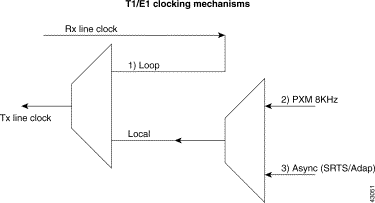
The CESM card provides the choice of a physical interface Tx clock from one of the following sources, as illustrated in Figure 1-1:
1. Loop clocking derived from Rx Line Clock.
2. MGX local switch clock derived on the PXM (Synchronous).
3. SRTS and Adaptive based clock (for T1/E1 unstructured asynchronous mode only).
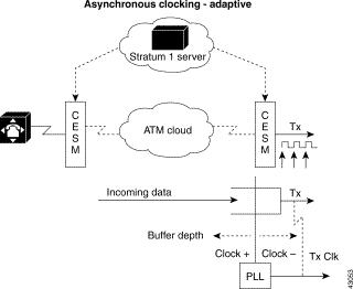
Synchronous Residual Time Stamp (SRTS) clocking requires a Primary Reference Source (PRS) and network clock synchronization services. This mode allows user equipment at the edges of an ATM network to use a clocking signal that is different (and completely independent) from the clocking signal being used in the ATM network. However, SRTS clocking can only be used for unstructured (clear channel) CES services.
For example, as illustrated in Figure 1-2, user equipment at the edges of the network can be driven by clock B, while the devices within the ATM network are being driven by clock A. The user-end device introduces traffic into the ATM network according to clock B. The CESM segments the CBR bit stream into ATM cells; it measures the difference between user clock B, which drives it, and network clock A. This delta value is incorporated into every eighth cell. As the destination CESM receives the cells, the card not only reassembles the ATM cells into the original CBR bit stream, but also reconciles the user clock B timing signal from the delta value. Thus, during SRTS clocking, CBR traffic is synchronized between the ingress side of the CES circuit and the egress side of the circuit according to user clock signal B, while the ATM network continues to function according to clock A.

Adaptive clocking requires neither the network clock synchronization services nor a global PRS for effective handling of CBR traffic. Rather than using a clocking signal to convey CBR traffic through an ATM network, adaptive clocking infers appropriate timing for data transport by calculating an average data rate for the CBR traffic. However, as in the case with SRTS clocking, adaptive clocking can be used only for unstructured (clear channel) CES services. See Figure 1-3.
For example, if CBR data is arriving at a CES module at a rate of X bits per second, then that rate is used, in effect, to govern the flow of the CBR data through the network. What happens behind the scenes, however, is that the CES module automatically calculates the average data rate. This calculation occurs dynamically as user data traverses the network.
When the CES module senses that its segmentation and reassembly (SAR) buffer is filling up, it increases the rate of the (TX) clock for its output port, thereby draining the buffer at a rate that is consistent with the rate of data arrival.
Similarly, the CES module slows down the transmit clock of its output port if it senses that the buffer is being drained faster than the CBR data is being received. Adaptive clocking attempts to minimize wide excursions in SAR buffer loading, while at the same time providing an effective means of propagating CBR traffic through the network.
Relative to other clocking modes, implementing adaptive clocking is simple and straightforward. It does not require network clock synchronization services, a PRS, or the advance planning typically associated with developing a logical network timing map. However, adaptive clocking does not support structured CES services, and it exhibits relatively high wander characteristics.
The CESM T1/E1 card in structured mode can interprets CAS robbed bit signaling for T1 (ABCD for ESF and AB for SF frames) and CAS for E1 (time slot 16). The ABCD code is user configurable per VC (xcnfchan onhkcd = 0-15; ABCD = 0000 = 0 ABCD = 1111 = 15). By detecting on-hook/off-hook states, AAL1 cell transmission is suppressed for the idle channel; thereby reducing backbone bandwidth consumed. ON/OFF hook detection/suppression can be enabled/disabled per VC and ON/OFF hook states can be forced via SNMP through the NMS.
On the ingress end, the CESM card monitors the signaling bits of the AAL1 cell. Whenever a particular connection goes on-hook and off-hook, the CESM card senses this condition by comparing ABCD bits in the cell with pre programmed idle ABCD code for that channel.
When an on-hook state is detected, keep-alive cells are sent once every second to the far-end CESM. This prevents the far end from reporting an under-run trap during idle suppression, since no cells are transmitted. When the time slot switches to off-hook mode, the CESM stops sending the keep-alive cells.
If you configure an individual port for structured data transfer, the 8-port CESM supports:
If you configure an individual port for unstructured data transfer, the 8-port CESM supports:
For each connection, you can configure a tolerable variation in the cell arrival time (CDVT) according to the expected reliability of the route. The CDVT applies to the receive buffer. After an underrun, the receiver places the contents of the first cell to arrive in a receive buffer then plays it out at least one CDVT value later. For each VC, the maximum cell delay and CDVT (or jitter) are
The AX-CESM-8T1 and AX-CESM-8E1 can have 1:N redundancy support but with some variations between the T1 and E1 modes of operation. The type of redundancy and the type of back card are interdependent. In general:
Back card requirements for the MGX-SRM-3T3 and service modules vary, as follows:
The CESM card provides error and alarm management at the card, line, and connection levels. For more information, see "CESM Card Management."
![]()
![]()
![]()
![]()
![]()
![]()
![]()
![]()
Posted: Fri Oct 18 11:15:57 PDT 2002
All contents are Copyright © 1992--2002 Cisco Systems, Inc. All rights reserved.
Important Notices and Privacy Statement.